Chapter Twelve: A cheap gear swap, and it helped too
Riding season is finally close to getting seriously underway here and I'm still waiting on Allan to send the new items to test. I've stated before that I need less top end and more climbing assistance so I was thinking. It's a rainy Saturday, so outside chores are on hold. All the inside stuff is caught up so why not do an experiment on the Blast with the motor gearing. My thought was that a lower assist gearing might get the motor more in it's sweet spot and help pull the hills. How to go about it? Whatever has to be reverseable should my logic be off and I put myself on a $40 budget.
The design constraints are that the 44t drive sprocket is the largest that will fit in the current location due to derailer clearance issues and the motor mount will only go so far outboard before hitting the inner chain ring. Hmm, I knew I needed to get a larger drive ring and or a smaller drive sprocket on. The current gear ratio is about 3.1 to 1 and I wanted to get it closer to 4 to 1, this after the motor gear reduction. To get near 4 to 1 I would need around a 52t ring (common size so it would be cheap and easy to procure a used one for the test) to go along with the 14t freewheel on the motor. This would get me about 3.7 to 1 and if it worked a 13t freewheel would net the magic 4 to 1.
With two Jacksons in hand off I went to the used bike parts store. Rumaging through the chain ring bin I found a decent 52t Stronglite sprocket $5.00 and some change, so far so good. Then a quick stop at the hardware store to get some allen head cap screws, nuts and a hand full of washers for use as spacers to get the ring out far enough to clear the derailer, $8.00 and some change. well within budget. Then home for the installation which started by removing the right crank and ring assembly.
Step one was to disassemble the assembly then center the new ring and match drill it, no problem. Two reattach the motor drive ring and crank then space the new chain ring with chain to clear the derailer. A little trial and error and that too was completed in short order. I then reassembled the entire crank assembly and reinstalled it. Now for the fun part adjusting the motor mount to align the two motor drive sprockets.
To start I moved the mount out as far as I could and still clear the innermost pedal ring. Then I ran it through the gears to double check the clearances. This is a place where those Esge stands pay for themselves, you can run the drive train without a bike work stand as the rear wheel is elevated when the stand is down. Problem was one of the cap screws holding the motor to mount interfered with the chain when shifting to or from the lowest gear, tossing the chain each try. Solution countersink the hole and use a tapered head screw to hold the motor. This of course required removing the crank assembly again to get room for the screw swap. With the mount all the way out the sprockets were still not in alignment so I got out my poor mans mill (round bastard file) and custom made a spacer from a washer that would fit between the keyed motor shaft stop and the freewheel. Rounding third and heading for home I thought, not.
The final step was to install the chain and adjust the mount to take up the slack. Problem....the mount when adjusted to it's max in either direction left me about a half link from an acceptable tightness. What to do? Half links are easy to come by for single speed chains and the like but I had to use a narrow 8 speed chain for clearance reasons. Time for some research, low and behold KMC makes a 3/32 half link around $4.00 or so.
None locally so time to order. OUCH those new USPS rates are brutal! $8.00 to get a $4.00 part delivered! I went ahead and pulled the trigger with an order. $28.00 into the project now so within budget but if I decide to go to a 13t freewheel and the special tool to install I'll be over by $10.00 or so.
There sat the Blast, a block from heaven with a droopy motor drive chain. I just couldn't take the suspense once the clouds cleared for a brief instance. So I mounted up and tried her out knowing that I would be throwing the drive chain if i didn't really nurse it. WOW the difference in pulling power is substantial, I think I'm on to something. Thinking that a 13t freewheel will net me about 15mph or so max with assist just might prove a fair trade for better pulling. As I read somewhere,when I want speed I have plenty of hills to go down.
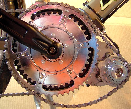
What a stack of chain rings, 5 on the crank. Looks kind of Rube Goldberg. You can see the stock elationebike sprocket through the new 52t job. It's amazing just how quickly rings grow in diameter when you add teeth. I can still use stock elation gearing should I ever go to Kansas and want more top end by quickly swapping out the chain for a shorter one and running the smaller wheel. Of course adjusting the motor mount would be in order but the big wheel can remain installed as I made sure the clearance would allow that. I'll clean it all up and install the half link upon arrival and update this chapter with performance impressions.
Until next time........
- Sturdly's blog
- Log in or register to post comments

Who's online
There are currently 0 users online.
Who's new
- Skyhawk 57
- wild4
- justinsmith07
- Juli76
- xovacharging
Support V is for Voltage

Comments
Re: Chapter Twelve: A cheap gear swap, and it helped too
Sturdly,
Nice work! And I could use some tips no keeping to the budget like that ... :D
I'm anxious to hear how it goes when you get that half link. I bet it helps quite a bit, on your test run you probably were holding back a bit on the throttle, so when the chain is right I bet you see some great results.
Good job, thanks for keeping us up-to-date on your
work! Let us know how it goes ... ;)
Dave
MB-1-E
Electric - Bridgestone MB-1 Mountain Bike
Icon Photo of lighning striking Eiffel Tower Jun 3, 1902, taken by MG Loppe'
Dave B
MB-1-E
<a href="http://visforvoltage.org/book-page/996-mountain-bike-conversion-24v-3-4h... - Bridgestone MB-1 Mountain Bike</a>
Re: Chapter Twelve: A cheap gear swap, and it helped too
Great work. I had no idea you would have to gear that low.
The half link will have to come out when you get the 13 tooth won't it?
Chas S.
My Bicycle Pages
Re: Chapter Twelve: A cheap gear swap, and it helped too
With the 13t I'm pretty sure it will. I'm not sure I will install the 13t, want to try it this way first as I to am surprised at how low the gearing needed to be to get a response I could feel.
Re: Chapter Twelve: A cheap gear swap, and it helped too
I've been doing a lot of thinking about the ratios on this but really I get a little lost when converting the step after power application to the crank. i am not so sure that my formula is correct as you loose a bunch of reduction from the front chain ring to the rear sprocket. Compound that with the multiple ratios available.
My simple mind says that to calculate wheel RPM A (reduction at motor) + B (reduction from motor sprocket to crank) - C (increase of gear ratio from crank chain ring to rear sprocket) = wheel RPM.
In this case motor rpm a shaft after reduction is say 320. (A) =320 + 3.7 to 1 or 320/3.7 =reduction to 86 (B) - 1 to 2.9 at 38t front chain ring on the 13t sprocket 2.9x86 (C) = 249 RPM rear wheel. Does that sound right to you Chas?
I know how to figure it going direct to the wheel or with multiple reductions but add the increase by multiple ratios and I loose it.
Re: Chapter Twelve: A cheap gear swap, and it helped too
This information comes from How Stuff Works. They explain it better than I do.
Understanding the Concept of Gear Ratio
Understanding the concept of the gear ratio is easy if you understand the concept of the circumference of a circle. Keep in mind that the circumference of a circle is equal to the diameter of the circle multiplied by Pi (Pi is equal to 3.14159...). Therefore, if you have a circle or a gear with a diameter of 1 inch, the circumference of that circle is 3.14159 inches.
The following figure shows how the circumference of a circle with a diameter of 1.27 inches is equal to a linear distance of 4 inches:
Let's say that you have another circle whose diameter is 0.635 inches (1.27 inches / 2), and you roll it in the same way as in this figure. You'll find that, because its diameter is half of the circle's in the figure, it has to complete two full rotations to cover the same 4-inch line. This explains why two gears, one half as big as the other, have a gear ratio of 2:1. The smaller gear has to spin twice to cover the same distance covered when the larger gear spins once.
Most gears that you see in real life have teeth. The teeth have three advantages:
* They prevent slippage between the gears. Therefore, axles connected by gears are always synchronized exactly with one another.
* They make it possible to determine exact gear ratios. You just count the number of teeth in the two gears and divide. So if one gear has 60 teeth and another has 20, the gear ratio when these two gears are connected together is 3:1.
* They make it so that slight imperfections in the actual diameter and circumference of two gears don't matter. The gear ratio is controlled by the number of teeth even if the diameters are a bit off.
READ MORE >>>
Chas S.
My Bicycle Pages