
In Using an AVCON style public charger ... I briefly discussed the charger setup on my car. I'm redoing some of it today with an eye to monitoring inputs to the charger during charging, so it's a chance to go over what I did.
The charger is an Elcon PFC3000 set up to handle a 144 volt (45 cell) Thundersky LiFePO4 pack. The charger can take either 120 volt or 240 volt input. Further the BMS requires a 12 volt power supply that's separate from the on-board 12v supply coming from the DC-DC converter.
The separate 12v power supply is coming from a small power brick adapter we found at the local surplus electronics store (http://Halted.com) that itself takes either 120v or 240v input.
Both the charger and the 12v power supply get plugged in to this junction box I built myself:-
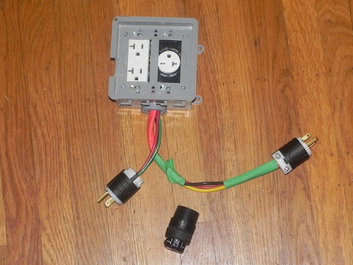
The two pigtail's interface with either 120v or 240v - one of these cords has a NEMA 5-20 (regular 120v) plug, the other has a NEMA 6-20 (240v) plug. Internally both the 120v and 240v sockets are wired together making either 120v or 240v present at the sockets depending on which power source the junction box is plugged into.
That extra thing in the picture is a socket you'd normally attach to the end of a cord. The purpose is to cover the spades on the non-active plug. Because everything is wired together it means the non-active plug will have electricity in them, so for the plug to remain safe it must be covered. Using a socket like this is a convenient way to cover the spades of the non-active plug.
Here's how it looks while in operation:-
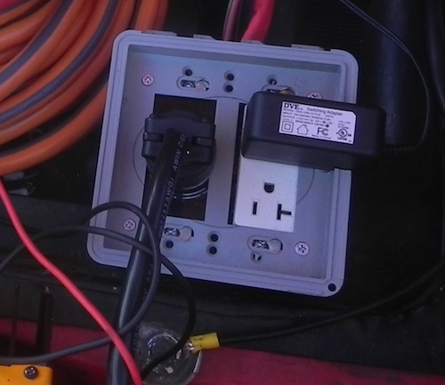
The round plug at the left is from the charger - it has a 6-20 plug on the end of the cord. On the right is the little power plug 12v power supply.
Here's the first step of the redesign:-
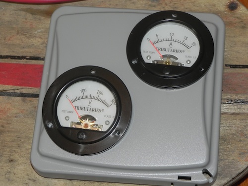
I got these panel meters for $10 apiece from "Skycraft Parts and Surplus". One handles AC up to 300 volts, the other handles AC up to 20 amps. I got a third panel meter that handles DC up to 25 amps.
The idea (I still have to go buy the parts) is to buy two more of these junction boxes. On the AC input side of the charger I'll end up with two junction boxes, one having these two panel meters, the other being the sockets box we see pictured here. On the DC output side there'll be one junction box, with the DC amps panel meter in the box.
The reason to do all this is - to monitor voltages/amps, to better understand what the charger is doing, and to have basic confirmation whenever I'm plugging in the charger that the charger is actually kicking in. So far I've used both AC and DC clamp-on meters and it's a bit of hassle (just a bit) to set that up. I want the confirmation to be there all the time .. e.g. I want to just plug the car in to recharge, and to walk away, and it's best to have confirmation that charging actually started before walking away. e.g. At the end of charging it would be nice to easily see the charging rate has dropped to, say, 1A so I know that it's really at the end of the charge cycle. e.g. if I were talking to someone in public about charging the car, it would be nice to just show them the metering.
I also suspect it'll simplify the wiring inside that junction box - because the existing junction box has way too many wires inside it.

