Voltage drops on a good (NiMH) battery
Now that a voltage readout is available on the Vectrix display, it is worthwhile knowing what other useful information this provides us with.
Because the battery has internal resistance, the volt drop/reduction which occurs when using power actually gives a good indication of the state of the battery.
If the battery is well charged, then the volt drop should be in accordance with the following table:-
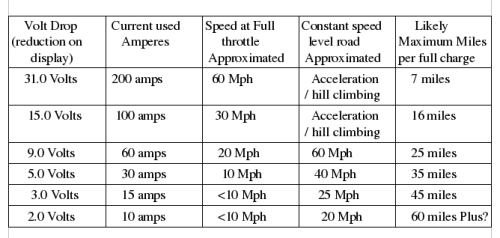
Volt drops well in excess of the above may be an indication of one or more failing cells ( which may be going into reverse voltage).
Volt drops of 5% or 10% greater than above would be expected as the battery ages.
On the subject of Voltage drops.
The internal resistance of the individual cells is a reliable guide as to the condition of the cells. Internal resistance can be measured quite easily with relatively simple tools.
The cell resistance is quoted by 'Gold Peak' as being less than 1.2 milliohms per cell or alternatively 0.0012 Ohms per cell. To measure the internal resistance all that is required is a digital meter having four digit (a 1 and three 0's - sometimes known as a three and a half digit readout) readout and a scale of 2.000 volts. And a suitable load resistor such as a 12 volt 55 watt motor car headlight bulb.
Take a block of (say) ten cells. Measure the voltage of each cell using the 2.000 volt scale of the meter. Connect the 'load' (the car headlight bulb) and again measure the voltage of each cell. Subtract the second voltage from the first (for each cell). Measure the current draw by the load.
Now divide the voltage (the one obtained by subtracting the second reading from the first, two steps ago) The resulting decimal figure is the resistance of the cell.
I have been using this method and have had no trouble picking out the good from the bad cells. Good cells will all give similar results. Bad cells tend to show up very obviously.
If the internal resistance test is passed then complete the job by doing a capacity test. Drain the battery first, that car headlight bulb works well here too. Don't let any cells go into reverse voltage however. Then charge the battery fully using a maximum voltage of 1.45 Volts per cell ( an eight cell block = 11.6 volts and a nine cell block = 13.5 volts).
Finally discharge the battery. Measure the discharge current and note the time taken for the voltage to drop to 1.0 volt per cell (8.0 volts for the eight cell block and 9.0 volts for the nine cell block.
The voltmeter which I am using cost all of £6-00p (english money) and is readily available from electrical stores.
Incidentally, The 'bottom balancing resistors' have worked well. in a test block of eight cells and through numerous charge discharge cycles, the cell voltages have never varied (one to another) by more than 0.01volts.
For those who have forgotten, I fitted a 39 ohm resistor across every cell in the battery with the object of balancing the state of charge at the level of 'empty'. This was my alternative to the constant overcharging of the battery done by the Vectrix charging regime in order to keep the cells 'balanced'.
The Laird.
(Doing it on the cheap once again) and telling it like it is.


Awesome information thanks
Sorry Folks,
I must be getting old or stupid. The paragraph (in the initial post) shown below is missing some information.
Old Paragraph reads:-
Now divide the voltage (the one obtained by subtracting the second reading from the first, two steps ago) The resulting decimal figure is the resistance of the cell.
It should have said:-
Now divide the voltage (the one obtained by subtracting the second reading from the first, two steps ago) By the current drawn by the 'load' (the car headlight bulb). The resulting decimal figure is the resistance of the cell.
Hopefully the article now makes more sense.
The Laird.
(Doing his best to get it right this time).
Very interesting.
under 200 A discharge the battery's voltage drops 31v.
A fully charged pack (140v) under a 200A discharge would drop under 110v. To prevent battery damage, the MC 1017's lower limit of 114v will never allow 200A dicharges.
The original NIMH 30 Ah battery is too small for such powerful engine. The MC should be limited to 4-5C, 120A.
Hi The Laird,
Just had a look at the table and noticed the current under full throttle accleration was a little off, at least compared to what I'm measuring
My nimh bike used to peak at 220A @ 40mph, falling off to 190A @ 60mph
at 30mph, I was seeing 150A
at 0mph, full throttle would pull 30A
Even these values would be a little rubbery, it probably varies a bit between bikes
Matt
Daily Ride:
2007 Vectrix, modified with 42 x Thundersky 60Ah in July 2010. Done 194'000km
Thats actually only true for a damaged battery.
My nimh battery used to hold 117v @ 200A
There was no difference in acceleration between new and old firmware, as the low voltage limit wasn't being reached on either
I never used to use more than half bars, and the charge was always "fresh" (ride immediately after charging)
Matt
Daily Ride:
2007 Vectrix, modified with 42 x Thundersky 60Ah in July 2010. Done 194'000km
Hi folks,
The table was generated a to give a general impression of the effects of current drawn and the resulting voltage drop.
I used data collected from my own bike some time ago when testing full throttle riding from a standing start.
The data was taken from the resulting data downloads.
I have extrapolated from that data to fill in the many blanks and also calculated the voltage drops from the quoted internal resistance of the batteries.
Whilst you are right, Matt, the general impression is still valid. Of course the volt drop will vary with battery state of charge, actual cell resistances and the effects of any damaged cells.
What is useful is the principle that poor cells (high internal resistance / low capacity etc) will produce a larger than expected volt drop when drawing current and this can now be seen clearly on the 'battery voltage readout' incorporated on the latest modified software.
If any or all of this bores the backside off you then perhaps it is just some more of the Laird's scribblings to be ignored?
I do feel that it is all useful information in helping to keep track of the state of the Vectrix batteries.
The Laird,
(Just trying to be helpful).
It looks like the IR calculation can be used with the values that are reported on the CAN bus.
Below are IR calculations using the data from here: http://visforvoltage.org/book/ev-collaborative-hand-books/6916#comment-40025
The voltages and currents were reported during a full-throttle acceleration from zero to 102km/h.
For 1km/h vs 12km/h:
131V - 126V = 5V
58A - 9A = 49A
5A/49V = 0.10204ohm
0.10204ohm / 102 cells = 0.00100ohm / cell
For 20km/h vs 76km/h:
125V - 108V = 17V
218A - 79A = 139A
17V / 139A = = 0.12230ohm
0.12230ohm / 102 cells = = 0.00119ohm / cell
The IR values of 1.0mohm to 1.2mohm are very similar to those that I measured and calculated on the bench, using much lower currents (11A vs 1A).
I think this means that my battery was performing at 100% of specified power delivery when SOC was sufficient.
But the battery tested had several cells with reduced capacity (~25-30% reduction compared to the best cells in the pack), and the IR calculations alone were insufficient to differentiate cells with reduced capacity or increased self-discharge from even the best cells in that pack. The only elevated IR results were found when measuring almost empty cells (after discharge to 1.1V @ 20A). A good cell had 3mohm IR under those conditions, but a capacity reduced cell had double that (6mohm). See https://www.endless-sphere.com/forums/viewtopic.php?f=14&t=6277&start=30#p116761
What do I think it means?
I think it means that excessive voltage drop under load will only show clearly enough when you have an already very badly damaged battery.
Further to this, it is very difficult to find repeatable conditions under real-world driving conditions, making it hard to take reliable voltage readings.
This information may be used entirely at your own risk.
There is always a way if there is no other way!