Hello,
I am building my own 24v trike. Power will be provided by two 12 volt batteries in series. Because of the logistics of the batteries and motors I was hoping I could attach one 24 volt motor to either end of the batteries with a switch on the positive side of each motor. It seems like it should work but I'm not sure. Does anyone know if this will work?
Here's a link to what I am talking about...
http://i273.photobucket.com/albums/jj211/greengothica1/24seriessetup.jpg
Thanks, JY
12v batteries in series with two motors
Thu, 02/28/2008 - 04:06
#1

12v batteries in series with two motors
Who's online
There are currently 0 users online.
Who's new
- Bengun
- Skyhawk 57
- wild4
- justinsmith07
- Juli76
Support V is for Voltage

Ay! No!
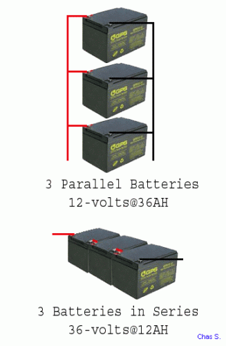
Wiring them up like that will just make the batteries short out across each other!
What you want to do hook up the batteries in series (battery 1 (+) goes to battery 2 (-)) and then hook the motors up in parallel (connect both motor (+) to battery 2 (+) and both motor (-) to battery 1 (-)).
The author of this post isn't responsible for any injury, disability or dismemberment, death, financial loss, illness, addiction, hereditary disease, or any other undesirable consequence or general misfortune resulting from use of the "information" contai
Thanks LinkOfHyrule. That was what I was afraid would happen. With a battery and motor over each rear wheel for even weight distribution I was trying to reduce the amount of wire/cable needed. Batteries in series and parallel motors (individually switched) it is then.
Now I need to figure out how to attach the array of PV cells. Any ideas on where to attach it to the batteries? Do I just splice it into the plus and minus cables at the end of the batteries in series like the motors, as shown in my updated drawing...
http://i273.photobucket.com/albums/jj211/greengothica1/24seriesparallelsetup.jpg
Thanks again,
JY
There's still something not quite right. Study this over & then resubmit your sketch?
Yah, according to your newest sketch, the batts will still be shorting out through each other. Same with the PV cells.
Also, it's not a good idea to just attach PV cells directly to the battery. While it won't to any harm to the cells, the batteries could get overcharged, or even not charge at all. What you need to do is run them through a battery charger. The switching chargers (no transformer; lighter weight) should work on DC.
The author of this post isn't responsible for any injury, disability or dismemberment, death, financial loss, illness, addiction, hereditary disease, or any other undesirable consequence or general misfortune resulting from use of the "information" contai
I don't see any shorts. This is the way I have been connecting batteries for... well lets just say a long time.
Here is my old diagram, looks the same to me.
Frxdy, looks to me like it is right.
To connect batteries and PVs together you need a device called a "Charge Controller".

Grandpa Chas S.
I've never seen that sort of thing. So it's basically a battery charger that runs directly off of PVs? Neat.
And Frxdy's drawing is fine. It's JY's that's knackered.
The author of this post isn't responsible for any injury, disability or dismemberment, death, financial loss, illness, addiction, hereditary disease, or any other undesirable consequence or general misfortune resulting from use of the "information" contai
Sorry I C
I didn't look at that drawing on photo bucket.
He has the batteries shorted big time and the motors will not run. The only thing that will happen is the wires will melt. If he were to turn 1 battery around then he would be putting everything in parallel when both switches are on so it would run 2 24-volt motors on 12-volts. Not a good idea, it will just suck the batteries dry in short order.
Grandpa Chas S.
Yeah, same with the PV cells.
Motors are fine, but you don't need that many switches. One on the + side of the batteries and 1 on one of the solar panel poles will be fine.
The author of this post isn't responsible for any injury, disability or dismemberment, death, financial loss, illness, addiction, hereditary disease, or any other undesirable consequence or general misfortune resulting from use of the "information" contai
I was trying to edit my last post as it was in error, check it now. LOL
He needs to line up all the +'s with the +'s and the - with the - and all would be OK with the batteries and PVs.
Grandpa Chas S.
Wow! Thanks for all the help. Frxdy, Chas and Link, I think I have it correctly now.
http://i273.photobucket.com/albums/jj211/greengothica1/24seriesparallelschargeretup3.jpg
Too many switches?
I wanted each motor switched so I can run on one or both motors depending upon load, hills, more speed, less speed, etc.
Thinking aloud...
Perhaps two small motors will run more effeciently than one larger motor carrying the whole load by itself. Effectively spreading the load over two motors making each motor work half as hard and extending its life. Perhaps not?
With a potentiometer...
One motor @ 22 amps VS two motors @ 11 amps each
Seems like it will even out to the same amp draw. But at full amp draw (44 amps) of course the speed would increase but the precious batteries would drain faster.
I wasn't planning to run a potentiometer, just 50 amp on/off switches. Wouldn't one motor theoretically mean half the top speed at half the amp draw, 22 amps. When I switch on the second motor wouldn't the speed increase significantly, as well as the amp draw double, 44 amps without the potentiometer?
Unless of course the first motor's rpm's were already maxed out and I'm going DOWN a steep hill.
Since I am talking motors...
For my first prototype test motors, I am going to run two 24 volt, 350 watt, 22 amp, 2600 rpm scooter motors. One on each rear wheel. My goal is to travel a looooong distance at a reasonable speed. When I want more speed just switch on the second motor. They both together may not move the estimated 500 pound with batteries trike, I wont know til I try them.
Thanks for the charge controller link, Link (no pardon intended). Once I figure out what cells I will be running I will definately get one of those. I am along ways from PV cells however. I just took my first test drive yesterday under peddle power. For the front wheel and steering I used a Unicycle and a steering arm attached where the seat goes (reverse Tillar). The 1 mile test went well but I was worn out after the mile of peddling a unicycle while dragging 300 lbs (me and frame, chassis. No batts or motors) behind it. No brakes yet, but I didn't crash and my all aluminum square tube, 90 degree right triangle-shaped frame didn't break. I modeled its shape after a 70's CitiCar I used to have, without the body. The Unicycle wheel steered fine but I had to take my feet off of the peddles to coast or when I went too fast (only 5 mph probably). I dont plan on having my feet on the peddles at all except maybe to help it get started from a standstill. The peddles are just to keep within the electric bike laws. As long as it has working peddles and goes <20 mph its a bicycle (trike in this case), and no registration, license, insurance, etc are necessary.
more to come...
Thanks you guys,
JY
In theory, two motors would be equal to one bigger motor. In reality, it seems that one bigger one is better. Not by much, though. Don't know why.
Potentiometers = terribly inefficient. They were ditched long ago (like 100 years ago) in place of PWM (pulse width modulation). This is akin to flipping a light switch on and off really fast. If you want speed control, use a proper scooter controller. 24V ones are pretty cheap. Less than $30 including shipping.
"I wasn't planning to run a potentiometer, just 50 amp on/off switches. Wouldn't one motor theoretically mean half the top speed at half the amp draw, 22 amps. When I switch on the second motor wouldn't the speed increase significantly, as well as the amp draw double, 44 amps without the potentiometer?
Unless of course the first motor's rpm's were already maxed out and I'm going DOWN a steep hill."
Your current draw is only dependant on the torque needed to move the bike. Say you have one motor going at 2600rpm and drawing 22 amps. If you flip another one on (that's in parallel), then both motors will be going at 2600rpm, but only be drawing 11 amps each.
If you go down a steep hill and the motors are already maxed out, they'll generate enough back EMF to start charging the batteries, actually.
And Chas gave you that link ;).
The author of this post isn't responsible for any injury, disability or dismemberment, death, financial loss, illness, addiction, hereditary disease, or any other undesirable consequence or general misfortune resulting from use of the "information" contai
Hi Link,
One big motor better than two smaller motors?
Friction, weight, resistance due to the extra wire?
Now I'm confused again...
Amps dont necessarily increase with rpms, but the amps increase with load? I could have 800 rpms and have 22+ amps of load due to weight/drag? I assume that over a short period of time the motor would burn up in this scenario. And conversally, I could have 2600 rpms and draw only 10 amps going down hill?
Switching on the second motor is supposed to be my speed control. A two-speed speed control? Twice the power suddenly to move the same load should theoretically increase the speed. I really doubt that on level ground one little 350 watt motor will be able to spin to 2600 rpms trying to push over 500 pounds down the road. So, if I am travelling at say 10 mph on one motor struggling at 22 amps of load and then flip on the second motor the torque should increase significantly while spliting the load in half between the two motors. I am hoping that I can use both motors to get moving then switch off one motor and maintain a reasonable speed thanks to Newton's first law of motion or Galileo's law of inertia.
When a motor has a 22 amp rating is that the recommended maximum safe amp operation rating?
My worry is that with one motor switched off the drag that it will cause will be too much. Almost better to switch it on than have it drag. There goes my two-speed speed control theory out the window.
I have been reading a little about PWM's and back EMF. With EMF doesnt the output of the motor (now turned generator) need to be greater than the batteries already have stored? So if the batteries only have 20 volts stored in them but screaming down the hill creates 26 volts at 2600 rpms, with the switch on, the flow will be automatically reversed into the batteries charging them?
Oh, thanks Chas for the charger link.
Thanks Link,
JY
The real problem with using a switch and no controller is the motor will draw max current when the switch is on. The second motor will do the same. If the batteries are capable of putting out 100 amps the motor will draw 100 amps as soon as the switch is turned on. Motors are dumb they have no way to regulate themselves. Look at it this way, a motor is nothing more than a very long piece of wire. If you take 1000 feet of wire, lay it out in a big circle and connected the ends to a battery you would have a short circuit. Lots of amps would flow through the wire until one of 3 things happened.
1. The wire would get hot enough to melt.
2. The battery would get hot enough to explode.
3. The battery would discharge rapidly to 0-volts and be worthless.
The current flow would be the same if you connected a second 1000 foot wire adding nothing to the power equation. In other words a second motor in this configuration would do nothing to help the first motor.
Another item I think you need to know is "Current (amps) equals torque", "Voltage equals RPM". Adding more amps to the motor will not make it turn any faster. This just makes it get to top speed quicker. Adding voltage will make the motor turn faster or give you more RPM.
If you take a 24-volt motor that runs at 2600 RPM and add another 12-volts to it so it is now running at 36-voltage the RPM of the motor will increase to something around 3800 RPM. This is know as over volting the motor, I am sure you have seen that term here on V in other posts.
I have one e-bike which uses a 24-volt motor. I replaced the controller with a 36-volt controller and added another 12-volt battery to my pack. With the 24-volt battery pack and controller @ 26 amps the bike would top out at around 18 MPH, with the 36-volt battery pack and controller also at 26 amps the bike tops out at 23 MPH. I have over 300 miles on the 36-volt conversion and the motor is still running great. If I did not have a controller on this bike the motor would draw over 100 amps and get to 23 MPH very fast, if the motor did not toast in the first 8 seconds, then the motor would let go it's magic smoke and the ride would be over.
Grandpa Chas S.
I can see why it would go faster because you now have 500-watts doing the work that was previously done by 250-watts.
I can also understand why you have more range. Before you were running 1 24-volt pack and now you are running 2 24-volt packs. This just doubled your amp hour (AH) rating. More AH equals more range.
All of this is consistence with the laws of electronics.
Grandpa Chas S.
Ah Ha! Basic Electricity 101. My High School memories are slowly coming back.
I really appreciate all the help guys. I know very little about electric motors.
Very little about IC engines either, but I get lucky with the 9 second 1/4 mile BB Fords I've built for my Stangs over the last 25 years, but thats for another forum.
Reading some of the other posts gets me to thinking about making an EV dragster out of my 42 Willys A-Altered I have sitting around collecting dust just waiting for a drivetrain. All it takes is money.
Link and Chas,
I'm confused again...
Is there a contradiction here or am I misunderstanding what you two are saying?
Link
"Your current draw is only dependant on the torque needed to move the bike...."
Chas
"The real problem with using a switch and no controller is the motor will draw max current when the switch is on..."
Will the motor only draw what it needs to move the bike or will the motor just use all available amps that the batteries can give it once I flip the switch to move the bike AND then the load taper off once the bike is moving?
I've been looking at a few PWMs, they have alot of wires for motor, throttle, battery, brakes. Will I need two controllers and two throttles since I am running two motors? Or do you guys think I should give up on the two independently switched motor idea and just wire them together in parallel so the both come on (and go off) together? Either waysince my motors are 24v/350w/22a can I use one 24v/350w controller or two of them, OR perhaps find a 24v/700w controller?
I designed the rear leaf spring suspension today. Single leaves, coil over shocks. A quick trip to Lowe's tonight to get the right bolts and tomorrow assembly.
Here is a drawing (no pics yet) of The Love Buggy, as my GF calls it. She helped clean and paint the frame royal blue today.

Now if I can figure out how to post a pic in this thread once the tuturial loads?
It looks just like this when it is assembled. The diagonal supports and side skirts are removeable.
Thanks again for all your valuable input and sharing your knowledge with me.
JY
"Will the motor only draw what it needs to move the bike or will the motor just use all available amps that the batteries can give it once I flip the switch to move the bike AND then the load taper off once the bike is moving?"
Yeah, it'll draw a lot of current momentarily to accelerate and then taper off as you approach your top speed. They're relatively small motors, so you might not have a problem unless you are flipping the switches on and off a lot. A controller limits the current to a set value, so you never draw more than what it's programmed for.
"I've been looking at a few PWMs, they have alot of wires for motor, throttle, battery, brakes."
And that's just a basic one. I have one for a skateboard that has connectors for the battery, motor, throttle, brakes, key, two lights, and charger.
"Will I need two controllers and two throttles since I am running two motors? Or do you guys think I should give up on the two independently switched motor idea and just wire them together in parallel so the both come on (and go off) together? Either waysince my motors are 24v/350w/22a can I use one 24v/350w controller or two of them, OR perhaps find a 24v/700w controller?"
No. One suitably sized controller will be fine. If you use a controller, there's really no point to having switches on the motors. Turning one off won't affect the performance much; it will just push the motor harder. A 24V 350W controller will limit the current to around 20A, so you'll need a bigger one to run them in parallel. There aren't that many controllers that are 24V 40A, though, because most systems of over 400W or so run off 36V. Less resistive losses that way.
The author of this post isn't responsible for any injury, disability or dismemberment, death, financial loss, illness, addiction, hereditary disease, or any other undesirable consequence or general misfortune resulting from use of the "information" contai
What LinkOfHyrule said is correct what he did not say is the motor will draw the max amps the batteries can put out. So if your batteries can put ot 100 amps that is what the motors will draw. With a 350-watt motor something will smoke. I would use a PWM controller and the motors in parallel. Most lead acid batteries can deliver well above 100 amps.
Grandpa Chas S.
[/quote]
what he did not say is the motor will draw the max amps the batteries can put out. So if your batteries can put ot 100 amps that is what the motors will draw. With a 350-watt motor something will smoke. [/quote]
I don't believe so.... if the motor is a 350 watt motor, it will draw 350 watts. Think of a light bulb that draws 15 watts. Just because the batteries can put out 100 amps, the bulb will not blow, it will just draw what it's rated for.
Not necessarily. The motors are RATED at 350W continuous, but will draw much more power if suddenly given a power source.
However: The will not draw whatever the batteries can put out for any appreciable amount of time. True, at stall they will draw a significant current, but assuming they are not undersized for the load (or at least geared for plenty of torque), they will only do this for a small amount of time.
I've seen a few cheap (or experimental) scooters (and one go-kart) that simply used a few batteries and an array of relays to switch voltage levels. Obviously, they lacked fine speed control, but they worked, and the motors handled the load fine (even when overvolted).
But, it doesn't really matter if you decide to use a controller. Then it's not so much what the motor can take as it is what the FETs can take.
The author of this post isn't responsible for any injury, disability or dismemberment, death, financial loss, illness, addiction, hereditary disease, or any other undesirable consequence or general misfortune resulting from use of the "information" contai
OK, lets look at some simple electronics.
What is the resistance of a 100 watt light bulb?
(E*E)/P=R
(120*120)/100=144 ohms
OK 144 OHMS of resistance in a 100 watt light bulb.
How much resistance is there in a motor? less then 1 ohm, here is the explination.
When power is first applied to a motor, the armature does not rotate. At that instant the counter-emf (resistance) is zero and the only factor limiting the armature current, is the armature resistance. Usually the armature resistance of a motor is less than one ohm; therefore the current through the armature would be very large when the power is applied. This current can make an excessive voltage drop affecting other equipment in the circuit and even trip overload protective devices. As the motor spins faster the resistance of the motor increases and the current through the motor will decrease.
So if we assume 1 ohm of resistance and use the formula; I=E/R at 24-volts the current draw will be 24-amps but we know the resistance is less then 1 ohm. If the resistance is .5 ohms the current is now 48-amps using 24-volts. If the resistance is .3 ohms the current is now 80-amps using 24-volts. Now you can see how fast the current flow can increase. If we choose .1 ohms at 24-volts which is about as close to the start of the motor as we can get the current flow would be 240 amps assuming the battery could produce that much, get the picture? Remember a motor is nothing but a long piece of wire. If you take a long piece of wire the resistance is very low and the wire will flow loads of current if there is nothing in the circuits to give resistance to the current flow.
Grandpa Chas S.
Simple electronics? Well, after reading that I guess I wont make a switch controlled 240 amp 2000' wire arc welder out of my little motors. Thanks for saving me that money Dr. Grandpa.
I have bought the two new motors, four new sprockets, lots of new #25 chain, new wheels, and one new battery so far And, the trike frame and suspension are almost finished.
So, do I run my two 24 volt/350 watt/22 amp motors and two matched 24 volt controllers powered by two Group 27 Marine deep cycle batteries in series with my 11 tooth drive gears and 55 tooth wheel gears with my 15.5" diameter tires on my trike weighing at least 500 pounds?

Like this...
OR, do I overvolt my little motors with two 36 volt/500 watt/30 amp controllers and add one more 12 volt battery?
OR?
Can you tell be looking at these motors I bought and tell if they are brush type or not? The ad says that they are permanent-magnet motors. Does permanent-magnet motor mean that they are brushless?


Any ideas, suggestions and/or criticism is greatly appreciated. You guys are helping me so much I cant thank you enough.
JY
OK I like to take things one at a time. Makes it simpler.
1. You don't need the switch between the batteries and the charge controller. This connection does not need to be switched. Allow the solar panels to give you all the power they can even when riding. The charge controller will maintain the batteries for you.
2. The motors you have chosen are brushed motors so no problems there.
3. The 2 "SC" (PWM controllers) each have their own throttle. How do you plan to control the motors? One throttle with each hand?
Grandpa Chas S.
Simple's good.
1. I'm a control freak. I dont understand all this stuff yet so the switches let me shut everything down if something goes wrong. Ok, the PV charge controller switch is out. Can I keep the MAIN kill switch just incase I fry something and the motors go wide open.
2. Glad to hear that they are brush type motors. Makes PWM controllers cheaper and easier to find. Thank you.
3. Not sure yet. But I think that answers one of my questions. One (48 volt) throttle cant be spliced to control two 24 volt PWM speed controllers? Perhaps lining them up side by side since they are so small with a removeable bracket across both thumb levers so they both move together when I want them to? I have really big thumbs (and feet). Grow another thumb on one hand? :) Use two hands? I like the idea of contolling them individually still. I cant let go of the idea that only using a 1000' wire "will" save battery power over a 2000' wire. I believe you, and I'm trying to let that one go, but its hard. I use dual carbs on my race engine, It should be the same, It should.
It should. It should. It should. Sorry, I digressed.
Eagerly awaiting 4. & 5. especially about overvolting. Seems like Nitrous Oxide for EVs.
I wont mention the sail that I am fabricating for the trike.... yet.
Thanks Chas
short answer - NO!
Why? The throttle is the same for most controllers. It is either a Hall effect sensor or a 5K ohm pot (potentiometer/ variable resistor). This is a simple device which normally uses 3 wires to tell the controller how much power to send to the motor. Throttles normally have 3 wires, one wire is normally +5-volts dc, The other is 0-volts dc, and the last wire is the control wire and varies between 0 and 5 volts dc. This of course is stated in general terms and actual voltages may vary some for controller to controller but by less than 1 volt.
That is a mechanical solution that might work but not very elegant. You could take the ground wires and the control wires from each controller and wire them to 1 throttle. Wire the +5 volt wire from only 1 controller leaving the other controller's +5 wire not connected. The only other thing you need to do to make this work correctly is to place a wire from the negative side of one battery pack to the negative side of the other battery pack so ground is the same for both controllers.
OK we go back to simple electronics. When you calculate 2 resistors in parallel use the following formula . So 1000 feet of wire has a resistance of x, for ease of calculations we will say x=1000. You do not add the 2 motors together, that would be series. The configuration you are using is parallel. So if x = 1000 then
1000 * 1000= 1000000
1000 + 1000 = 2000
1000000 / 2000 = 500
So as you can see the total resistance does not add but in fact in this case is cut in half. Back to the other formulas.
I = E / R so if we look at the current flow for 1000 ohms at 24 volts we get 24/1000=.024 amps
I = E / R so if we look at the current flow for 500 ohms at 24 volts we get 24/500=.048 amps
This shows, as the resistance decreases the current increases proportionately. Yes dual carbs uses twice the fuel and so do dual motors. You just have to use the correct formula to see it.
Grandpa Chas S. (A.K.A Mr. Wizard)
Two thumb throttles side by side. They work on my stand up scooter. I think it might get uncomfortable after a while on a bike. I added a rubber stubby on the outside one to make them line up properly.
Free Willey...
Ride on Shamo...
Sorry I don't know what came over me. I think this will work but you better have a really big thumb.
Grandpa Chas S.
Ay, that's a monster of a throttle! LOL, what's with the orca "hood ornament"?
IMO, tying the throttle wires together would be the best way to go.
The author of this post isn't responsible for any injury, disability or dismemberment, death, financial loss, illness, addiction, hereditary disease, or any other undesirable consequence or general misfortune resulting from use of the "information" contai
This should be self explanatory but if you have questions please ask. Remember there are no dumb questions only dumb answers. I thought you might like this because it gives you the ability to disable one motor and only use it when you need the extra boost. Of course the easier way is just to turn the key switch off for one controller which also disables one motor.
Please note - The diagram shows the green wire switched to the red wire. This is correct for some controllers but not all. If this does not work then place the switch between the green wire to the black wire and the controller will be disabled. The easy way to find which way to wire this setup is to take a voltage reading across the green and black wires when the throttle is in the off position. If the voltage is near +5 - vdc then place the switch on the red and green wires. If the voltage is 0 - vdc then place the switch on the black and green wires. (Wire colors may vary but the principal is the same)
Grandpa Chas S.
Fantastic! Thank you! That's what I was hoping could be done. But, I had no idea how to do it. I have a vivid imagination, just no knowledge. I would have fried 4 or 5 or 10 motors, throttles and controllers trying to figure out the correct wiring to do this. I am even buying the "elegant" 4 wire throttle so I have pretty little LED lights. Even though I am an all go, no show kinda guy. I am past the point and transcened trying to attract a mate with fluffy Peacock feathers.
Frxdy, only one thumb required. Upgrade?
I may be dumb, but I am not stupid... perception is our own reality.
Ok gentlemen, you are missing the bigger picture here...
The motion of air, particularly when it interacts with a moving object. Understanding the motion of air (often called a flow field) around an object enables the calculation of forces and moments acting on the object. Typical properties calculated for a flow field include velocity, pressure, density and temperature as a function of position and time. In this case, we are talking about aerodynamics through mathematical analysis and empirical approximation called subsonic since all the speeds attained by Frxdy's stand-up scooter are most likely going to be less than the speed of sound. Frxdy's ingenuious design not only includes Shamu The Killer Whale's external aerodynamics to increase the flow around solid objects of various shapes, in this case, Frxdy. Evaluating the lift and drag on an Shamu's positioning, Shamu's angle of lift, or in this case, down pressure assures continued traction at high speeds. Also, the shock waves that form in front of the nose of Shamu are minimal as the flow of air passes by it futher increasing the miles per amp ratio (F=N*W/snot). The influence of potential air viscosities in the flow involve only negligible viscous effects on the solution, so in this case viscosity can be considered to be nonexistent.
Futhermore, not only does the aerodynamic Shamu reduce drag as it helps Frxdy to cut through the wind at high speeds like a bullet, that cute little basket defuses the air flow below Shamu creating a phenomena called vortex futher increasing the difference in pressure between the upper and lower surface of Shamu's side fins. This is revealed by colored smoke in the picture below, taken by an high speed camera with a partial zoom lense of Frxdy zipping down the road on his scooter.

Well. at least it sounded intelligent.
If Frxdy ducks down, it will help too.
Okay Chas, you have convinced me. So much so that I am removing one carb and adding a second starter on my race car tomorrow.
Thanks guys.
JY
Pages