
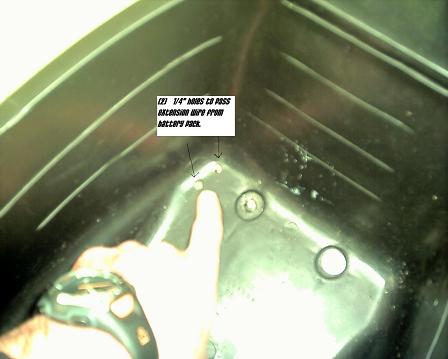
Here is how I took my X-treme xb 600 from 48v and 21 mph to 60v and 30 mph. First, you will need to remove the battery pack and seat. Also, take the lid off of the battery pack and make sure all the connection screws are tight(some of mine were loose). Next, drill (2) 1/4" holes in the corner of the seat pan in the left front corner. See Below...
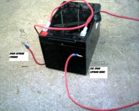
Now, cut the black wire coming from the last battery's negative post and attach a length of 12 ga. or better wire to each black wire long enough to reach up to the storage area under the seat. The wire coming from the 4th battery's negative will go to the 5th battery's positive post. The other wire will go from the 5th battery's negative post to the plug that the black wire we just cut went to. Then route the 2 new wires through the hole in the battery box beside the plug. See Below....
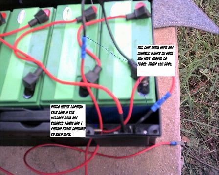
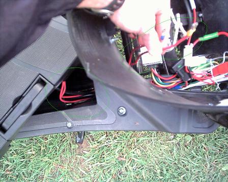
Now would be a good time to put a piece of black tape on the wire that will go from the 5th battery's negative wire to the plug. This will save confusion when wiring everything together later. Or you could use black wire on the negative which I didn't think of until now. LOL! When you have done these steps put your battery box lid back on and rout your wires along side the battery pack plug along the frame and pull them up to the seat area in front of the controller. See Below....
Now install your seat pushing the wires through the 2 holes you drilled in the start of this project.
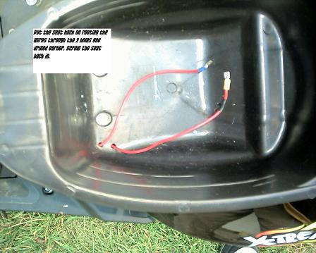
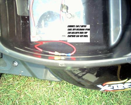
Now, put a female spade connector on one wire and a male spade connector on the other wire so you can plug these 2 wires together to charge the 48v pack with your stock charger. Now it is time to wire the 5th battery. Use any length of wire with a female spade connector on one end(If your battery has this kind of post). You will need one for the negative terminal and one for the positive. Now, remember that piece of tape you put on your negative wire coming from the battery pack plug? Good. If you put a female terminal on the end of it, you will need to put a male spade connector on the end of the wire that plugs onto the 5th battery's negative terminal. Also, I suggest using black tape on the 5th battery's negative wire or black wire so you know which wire plugs onto which post, because you will have to remove them from the terminals to charge the 5th battery with a standard 12v battery charger. See Below....
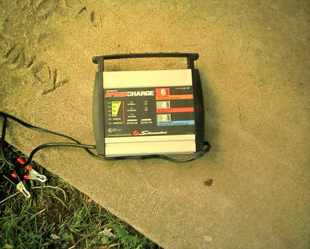
Here is the $28 charger I bought at the local Wal- Mart to charge my 5th battery...
This is how you will connect the 2 wires coming up through the seat for charging the 48v pack with the stock charger...
Now, the fun begins.
**IMPORTANT**
If you used a Female spade connector on the positive wire coming from the 48v pack(the wire you didn't put black tape on) then you will need to put a Male spade connector on the wire coming from the 5th battery's positive terminal. Likewise, you will put a female spade connector on the 5th battery's negative wire. This way, you should be able to connect the 2 battery pack wires together AND connect the positive wire to the 5th battery's positive, and the negative pack wire to the 5th battery's negative when you are ready to ride in 60v. Now, let's wire it up for 60v.
With all of your spade connectors in place, connect the positive wire coming from the battery pack(yes, this is actually the wire coming from the 4th battery's negative) to the wire that connects to the 5th battery's positive terminal. Do the same on the negative.(Both wires that had black tape should be hooked together) See Below....
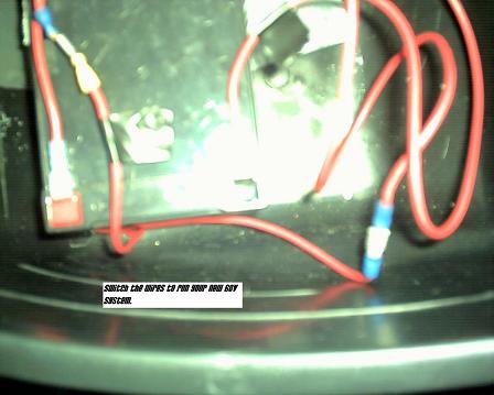
You are now running 60v on your 48v scooter. If you have already done the shunt mod on your controller (E-max Controller Mods - Shunt Resistor Trick) then you are about to have some real 30mph fun!! Actually if you haven't done the shunt mod I would suggest you stop right now, take off your controller, get out your soldering iron and drill, and do it first. As soon as I figure out how to get video off my cell phone and onto my pc I'll put a vid of my speedo as I'm going 30 mph up on youtube and link it here. Till then here's a pic of my latest mod. :)

I hope this thread will be useful for all who own xb 508s, xb 600s, or any other electric scooter. Post questions here and I'll do my best to answer them. Thanks for all the help I've gotten from this forum and I hope this helps someone in return.
-Warren


Here is a link to a video of my speedometer I put on youtube. The video was captured on my cell phone so it's not the best quality, but it's still pretty clear. Check it out.
http://www.youtube.com/watch?v=N2Sr590DSgw
Keep the rubber side down and the shiny side up.
I found a website that sells 72v dc-dc converters for $34.58 including shipping. Can anyone guess what my next mod is? LOL Here is the link :D http://www.power-factor-1st.com/shop/dc-dc-converter/on-board/sd-15.html
Keep the rubber side down and the shiny side up.
Hey, thanks for the great explanation and pics! Just saw AF's post about the new 700 watt lithium e-bike coming from xtreme. I'm thinking I might have to move up to that model when it comes out! But sooner or later I'm going to just have to make the leap and do these mods on the xb600. How simple and boy I know what the difference will feel like...running 30 mph and 25 on hills! Thanks again for all the excellent info!
Gushar
Gus
Zerogas-
Looking at that again...so you're cutting the black wire inside the battery box where it leaves the last battery going to the receptacle (male side I think) built into the box? Instead can you just cut that black wire (and add the lengths) on the "other side" of the plug...the female side that plugs into the battery box receptable? That way you can still completely remove the battery box by unplugging the plug as usual.
Just wondering if I'm understanding this correctly...
Gushar
Gus
Gushar,
I tried wiring the battery in after the plug the first time, but for some reason all that would give me was 12v to the controller and system. I'm not sure why. Wiring directly into the pack works perfect though, and yes it is the black wire going into the receptacle that gets cut. With the spade connectors on the end of the extension wires going up through the seat you can still remove the battery pack. all you have to do is push the spade connectors back through the holes in the seat pan and pull them back through the hole where the plug is that plugs into the pack. These wires are easy to route back through the seat when you need to, by reaching behind the scooter and up to the seat pan. There is plenty of room to work back there. :) Also, check out the 72v controller I ordered from ecrazyman [at] gmail.com . This controller has 100v FETs so it can safely go above 72v even!!! Some people have run them at 84-90v with no problems! http://endless-sphere.com/forums/viewtopic.php?f=2&t=4282&p=63528#p63528 Hope this clarifies things.
Keep the rubber side down and the shiny side up.
By the way,
The controllers can go to 84 or 90v, but I wouldn't try it. These hub motors are rated 24v- 72v so I'd say 72v is maximum for reliability. 72v may even be pushing too much. We'll see....
Keep the rubber side down and the shiny side up.
"Don’t try this at home. We’re what you call 'professionals'."
LOL! ;-)
<table border="0" style="border:1px solid #999999; padding:10px;"><tr><td>
<a href="http://www.BaseStationZero.com">[img]http://visforvoltage.org/files/u419...
[size=1][color=black]www.[/color][color=#337799]BaseStationZero[/color][co
Don't try 72v on the xb 600. The motor didn't like that much voltage at all. It chugged and vibrated badly on takeoff. Top speed wasn't much more anyway, so 60v seems to be best for the 600 watt motor. It takes off fast and 30mph is as good as a 50cc gas scooter, so go 60v and you'll be glad you did. If you need more than 30 mph you'll need a higher watt motor to go with the 72v controller. Also, there is no hookup for the speedometer on the 72v controller, so you'll need another method of measuring speed too. If anyone gets more than 30mph on 72v post here please. Let us know :D
Keep the rubber side down and the shiny side up.
Hmmmm...still makes me curious why that extra bat hookup after the plug doesn't work??? But anyway, I see what you're saying about doing it in the bat box...and just pulling the wires through if you need to take the box out. Pretty easy I'm sure.
Just saw your later post. Can't say I was surprised about the 72v being a bit high for the motor. I'm certainly not as knowledgeable about the volt/amp/motor thing as many here...including yourself I'm sure...but I had a hunch that might be just too much voltage for that motor.
Again though, what you've done with the 60v and shunt mod is most appreciated. At least we reasonably know that works without a hitch...and greatly improves performance!
Gushar
Gus
Yeah, I've been running 60v almost 2 weeks now with no problems at all. I even pick my daughter up at school after work and the scooter carries us, her backpack full of books, and (3) 2 liters of mountain dew with no problem. The 60v mod is awesome and so far I have seen no negative effects to any components on the scooter. It takes off like a rocket and I can even ACCELERATE UP A HILL!!! LOL It makes the scooter sooo much more fun to ride, and it's as fast as a 50cc gas scooter for 1/2 the cost. You can't beat that.
Keep the rubber side down and the shiny side up.
Oops, it's been a week. Sorry, it seems like much longer, LOL. Anyhow, I'll keep everyone posted on how the 60v mod is going and if there are any negative effects of it. So, far it's perfect. Even the dc-dc converter has no problem with 60v input.
Keep the rubber side down and the shiny side up.
Hi all,
Just wanted to drop a line and let everyone know how the 60v mod is working out. I rode my xb 600 to work everyday last week and I'm happy to report that it's working perfectly. Normal top speed is 28mph although I still get to 30 for a bit when it's fresh off the charge. By the time I load it down with 3 2-liters of mountain dew, pick up my daughter and her back pack full of books top speed is 26-27mph, still tons better than 21mph. I'm still looking for a higher watt motor (1500-2000 watt) for the 72v conversion since the 600watt couldn't handle that much voltage. If anyone has one let me know. Overall, I'm extremely happy with the way the 60v mod/shunt mod turned out. I encourage others to do this mod, it makes the scooter so much more fun to ride and I can keep up with the 50cc gas counterparts :) I'm also looking to start an electric car conversion now, so if anyone wants to donate a geo metro or ford escort or something along those lines, drop me a message :D
Keep the rubber side down and the shiny side up.
Glad to hear things are working well. I love the simple step-by-step instructions you provide here for the conversion, and I'm very interested in performing this myself.
A couple of questions (forgive my ignorance here, I'm completely new to the scene):
A) It's a rough trade-off to lose that storage under the seat... is there any other place on the bike to store the extra battery? Perhaps if you dismantle the frame, is there another nook that you can stick it into? Perhaps if you had, say, two smaller batteries instead of one larger battery? Or, is it possible to completely replace the lead-acid batteries in the battery containment bin with a combination of batteries that would give you the 60v you're looking for?
B) Please help me understand what the "shunt" does, and why it's important to perform this mod. I'm afraid I just don't get what it does, and I'm a bit reluctant to go near the controller with a soldering iron unless I have to. Also, if it is such an important hack, can you describe exactly how to do it (including what type of wire, what kind of solder to use for this kind of job, where exactly I'm soldering, etc)? The thread that you link to has several people each with their own opinion...
C)How would you be able to switch between 48v and 60v on the circuit? It would be nice to wire a toggle for "turbo" mode and only switch it on when you need that extra boost, thereby conserving the energy in the fifth battery.
D) I charge my battery by lugging the battery into the house (no power in the shed where I store the bike). Is there a way to wire the bike with the additional battery so that 1) the second battery is easily removable (so I can charge that one inside as well) and 2) to wire the fifth battery's terminals closer to the controller so that the main battery is still removable (i.e. not hard-wired)? If so, please help me understand how...
Regards,
-Mark
[url=http://www.markmilley.com/scooter/]Check out my up-to-date savings and ROI![/url]
Ok,
The shunt mod is what gives you better acceleration and hill climbing. The shunts in the controllers limit the amount of amps the motor can draw. Without amps the motor doesn't draw more "power" on hills. To allow the motor to draw more amps you must modify the resistance of the shunt. This is accomplished by changing the size of the shunt(length and/or thickness or both) The link above will show you what a shunt looks like. In these controllers it is the 2 strips of arched metal near the middle of the pcb board in the controller. There isn't much to solder to around the shunt so you will have to drill (2) 2mm holes as close to each end of the existing shunt as you can and solder the coathanger from the back side. I used a 1.5 inch length of coathanger bent into a U shape and it works great. A longer piece may work better, I don't know. The example in the link above used 1.5" so that's what I did too. As for the charging of the extra battery. I put a set of spade connectors at the end of the wires I extended from the battery pack. So I can unplug them from the 5th battery and plug them into each other to close the loop for charging the battery pack(makes it 48v again). I charge the 5th battery with a separate charger I bought from wal-mart. It is the 6-4-2 amp basic charger and it is a steal for $28. As for another home for the 5th battery. If you remove your seat and seat pan, you will see a small area above the controller where a battery MIGHT fit. I don't know if it would or not, but you could do some measuring to see, that way you would still have your seat storage. Personally, I have no problems putting both chargers under the seat with the 5th battery so I can charge at work. Plus I still have the trunk for more storage. I hope this helps to clear things up some and I look forward to seeing youtube videos of your xb 600 doing 30mph too!
Keep the rubber side down and the shiny side up.
By the way,
The battery I bought for this mod is a 12ah battery and it's not very big. It takes up 1/4th of my seat storage and only cost $30. I bought it at Somerset Battery Sales & Service. I talked to the owner and he does ship these batteries if customers need shipping. If you can't find sla batteries for this price I have the phone number for ordering. It is 606-451-1916. Their hours are M-F 9a-5p and Saturday until noon I think. The owner is getting ready to start an electric motorcycle conversion so, he's got the knowledge on batteries for EVs and if he doesn't have what you need, he can probably get it. :D
Keep the rubber side down and the shiny side up.
Zerogas-
So the existing arched shunts...even though its two...is one piece with only two contact points? And if I'm looking at the solder side of the board I'll find only those two solder points even though there are two pieces of arched metal? Just want to be clear on this if I decide to do the mod. And on the solder side with the coat hanger shunt ends as close as possible to these two points...solder each wire end to that contact point letting the solder from the new shunt end join to the existing solder point? Did I ask that clear enough or am I being confusing???
Btw, did you read Milleym's recent post about an xtreme tech saying that there is a gray wire with plugs left disconnected under the gauges...and not to plug that in because it will activate a governor/limiter that will cut the speed in half? Do you have the same "unplugged" wire in your 600? I really need to find out about this since I believe I saw mine unplugged when I first got the scoot...and plugged it together. But, I apparently still have the speed that you are supposed to have (without the mods of course). This really has me confused and curious????
Gushar
Gus
I haven't noticed any gray wires, but I haven't looked either. That might explain the "shudder" I had when I tried the 72v mod. I'll check on that. As for the shunt(s). You can solder the new shunt with the old shunts. My soldering skills aren't great and I got solder all over the coathanger and the old shunts on the back of the board and it still worked like a charm. I don't think it matters as long is it is soldered in place well and you don't spread the solder to the other circuit traces on the back of the board. There isn't much copper around the existing shunt, so my coathanger is kind of "half in the copper, half in the green part" and it still works. LOL Don't be afraid to try it, like I said, as long as you don't get solder all over the board and cross circuits, you really can't do any harm.
Keep the rubber side down and the shiny side up.
Gushar -
I noticed when I was playing with these grey wires there are two ways to connect them; one way makes contact, but if you rotate one of the wires 180, you can connect them without making contact. Maybe you connected yours this second way...?
I'm sorry to report that I haven't bothered to test the "limiter" on the bike--I'm happy with the speed that it goes.
I don't think that X-Treme would have lied about it, but, who knows?
Regards,
-Mark Milley
[url=http://www.markmilley.com/scooter/]Check out my up-to-date savings and ROI![/url]
Hey man, I followed your instructions to the tee and I'm pleased to tell everyone I've upgraded my scooter.
I didn't have a chance to finish assembling the bike tonight; it's really dark out and it's starting to rain. However, I did get a chance to test the wiring and it works as expected.
I did the wiring slightly different; as you know, I wanted to make sure both batteries were easily removable so that I could charge them inside the house.
I left the primary battery alone (I didn't even open the case). Instead, I found the main black cord that runs off the battery and spliced into that under the seat panel.
Underneath the seat panel, the black cord casing ends and a pair of black and red wires are exposed. the further you get from the battery, the more these wires are spliced into and forked every which way onto parts unknown.
Pull on the cord (pulling almost entirely out of the battery recess) so you have some room to play with it. Using a knife CAREFULLY peel back the black cord casing, exposing more clean black and red wire. Once you have a good bit exposed (say about 3") it's time to get to work.
Leave the red wire alone.
Cut the black wire about halfway between where you started peeling away the shielding and where the shielding is now. Strip both ends of the black wire about half an inch.
Using your handy-dandy red and black wires that you presumably picked up for this project, take a length of your red wire, strip one end, and join it (using your favorite splicing method) to the black wire that's coming directly from the battery. Then splice your new black wire to the preexisting black wire (the one that is no longer attached directly to the battery.
Tada, you're in.
Now run the other side of your new black and red wires through the seat and connect the red wire to the positive terminal and the black wire to the negative on your new 12v 12ah battery as described in zerogas' original post.
Now, you can remove the original battery as you were always able to, and just pop your seat to remove the 12v booster battery.
I'll finish this mod up tomorrow morning and send up some pics of the wiring and "speed proof".
Hey, zerogas--one final question; I picked up the charger from Walmart that you recommended; it has 3 settings to charge under (2,4,6 amp). Which are you using?
Best Regards,
-Mark
[url=http://www.markmilley.com/scooter/]Check out my up-to-date savings and ROI![/url]
Well I'll have to check those gray wires and the connectors and see if that's what I have...it plugged in such a way that there is no actual connection....cause I'm sure I get the intended speed, etc. But, you're saying as I described that I am seeing the right wire? That's what I was wondering too...the one wire tied to the left handlebar just looping around after the plug back into that bundle covered by the rubber covering that's wire tied? Just want to be sure I'm looking at the right wire.
And Zerogas...thanks for the further explanation. I can solder pretty good but I'm no expert. Glad you don't have to be expert at this in case I do this mod.
Milleym...how did your solder job go? When you take pics would you take one of the underside of the board where the actual soldering is done. That would be very helpful to those of us who are interested in doing this.
I thought one could splice in on the black wire (after the plug) coming from the battery box as I mentioned to Zerogas in an earlier post. Zerogas...wonder why that didn't work for you cause I know you said you tried it but it didn't work???? Milleym...what kind of splice did you do...solder or bullet connectors w/shrink tubing...etc.???? Could you shoot a pic of that too!?
Let me just say thanks to both you guys for sharing all this. Even as E scoots become more prevalent...those of us buying these are often left with little access to expertise on the design, etc...from the manufacturer or distributor. Not knocking xtreme...just that I think there's often alot they aren't even familiar with when they import these. Anyway, it's just great to be on a forum like this and be able to share knowledge and so forth with each other...so we can all get the most value, satisfaction, etc. out of our scoots.
Gushar
Gus
Hi Gushar -
The soldering job went easier than expected; I'm not a big fan of solder as I find it a real pain to work with.
Let me first say that removing the controller from the bike is a real pain. The controller is held on by a few tie-downs and a single bolt and nut--however, this is some kind of tension hardware so that it gets progressively harder to turn the further up the bolt that you go. While this is great to keep the controller in place while you're on the road, I found that this made removing the controller and putting it back on were the single most difficult part of this whole modification. This tension bolt problem is compounded by the fact that you cant get a good angle to work at the hardware; the space is simply too tight for tools, or, in my case, my big hands. My wife even had to thread the bolt for me last night (I'm 6'1", she's 5"4'). ( Naturally, I could have just dismantled more of the bike to make my life easier, but then the bike would have won!! :-P )
Okay, 'nuff complaining. You asked about the soldering.
Well, once you get the controller out, you then have to open up the box. The controller box (at least, on this model) is held together by 10 screws on the ends of the box. Remove these screws and with a little force (you are working against glued on rubber seals (these are fragile, btw, so be careful) you can get these caps off. You can then slide the top off. The circuit board is held in by another 10-12 screws on along one side. (The other side of the board fits into a slot on the controller box housing.) Take off all these screws and the circuit board should easily lift out.
Now then, it's important to note at this point that the picture provided in the shunt-mod thread is completely useless for XB-600 owners as our circuit board is layed out differently. This threw me for a loop the first time, but based on the description of what I was looking for, I found the existing shunts on the board pretty easily.
Unfortunately, when I went to take pics of my circuit board last night, our digital camera was out of juice, so I don't have any shots of the board to show you. I'm sorry to say I'm unwilling to fight that tension bolt again to remove the controller just to take a picture.
However, the existing shuts stand out pretty well, but if you need a nudge:
Hold the board so that the wiring goes off to the right. The existing shuts are about a third of the length of the board from the left. If you've ever looked at circuit boards before, they should jump out at you because they don't look like they belong there. You'll see two exposed silver-colored metal pieces right next to each other running vertically; they look like they are about 12 or 14 gauge in thickness. They are next to a couple of relatively large capacitors. Now, these are attached to relatively large target areas on the board, so I'm not sure if you have to be directly next to the existing shunts or not, but I went ahead and drilled as close as I could anyway.
On my board, I ran the wire directly above the existing shunts, but then perfomed all my soldering on the back of the board, making sure to connect my solder to the solder from the pre-existing shunts. I'm a pretty messy solderer, so I laid a bit of electrical tape over each new solder "spike" to make sure it didn't come in contact with the controller housing.
After that, it's just a matter of reversing the prior steps: screw the ciruit board back into the controller box housing, reassemble the controller box, and then fight with the tension bolt.
Good Luck,
-Mark Milley
[url=http://www.markmilley.com/scooter/]Check out my up-to-date savings and ROI![/url]
Thanks again Milleym...I'm really tempted now to do this. I'd just like to know I'm not going to severely shorten the controller or motor life...but guess we won't know that until you guys that have done this have had your scoots for a year or so! That's the other reason I've held off some...you guys have a new xb600...whereas mine is now almost a year old. It still looks and performs like it did from day one however. So, maybe the wear on the motor at this point wouldn't be a factor. But it makes sense to me that x-treme...wanting to make sure the scoot would stay at or under 20mph on it's own power to meet the fed law regarding ebikes...would perhaps limit the speed with those shunts and keeping to 48v....even though perhaps the controller and motor could perform without harm for about the same duration at the higher voltage (60)and more amps (shunt mod).
By the way...and this is for Zerogas as well. I sent a "ticket" into xtreme and told them I "heard" that there was a gray wire, etc., etc...that if connected would cut the power in half. Wow, an xtreme tech called my office this morning...sooner than I thought...and unfortunately I was out so he left a voice mail. But, he did say in his message the gray wire is in fact connecting a governor/limiter and that plugging it in would limit the power. But, he didn't respond to my question of "where" exactly that wire is. I mean there is as I recall from looking yesterday at least one other gray wire in a bundle in there. But, the only gray wire off to itself, with black plugs on each end, is the one wire-tied to the handlebar on the opposite side from the throttle. I'm just trying to verify if that is the wire in question. I definitely have the plugs together...but maybe as one of you pointed out...maybe I have it the way you described 180 degrees from where it needs to be to make contact. The more I thought about it yesterday the more I do remember, when I first got my scoot, seeing a couple of wires with plugs on the end that were the same color wire...and were unplugged and I did plug them together. But like I said, they must still not be making contact because I get the speed you're supposed to, etc. But regardless...I'm going to check when I get time and see if that is in fact the case cause this has really had me wondering!
Gushar
Gus
Oh...meant to ask you guys this as well...
Zerogas...your extra batt is a 12v 12 ah as I recall. I'm wondering why you didn't put in another 12v 20ah like the stock batteries? Will it not make a difference at least in range? Or, I just always had the idea that in a pack you need to keep all the batteries the same in ah for the best results.
What are your opinions/knowledge regarding this?
Gushar
Gus
Wow! Congrats on the successful mod, milleym! Welcome to the 30mph club. LOL I realize now that wiring the battery in after the pack plug didn't work for me, because, I wired to the red wire. :( That's why it ran at low voltage, it was reversing polarity or something. Anyhow, to answer Gushar's question. I used a 12v 12ah battery because they are available locally and they are cheap. LOL Mainly because they are cheap ($29.96). :D It still has plenty of range for my commute to work and to pick my daughter up after school and then back home. The only thing I've noticed is that it takes longer to charge the 5th battery than it does the pack. This is due to the 2amp charge rate on the separate charger, whereas the pack charger charges at 2.5 or 3amps( not sure which). By the way, milleym, the rate at which you charge batteries should be 20% of it's rated amp hours. so 20 amp hours you could charge at 4amps. 12 ah needs to be charged at 2amps. This is better for the batteries and I'm not making this up, this information came from Interstate Batteries. Milleym, post here when you get some video on youtube. :D I'm planning on finding a video camera so I can make a mod instruction video to put on youtube for the other guys. I'm like you, tho, I dread taking that controller back out! LMAO
Keep the rubber side down and the shiny side up.
Gus,
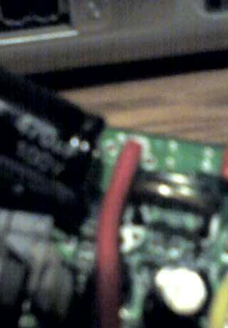
Here are some (bad quality) cell phone pics of the shunt. Maybe you can get an idea of how to go about the mod from these. Sorry for the grainy quality but my digital camera is out of batteries, so I just used my cell phone. :D These pics are of my 72v controller. On this board the shunts are near one end. On the xb 600 controller, the shunts are kinda in the middle, but they look the same. These pics show the new(bigger, gold) shunt and the old(smaller, silver) shunt(s).
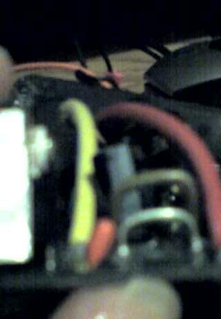
This is another angle of the shunts. Notice the size difference.
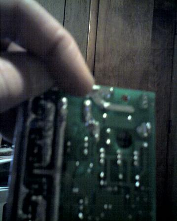
And finally, this is the back. Can you see my BIG BLOB of solder? LOL
Hope this helps. :)
Keep the rubber side down and the shiny side up.
Hi gang -
I thought I'd give you guys an update about how my conversion is going.
I finally got the rest of the conversion done and all I have to say is WOW! This thing can really accelerate now! I accelerate so fast if I crank the throttle I want to slide off the seat!
My bike hasn't gone as fast as 30 yet, but then again, I didn't start with a fresh charge.
Unfortnuately, I'm sad to report that thus far, my experience with the 12ah battery is a bit disappointing, and I'm considering returning it and going with a 20ah batt. On the way to work this morning (an 8 mile drive) the bike slowly went from 60v to 48v as the booster battery drained, so that, by the 6th mile, I was only going 20mph. It's possible (even probable) that the factory charge on the battery wasn't as deep as I will get when I charge it at home, and that my commute will be better next time. If not, I'm definately upgrading the battery.
That said, the scooter (with all batteries charged) performs exactly like the 50cc gas moped I had when I was a kid. It was really nice to be able to keep up with traffic for the first leg of my journey this morning.
A possible problem could be the shunt that I used is actually too conductive. using a coathanger somehow didn't seem right, so I used an inch of 16 gauge copper wire.
Zerogas; was your experience with the acceleration as dramatic as what I'm describing?
Finally, I put a video up on YouTube showing how I did the wiring on the bike. This doesn't show the shunt, but it shows how I did the leads.
http://www.youtube.com/watch?v=TpA9l5GPb8s
Best Regards,
-Mark Milley
[url=http://www.markmilley.com/scooter/]Check out my up-to-date savings and ROI![/url]
Mark,
If you didn't charge the 5th battery before use, it is not atypical for it to die fast like that. Mine did too. However, since then I've had no problems. Like I said, the 5th battery does get drained a little more than the pack, but that's because it is a 12ah battery. It's to be expected. On the other hand, it should last well over 6 miles. I drive 6-8 miles to and from work and I've never had mine go down on me like that. If it still does it after a recharge, recheck your wiring and shunt. But I think what you have here is the classic "shelf battery charge syndrom". LOL Really I think that's all it is, because mine died really fast the first day I did this mod, luckily I was on my street. Also, I didn't get 30mph that first day. It was after I charged that night that "HOLY CRAP"!!!! Fresh off the charge my xb 600 is a beast. :D Hope you get it figured out.
Good Luck,
Warren
Keep the rubber side down and the shiny side up.
Hey Gus,
Do your wiring like Mark did. That's way easier than I did it. I'd still open the pack and check the connections though. I did find 2 that weren't even finger tight when I was doing the 60v mod.
-Warren
Keep the rubber side down and the shiny side up.
Hey you guys thanks for the pics and updates! I'll be looking forward to looking at the youtube video when I get a chance. Been really busy!
Hey, I did check that gray wire yesterday....plugged and unplugged...there was no difference and I know it makes connection. On the wire and plugs I'm seeing you can't plug it but one way. There are two holes on the female side offset to one side...and the male side has one pin. If you tried turning it 180 degrees there would be no hole lined up so the plug would go together. Plus that rocker clamp thing common on these type plugs that hold the connection together...and the nipple it clips over on the other plug are only on one side of the plug. I suppose if you bent the pin it might go together. But anyway, mine was plugged correctly and so I knew it must not be causing any difference. But like I said I tried it anyway...and no difference in speed. I'm thinking the guy at xtreme is just mixed up on this!
This afternoon a guy came by my workplace...vendor...and he saw my scoot and of course had questions...etc. I let him ride it around the parking lot and once again there was another EV convert! I love seeing that smile that comes on their face when they zip around, whisper quiet...and gas free! Wonder how big that smile would have been with the shunt and 60 volt mod!!!!! :-)
Later...
Gushar
Gus
Hi Warren -
Okay, so if I thought my ride to work was bad, it was nothing compared to the ride home.
I got about 2 miles away from the office when the charge was all about dissipated complete from the bike, so I had to push it home the last 6 miles. Whee! 1.5 hour commute, the bulk of that on foot, pushing a 200 pound bike.
Ah well. Dispite the blisters on my feet, I'm viewing this as a minor setback in my quest for a cheap commute.
Granted, none of the batteries were charged to full capacity when I left, but I think something else is going on here. I've decided to blame the shunt.
Now, if you remember, I didn't use a piece of coathanger for my shunt; I used a small piece of 16 gauge wire; I think that the coathanger provided more resistance, and therefore, allows you to accellerate slightly slower and therefore get slightly better range. I also suspect that, given my route to work has a lot of stop signs, this constant stop-and-start drained the batteries very quickly.
So, call me crazy, but here's what I'm thinking. If the bike is 60v strictly because of the extra 12v batt, and the shunt only contributes to faster acceleration/easier power draw by that hungry motor, I've been considering changing the shunt to a switch. In otherwords, I'd put a long line of 16g wire on each end of the shunts on the controller board, and wire them up to a pushbutton on the handlebar near the throttle. You need the extra amps to take off across a busy road or go up a hill? Hold in the button as you accelerate, then release the button when you get up to speed. Otherwise, suffer through the slow acceleration, but enjoy the extended range and faster speed that the extra 12v battery is contributing.
The question I have for you, fellow volt-heads, is--will it work?
...Only one way to find out!
I've also decided to (especially after my experience today) to return the 12ah and get the 20ah battery.
Cheers,
-Mark
[url=http://www.markmilley.com/scooter/]Check out my up-to-date savings and ROI![/url]
Pages