I am finding the monitoring of real-time cell data to be very helpful.
Other than PakTrakr, is there another popular data-gathering device/system that my "graphing" program should support?
If so, and you have a system that you are willing to test with, let me know the (serial, COM port?) data format (first PM so we can chat) and then email a typical log file to me.
The PakTrakr systen has basically one live (and log-file) data format (with the PTES1 or PTES1R serial interface cable), and allows a "download" of data logged in the 2 MB Flash Memory of the ES1R cable.
About 300 bytes are logged for each 21-cell reading, with readings being taken once per second. I currently support up to 3 PT Remotes (24 cells), but the PT system can support 5 Remotes (a max of 40 cells).
I am thinking of making a limited-function version of my PTMonitor available for others to use. Possibly it would be a "PTViewer" only, and read and graph a log file only, and not do the real-time monitoring. But, then one would not have to use Excel or other graphing spreadsheet program to "see" the PT data.
The full version I might offer for sale, if there is any significant interest or demand, and I can find a way to key-activate it to individual computers.
Ideas or suggestions, Please?
Cheers, Gary
XM-5000Li, wired for cell voltage measuring and logging.
I have asked X-Treme what to do to avoid cell damage with the possible cell over-charging that I observed on the first charge of my 5000Li.
I suggested that it might be necessary to "shunt" off some of the charge in the highly-charged cells while the TS charger takes the weekend (or many days) to "bring up" the low cells.
We will see what they suggest.
I am building a simple "shunt" circuit for each of the 21 cells, just in case they suggest using one.
If they allow the simple "bleeding" off of excess charge, while doing normal charging with the "smart" TS charger, that would appear to be a great way to get all the cells "equalized" during charging.
Indeed, are there ANY other low- or reasonable-cost alternatives to keep from over-charging (other than ignoring the problem, which I suspect will not work)?
Cheers, Gary
XM-5000Li, wired for cell voltage measuring and logging.
While I was riding (after 301.4 miles on the odometer), power to the motor stopped. At first, when I twisted the throttle, I could get some intermittent power. However, after about 100 feet. There was no power to the motor.
The volt gauge indicates a full charge.
The red light (lower right on the dash) is on.
All lights are working.
All diagnostic lights are off.
I switched the circuit breaker off and on a couple of times.
Any ideas on diagnosing which part is causing the power failure?
It is the circuit breaker that goes to the motor. If I apply slight pressure to the circuit breaker switch (throttle off, motor not turning) I get voltage. When I release the pressure, the voltage stops.
Henry,
The red-light just means that the 12-volt power ON.
No Diagnostic #1 light means that the brake-light circuit is NOT activated.
That is also the motor-cutoff circuit to the controller.
Three things activate it, the brake handle (applied) switches,
the kick-stand (down) switch, or the motor over-heated switch.
But, sounds like you have a flakey (or possibly overheated) Circuit Breaker.
Make sure you turn the Circuit Breaker fully OFF (to reset
the breaker) before turning it back ON.
Cheers, Gary
XM-5000Li, wired for cell voltage measuring and logging.
Here is the inside of the circuit breaker. I identified the burned areas (red lines). I thought that circuit breakers were basically composed of a bi-metal strip. :-)
There are no burn marks near the In or Out terminals. The only anomaly I see was the blackened and pitted contacts.
I'm hoping that the circuit breaker is defective and that this is a one time occurrance. X-Treme is replacing the circuit breaker under warranty. I think I would like to have a spare in case this happens again.
I was not doing anything different than I did on the XM-3500Li (except go faster). I did record (when I was measuring min/max amperage) that the max amp was slightly above 100 amps. I wonder if a 101 amp circuit breaker would resolve the problem. I also noticed that the circuitry was more complicated than I imaged. I wonder if a 100 amp AC breaker could be used as a replacement. I do not know what the difference in charactistics are between an AC and a DC circuit breaker.
The pitted contacts would be the result of interrupting "too much" current (too often) or having high spikes of current when the contacts are closing, possibly along with "bouncing" (they should not) contacts.
Please keep us posted.
I attempt to have everything turned OFF before I turn OFF the Circuit Breaker.
I just got the PakTrakr Current Sensor hooked up, and I will try to see if I can detect any surges when the Circuit Breaker is switched ON.
Cheers, Gary
XM-5000Li, wired for cell voltage measuring and logging.
I had the breaker burn out quite similarly (more melted plastic then that, actually) on my 3500Li. I'm very sure the problem was just that the wire was loose and current passing through the vibrating wire like that just produced a lot of heat and blew it all out. I got a replacement and after making absolutely certain that the wire was in the terminal nice and tight everything has been fine for me.
I wonder if the circuit breaker is underrated for the application. At 100 amps of current, even a small amount of contact resistance will result in signicant power dissipation. For example, 1 milliohm at 100 amps is 10 watts of power dissipation which could be damaging to the circuit breaker if the heat can not be dissipated fast enough. When the new circuit breaker arrives, it would be a good data point to measure its resistance.
I also had loose connections on the circuit breaker on the XM-3500Li, which I tightened. When I received the XM-5000Li, I checked for loose connections. Both connections to the circuit breaker were tight.
I measured the resistance to be 0.1 ohms on the circuit breaker. I noticed when the speed switch is on high and and I hold the throttle on full (ensuring the back tire can not touch the pavement) there is a pulsing type of sound as the wheel turns. Like on-off-on-off etc. If a back-off the throttle just slightly I do not get the sound. Also I do not detect any lack of power at full throttle when the XM-5000Li is in motion.
I noticed when the speed switch is on high and and I hold the throttle on full (ensuring the back tire can not touch the pavement) there is a pulsing type of sound as the wheel turns. Like on-off-on-off etc. If a back-off the throttle just slightly I do not get the sound. Also I do not detect any lack of power at full throttle when the XM-5000Li is in motion.
Hi Henry,
I noticed this on my 5000 as well. It appears to be an over-speed cut-off for the motor. I've not noticed it on the road.
Hey Gary-- I am wondering if you have received your new lights yet? Which ones are you replacing and do they fit and work? I am waiting to hear from you because I will do the same as you, replace the brake/tail light and the 4 turn signals too, do those fit in the reflectors? and last but not least does the flasher unit have enough load on it to work? Thanks so much for all that you are contributing on this forum....Mikie
While we wait for Gary I'll give you a picture. :)
The pair with the heat sink are the Eagle Eye Tower with 11 LEDs - 10 around the sides and a single 3W in the center. The remaining odd bulb is the SMT Tower 60 with 48 on the side and 12 on the end. Note the custom lamp holder. :-)
Here's a look at before/after current draw (measured at the front brake inhibit switch):
Current draw with three stock incandescent 1157 bulbs: 13A peak, 4.8A continuous
Current draw with three LED 1157 bulbs: .7A peak, .7A continuous
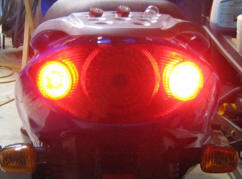
It was difficult to compare light intensity, but here's my best shot without a light meter. The right light in both instances is the stock incandescent.
SMT60 on the left:
Eagle Eye on the left:
I'm using the SMT 60 in the center and it REALLY fills the reflector. The Eagle Eyes do a great job on the side lights but might not be quite as bright as the incandescent.
In the real world - without the camera - I cannot see any individual LEDs - these lamps completely fill the reflector and lense.
A 3.7 v average is not good. One cell at 2.7 and another at 4.7 would be a 3.7 average.
What you want (of course you know) is all cells at the same near-full State of Charge (SOC, or "fullness"), all near "full".
If one starts with the cells nearly balanced, the 5000Li TS smadt pulse-charger MIGHT keep the cells balanced, we are not sure.
Starting with the cells not balanced, as delivered, it APPEARS that the TS charger would be likely to overcharge the higher cells. We have not wanted to sacrifice our own batteries to do the test.
Without a BMS type function to protect each cell from overcharging, it seems unlikely that any two-wire "Pack-Charger" can avoid over-charging a high cell.
Using a voltage-activated shunt to bypass charging current (or other protection) seems to be a necessity. A simple half-amp shunt used with the TS charger seems to do a good job as long as the imbalance is not too large. With a large imbalance, the initial 14-amp charging could still over-charge a high cell.
Manual charging of single low cells will help (but would void the battery warranty), so manually discharging high cells before doing any "pack" charging might be necessary.
However, adding the required 22 wires to the 21 cells, just to be able to CHECK the cell voltages is a SIGNIFICANT job, and might possibly (hopefully not) void the warranty. Monitoring and checking the voltages does not change the way the cells are charged with the TS charger.
What I meant when I asked this was are your cells all being charged up to and staying at around 3.68v to 3.7v using the new BMS. I haven't had a chance to use my G/F BMS yet but I did fully charge all cells individually and then charged them with the TSL72-15. What I have noticed is if you leave the charger on after both lights are green after awhile it will turn on again and go off and so on. If you let it do this for a long time(overnight) it will turn on and off rapidly and both lights will turn red. Do you know what the charger is doing at this point. All I know is if you let it do this(overnight) it will charge all cells above the 3.38 to 3.4xv they usually rest at and they will stay at that higher voltage (3.6x to 3.7) I haven't checked to see if I'm getting better range or not by doing this but I also noticed that now with my cells well balanced the old BMS I made from the commonsence rc balancepro cards keeps the high cells from going over about 4v(during charging). But mainly I wanted feedback on the G/F BMS.
2008 XM3500li Mods/Kelly KBL12251/84v 28cell 40AH pack/ Variable regen brake trigger on left brake handle/Givi/Cycle Analyst/Homemade BMS
KMX Typhoon Home build (recumbent pedelec) with two Astro Brushless 3220motors/twin castle Phoenix ICEHV 160/ Cycl
What I meant when I asked this was are your cells all being charged up to and staying at around 3.68v to 3.7v using the new BMS.
Absolutely! My cells come in between 3.65 and 7.2 after a charge - this is the range of the G/F BMS shut tolerance.
I haven't had a chance to use my G/F BMS yet but I did fully charge all cells individually and then charged them with the TSL72-15. What I have noticed is if you leave the charger on after both lights are green after awhile it will turn on again and go off and so on. If you let it do this for a long time(overnight) it will turn on and off rapidly and both lights will turn red. Do you know what the charger is doing at this point. All I know is if you let it do this(overnight) it will charge all cells above the 3.38 to 3.4xv they usually rest at and they will stay at that higher voltage (3.6x to 3.7) I haven't checked to see if I'm getting better range or not by doing this but I also noticed that now with my cells well balanced the old BMS I made from the commonsence rc balancepro cards keeps the high cells from going over about 4v(during charging). But mainly I wanted feedback on the G/F BMS.
The shunts are only 1/2A, so they can't keep a cell from rising above 3.7V if the charger is pushing more current than that, so it's normal for cells to rise up to 3.8V to 4.3V when the charger is actively pushing. Once the charge current stops, the cells are 'shunted' back down to between 3.65-3.72V.
The charger seems to have three stages - high current charging to 80 or 90%, a period of two minute pulses of 1.8 to 2A spaced every 20 minutes. In this 'pulse and glide' phase, the charge light is green - the fan comes on, the 2A charge pulse happens, and the fan shuts down - all with a green light.
The flashing red light, sometimes with a flash pattern, and what sounds like clicks of relays inside the charger, seems to happen once the pack hits the 'max voltage' stage. The charger will not come out of this phase - this seems to be the way the charger signals that it's done.
Thanks Andy, That's what I thought. My bike is wired with XH connectors(for balancing) that are used in Hobby RC batteries so I had a little trouble getting the female connectors to wire the BMS with. I was going to switch to the value-lock but since I have a hyperion balancing charger I thought I should stick with what I have. If my TSL charger dies I would still be able to charge using the hyperion. So I guess with the BMS you could just use a constant rate charger. I'm now running 28cells. I installed battery isolator switches to take the 4cells I can't charge with the TSL72-15 out of the loop for charging with a 4cell lifepo4 charger. If anyone has a better idea please let me know. The 4cell charger takes a little longer than the TSL to finish charging (about an hour) but it does the job. It's a 10amp charger so at 10amps for 4cells you would think it would charge faster than the TSL at 15amps for 24cells...go figure.
3064km and going 54mph on a 28cell 3500li GPS tested-Bill
PS I ordered the 1amp shunts because I figured that 15amps devided by 24cells=.625amps per cell so the 1amp shunts should be able to keep up with the c/c mode of the charger. I'll let you know how it works.
2008 XM3500li Mods/Kelly KBL12251/84v 28cell 40AH pack/ Variable regen brake trigger on left brake handle/Givi/Cycle Analyst/Homemade BMS
KMX Typhoon Home build (recumbent pedelec) with two Astro Brushless 3220motors/twin castle Phoenix ICEHV 160/ Cycl
It is NOT 15 amps (or whatever the series-charging current is) divided among the cells. EVERY cell in the series string of cells gets the full current, in this case 15 amps.
Thus, the 10-amp charger is slower than the 15-amp charger.
Of course, the "15-amp" charger might not put out quite 15 amps even when in its "maximum" charging mode, and this "smart" TS charger will drop to much lower charging currents when it thinks that it is getting the Pack nearer to "full".
Have you actually seen the TS charger "stop" charging and turn itself OFF?
I have only seen it stop charging with a red 3-flash blinking (some undescribed error) power light. Otherwise, it seems to want to continue charging at a very low rate (some small fraction of an amp average) with the highest cells still climbing.
Cheers, Gary
XM-5000Li, wired for cell voltage measuring and logging.
I replaced my turn signals with LEDs and they work. Truck stops usually have a good variety of LEDs at low prices. Another good thing to do is replace the small single headlight with an LED unit so you can turn off the mains during the day and still be legal (I think) I had to install a switch on my 3500li to do this as there is no on/off switch for the 3500li main lights.
3064km on 24cell 3500li now trying 28cells...so far so good(about 200mi so far). All stock equipment otherwise.
2008 XM3500li Mods/Kelly KBL12251/84v 28cell 40AH pack/ Variable regen brake trigger on left brake handle/Givi/Cycle Analyst/Homemade BMS
KMX Typhoon Home build (recumbent pedelec) with two Astro Brushless 3220motors/twin castle Phoenix ICEHV 160/ Cycl
It is NOT 15 amps (or whatever the series-charging current is) divided among the cells. EVERY cell in the series string of cells gets the full current, in this case 15 amps.
Thus, the 10-amp charger is slower than the 15-amp charger.
Of course, the "15-amp" charger might not put out quite 15 amps even when in its "maximum" charging mode, and this "smart" TS charger will drop to much lower charging currents when it thinks that it is getting the Pack nearer to "full".
Have you actually seen the TS charger "stop" charging and turn itself OFF?
I have only seen it stop charging with a red 3-flash blinking (some undescribed error) power light. Otherwise, it seems to want to continue charging at a very low rate (some small fraction of an amp average) with the highest cells still climbing.
I see. I didn't know that. The 10 amp charger also goes into a pulse mode when near full charge and steps down the amperage. To answer your question, no I have never seen the TS charger actually turn itself off. The nice thing is now with all my cells reaching a full SOC the high cells are not being driven up to 4.3v anymore (they don't go over about 3.9x). My hobby balance cards only shunt 150mah of current I'm sure they're helping but I haven't seen what it would do without them connected. From what you say I guess they would still stay within specs without the cards. I think I'm done modifying though. I'm satisfied for now. I would like to start all over with a better quality glider though.
2008 XM3500li Mods/Kelly KBL12251/84v 28cell 40AH pack/ Variable regen brake trigger on left brake handle/Givi/Cycle Analyst/Homemade BMS
KMX Typhoon Home build (recumbent pedelec) with two Astro Brushless 3220motors/twin castle Phoenix ICEHV 160/ Cycl
I got the 1157 (tail/brake) 45-LED tower (in red) from AutoLumination.com and they are a bit weak, and ... will not work properly in the 5000Li.
1. These "simple" LED bulbs, when driven by the tail light input (in CA we have to drive with the lights on), output sufficient power through the brake input that the motor-shutoff circuit is activated. Thus, you can only "go" with the lights off. Yes, adding a single diode to the 5000Li, or a diode to each input of the LED lamps would cure that, but ... make the third problem even worse.
2. The same "simple" design makes these LEDs not work "properly" when used in parallel with conventional bulbs.
3. They are substantially dimmer than the standard bulbs.
So, I will send these back and buy the 60-LED "patented" Tower lamps (might be the same physical size), which apparently handle each input totally seperately. They are more expensive, but are reported to put out a lot more light.
Using LEDs for the turn signals:
1. Did you replace all four?
2. On the 3500, not the 5000, right?
3. What make, model, part number, or UPC number for the 1156-socket LED lamps?
4. Did you use yellow LEDs?
5. How much did the lamps cost?
6. Others seem to say that the very lightly-loaded "flasher" unit fails to function (properly) when the LEDs are used for turn indicators. Yours (on the 3500) are OK?
Cheers, Gary
XM-5000Li, wired for cell voltage measuring and logging.
After my first charging (long story), I went for a ride on a clear, sunny (79 degree) Sunday late morning. Covering 15 miles up and down hills, some 35 mph, mostly 45, and a bit of 50, I stopped for about 15 seconds before making a right turn ... and no power at all.
The Diagnostic #1 light (motor-cutoff) was on. The motor was over-temperature. I had to push to a safe area (fortunately shaded) and wait for about 30 minutes for the motor to cool enough to continue.
This abrupt no-warning complete loss of power could be a substantial SAFETY issue. How often will this happen on a hot afternoon? Maybe even sooner if I had been going "full throttle"?
Mayby I need to install an override switch to allow me to "drive" to a safe stop?
Because being stopped for 30 minutes every 15 miles is not acceptable, how could one add effective cooling (fins?) to the motor casing?
Ideas or Suggestions?
Cheers, Gary
XM-5000Li, wired for cell voltage measuring and logging.
Gary-- the over ride would be a good temporary idea. I purchased a Infa red thermometer for a hundred bucks. You can shoot it on the left side of the hub(passenger side) to get the external temp and I have heard quoted from an earlier post in this forum that 175 degrees Fahrenheit is the absolute max for the innards of the glue they use in the hub wiring. I would suggest a 130-150 degree outside hub temperature.
Solutions:
A). Carry the I R thermometer
B). Small can of compressed air
C). Smaller can of compressed nitrogen(from pharmacy for wart removal) although this is very cold and I would go slow here
D). Once you get a power back(from the overide) then put up the center stand & run back wheel hub and then use the nitrogen to cool
with this one you should be back on the road at reduced speed in 5 minutes
Gary a great idea is to get the IR thermometer and then do the same thing again to get the temperature that it shuts off at, that is a great starting point to find anyway and it would be useful for all of us for the upcoming summer riding season; in seattle that is between July 30-August 8
best mikie
What I have observed (after the full charge) is that cell 15 (electrically numbered using 1 as positive) is at ~3.4 after a charge, while the rest are at ~3.7. I switched cells 15 and 19 to see if the problem was a weak cell. I'm still observing that cell 15 is at ~3.4 while the others are at ~3.7. I think this is telling me that it is not a weak cell, but something to do with the cell layout. (I did not observe this behavior with the XM-3500Li.
Henry,
Remind me what you are using to measure with.
Your cell 15 would be my cell 7 (counting from 1 at most negative),
and I see no problem with that cell here.
If you use PakTrakr, and have either one of their Serial Cables,
I could send you my PT-Viewer program to look at the log files.
I also have a PT-Monitor program that will gather and graph PT data in real time.
At the moment they will handle up to 5 Remotes (40 cells), and have been used with 3 Remotes.
Cheers, Gary
XM-5000Li, wired for cell voltage measuring and logging.
I got the 1157 (tail/brake) 45-LED tower (in red) from AutoLumination.com and they are a bit weak, and ... will not work properly in the 5000Li.
1. These "simple" LED bulbs, when driven by the tail light input (in CA we have to drive with the lights on), output sufficient power through the brake input that the motor-shutoff circuit is activated. Thus, you can only "go" with the lights off. Yes, adding a single diode to the 5000Li, or a diode to each input of the LED lamps would cure that, but ... make the third problem even worse.
2. The same "simple" design makes these LEDs not work "properly" when used in parallel with conventional bulbs.
3. They are substantially dimmer than the standard bulbs.
So, I will send these back and buy the 60-LED "patented" Tower lamps (might be the same physical size), which apparently handle each input totally seperately. They are more expensive, but are reported to put out a lot more light.
Using LEDs for the turn signals:
1. Did you replace all four?
2. On the 3500, not the 5000, right?
3. What make, model, part number, or UPC number for the 1156-socket LED lamps?
4. Did you use yellow LEDs?
5. How much did the lamps cost?
6. Others seem to say that the very lightly-loaded "flasher" unit fails to function (properly) when the LEDs are used for turn indicators. Yours (on the 3500) are OK?
Gary, To anwer your questions.1.Y 2.Y 3.sorry I know this is the big one but my bike is not here so... Go to an auto parts store and get the amber 4LED lights and NEW sockets for these blade type connectors. Replace the stock sockets with the new ones. I will get part#s but it might take awhile. 4.no amber/orange 5.Don't remember 6.Yes,I guess the 4 LED units are designed for flasher units?
Hope that helps-Bill
PS It's probably not worth the hassle. Someone needs to figure out how to hookup regen... now THAT would be sumpin.
2008 XM3500li Mods/Kelly KBL12251/84v 28cell 40AH pack/ Variable regen brake trigger on left brake handle/Givi/Cycle Analyst/Homemade BMS
KMX Typhoon Home build (recumbent pedelec) with two Astro Brushless 3220motors/twin castle Phoenix ICEHV 160/ Cycl
What I have observed (after the full charge) is that cell 15 (electrically numbered using 1 as positive) is at ~3.4 after a charge, while the rest are at ~3.7. I switched cells 15 and 19 to see if the problem was a weak cell. I'm still observing that cell 15 is at ~3.4 while the others are at ~3.7. I think this is telling me that it is not a weak cell, but something to do with the cell layout. (I did not observe this behavior with the XM-3500Li.
Iccarus: Very interesting on the rmartin. It is exactly what happened to a cell on the XM-3500Li. The charger overcharged the adjacent three cells, before I could figure out what was happening. After the second set (of 4 cells) I decided to use a BMS designed by eped. The overcharging went away and the batteries finally (after several charges) balanced out so that all cells reached ~3.67 volts within a couple minutes of each other. I am about ready to install a BMS (really an overvoltage protection circuit) on the XM-5000Li.
Garygid: I think the cell is fine, it is just that cell 15 charges slower than the others. When I drain the other batteries down to ~3.2 (I think it is a waste of time, especially since this could be solved with a BMS/overvoltage protection circuit) all cells charge to ~3.67. This is occurring before and after I switched #15 with #20 (oops earlier I said #19. It was physically 19, but, electrically 20). If a BMS/overvoltage protection circuit were installed I could let the charger go all night without fear of overcharging one or more cells. I also think I will be saving xTreme-Scooters money since the cell will obviously need to be replaced once I get tired of draining the other cells just to charge the one cell.
Here is the physical layout (numbering). The sequence made since at the time :-)
Front
3 2 1
6 5 4
9 8 7
12 11 10
15 14 13
18 17 16
21 20 19
Back
The first number is the electrical sequence, the second number is the physical number (see above)
1-21 (Positive)
2-18
3- 3
4- 6
5- 5
6- 2
7- 1
8- 4
9- 7
10- 8
11- 9
12-12
13-11
14-10
15-13
16-14
17-15
18-17
19-20
20-19
21-16
Ground

I am finding the monitoring of real-time cell data to be very helpful.
Other than PakTrakr, is there another popular data-gathering device/system that my "graphing" program should support?
If so, and you have a system that you are willing to test with, let me know the (serial, COM port?) data format (first PM so we can chat) and then email a typical log file to me.
The PakTrakr systen has basically one live (and log-file) data format (with the PTES1 or PTES1R serial interface cable), and allows a "download" of data logged in the 2 MB Flash Memory of the ES1R cable.
About 300 bytes are logged for each 21-cell reading, with readings being taken once per second. I currently support up to 3 PT Remotes (24 cells), but the PT system can support 5 Remotes (a max of 40 cells).
I am thinking of making a limited-function version of my PTMonitor available for others to use. Possibly it would be a "PTViewer" only, and read and graph a log file only, and not do the real-time monitoring. But, then one would not have to use Excel or other graphing spreadsheet program to "see" the PT data.
The full version I might offer for sale, if there is any significant interest or demand, and I can find a way to key-activate it to individual computers.
Ideas or suggestions, Please?
Cheers, Gary
XM-5000Li, wired for cell voltage measuring and logging.
I have asked X-Treme what to do to avoid cell damage with the possible cell over-charging that I observed on the first charge of my 5000Li.
I suggested that it might be necessary to "shunt" off some of the charge in the highly-charged cells while the TS charger takes the weekend (or many days) to "bring up" the low cells.
We will see what they suggest.
I am building a simple "shunt" circuit for each of the 21 cells, just in case they suggest using one.
If they allow the simple "bleeding" off of excess charge, while doing normal charging with the "smart" TS charger, that would appear to be a great way to get all the cells "equalized" during charging.
Indeed, are there ANY other low- or reasonable-cost alternatives to keep from over-charging (other than ignoring the problem, which I suspect will not work)?
Cheers, Gary
XM-5000Li, wired for cell voltage measuring and logging.
While I was riding (after 301.4 miles on the odometer), power to the motor stopped. At first, when I twisted the throttle, I could get some intermittent power. However, after about 100 feet. There was no power to the motor.
The volt gauge indicates a full charge.
The red light (lower right on the dash) is on.
All lights are working.
All diagnostic lights are off.
I switched the circuit breaker off and on a couple of times.
Any ideas on diagnosing which part is causing the power failure?
thanks.
It is the circuit breaker that goes to the motor. If I apply slight pressure to the circuit breaker switch (throttle off, motor not turning) I get voltage. When I release the pressure, the voltage stops.
Henry,
The red-light just means that the 12-volt power ON.
No Diagnostic #1 light means that the brake-light circuit is NOT activated.
That is also the motor-cutoff circuit to the controller.
Three things activate it, the brake handle (applied) switches,
the kick-stand (down) switch, or the motor over-heated switch.
But, sounds like you have a flakey (or possibly overheated) Circuit Breaker.
Make sure you turn the Circuit Breaker fully OFF (to reset
the breaker) before turning it back ON.
Cheers, Gary
XM-5000Li, wired for cell voltage measuring and logging.
Here is the inside of the circuit breaker. I identified the burned areas (red lines). I thought that circuit breakers were basically composed of a bi-metal strip. :-)
Is it burned near the In (or Out) terminal?
Does it look like the high-amp connection was not done well
and the connection terminal overheated?
Any words of "wisdom" (or hind sight) to help the rest
of us avoid whatever happened to you?
Cheers, Gary
XM-5000Li, wired for cell voltage measuring and logging.
There are no burn marks near the In or Out terminals. The only anomaly I see was the blackened and pitted contacts.
I'm hoping that the circuit breaker is defective and that this is a one time occurrance. X-Treme is replacing the circuit breaker under warranty. I think I would like to have a spare in case this happens again.
I was not doing anything different than I did on the XM-3500Li (except go faster). I did record (when I was measuring min/max amperage) that the max amp was slightly above 100 amps. I wonder if a 101 amp circuit breaker would resolve the problem. I also noticed that the circuitry was more complicated than I imaged. I wonder if a 100 amp AC breaker could be used as a replacement. I do not know what the difference in charactistics are between an AC and a DC circuit breaker.
The pitted contacts would be the result of interrupting "too much" current (too often) or having high spikes of current when the contacts are closing, possibly along with "bouncing" (they should not) contacts.
Please keep us posted.
I attempt to have everything turned OFF before I turn OFF the Circuit Breaker.
I just got the PakTrakr Current Sensor hooked up, and I will try to see if I can detect any surges when the Circuit Breaker is switched ON.
Cheers, Gary
XM-5000Li, wired for cell voltage measuring and logging.
I had the breaker burn out quite similarly (more melted plastic then that, actually) on my 3500Li. I'm very sure the problem was just that the wire was loose and current passing through the vibrating wire like that just produced a lot of heat and blew it all out. I got a replacement and after making absolutely certain that the wire was in the terminal nice and tight everything has been fine for me.
Lenny Zimmermann
Metairie, LA
I wonder if the circuit breaker is underrated for the application. At 100 amps of current, even a small amount of contact resistance will result in signicant power dissipation. For example, 1 milliohm at 100 amps is 10 watts of power dissipation which could be damaging to the circuit breaker if the heat can not be dissipated fast enough. When the new circuit breaker arrives, it would be a good data point to measure its resistance.
I also had loose connections on the circuit breaker on the XM-3500Li, which I tightened. When I received the XM-5000Li, I checked for loose connections. Both connections to the circuit breaker were tight.
I measured the resistance to be 0.1 ohms on the circuit breaker. I noticed when the speed switch is on high and and I hold the throttle on full (ensuring the back tire can not touch the pavement) there is a pulsing type of sound as the wheel turns. Like on-off-on-off etc. If a back-off the throttle just slightly I do not get the sound. Also I do not detect any lack of power at full throttle when the XM-5000Li is in motion.
Hi Henry,
I noticed this on my 5000 as well. It appears to be an over-speed cut-off for the motor. I've not noticed it on the road.
Andy
Hey Gary-- I am wondering if you have received your new lights yet? Which ones are you replacing and do they fit and work? I am waiting to hear from you because I will do the same as you, replace the brake/tail light and the 4 turn signals too, do those fit in the reflectors? and last but not least does the flasher unit have enough load on it to work? Thanks so much for all that you are contributing on this forum....Mikie
mikie
Hi Mikie,
While we wait for Gary I'll give you a picture. :)
The pair with the heat sink are the Eagle Eye Tower with 11 LEDs - 10 around the sides and a single 3W in the center. The remaining odd bulb is the SMT Tower 60 with 48 on the side and 12 on the end. Note the custom lamp holder. :-)
Here's a look at before/after current draw (measured at the front brake inhibit switch):
Current draw with three stock incandescent 1157 bulbs: 13A peak, 4.8A continuous
Current draw with three LED 1157 bulbs: .7A peak, .7A continuous
It was difficult to compare light intensity, but here's my best shot without a light meter. The right light in both instances is the stock incandescent.
SMT60 on the left:
Eagle Eye on the left:

I'm using the SMT 60 in the center and it REALLY fills the reflector. The Eagle Eyes do a great job on the side lights but might not be quite as bright as the incandescent.
In the real world - without the camera - I cannot see any individual LEDs - these lamps completely fill the reflector and lense.
Andy
What I meant when I asked this was are your cells all being charged up to and staying at around 3.68v to 3.7v using the new BMS. I haven't had a chance to use my G/F BMS yet but I did fully charge all cells individually and then charged them with the TSL72-15. What I have noticed is if you leave the charger on after both lights are green after awhile it will turn on again and go off and so on. If you let it do this for a long time(overnight) it will turn on and off rapidly and both lights will turn red. Do you know what the charger is doing at this point. All I know is if you let it do this(overnight) it will charge all cells above the 3.38 to 3.4xv they usually rest at and they will stay at that higher voltage (3.6x to 3.7) I haven't checked to see if I'm getting better range or not by doing this but I also noticed that now with my cells well balanced the old BMS I made from the commonsence rc balancepro cards keeps the high cells from going over about 4v(during charging). But mainly I wanted feedback on the G/F BMS.
2008 XM3500li Mods/Kelly KBL12251/84v 28cell 40AH pack/ Variable regen brake trigger on left brake handle/Givi/Cycle Analyst/Homemade BMS
KMX Typhoon Home build (recumbent pedelec) with two Astro Brushless 3220motors/twin castle Phoenix ICEHV 160/ Cycl
Absolutely! My cells come in between 3.65 and 7.2 after a charge - this is the range of the G/F BMS shut tolerance.
The shunts are only 1/2A, so they can't keep a cell from rising above 3.7V if the charger is pushing more current than that, so it's normal for cells to rise up to 3.8V to 4.3V when the charger is actively pushing. Once the charge current stops, the cells are 'shunted' back down to between 3.65-3.72V.
The charger seems to have three stages - high current charging to 80 or 90%, a period of two minute pulses of 1.8 to 2A spaced every 20 minutes. In this 'pulse and glide' phase, the charge light is green - the fan comes on, the 2A charge pulse happens, and the fan shuts down - all with a green light.
The flashing red light, sometimes with a flash pattern, and what sounds like clicks of relays inside the charger, seems to happen once the pack hits the 'max voltage' stage. The charger will not come out of this phase - this seems to be the way the charger signals that it's done.
I hope that helps,
Andy
Thanks Andy, That's what I thought. My bike is wired with XH connectors(for balancing) that are used in Hobby RC batteries so I had a little trouble getting the female connectors to wire the BMS with. I was going to switch to the value-lock but since I have a hyperion balancing charger I thought I should stick with what I have. If my TSL charger dies I would still be able to charge using the hyperion. So I guess with the BMS you could just use a constant rate charger. I'm now running 28cells. I installed battery isolator switches to take the 4cells I can't charge with the TSL72-15 out of the loop for charging with a 4cell lifepo4 charger. If anyone has a better idea please let me know. The 4cell charger takes a little longer than the TSL to finish charging (about an hour) but it does the job. It's a 10amp charger so at 10amps for 4cells you would think it would charge faster than the TSL at 15amps for 24cells...go figure.
3064km and going 54mph on a 28cell 3500li GPS tested-Bill
PS I ordered the 1amp shunts because I figured that 15amps devided by 24cells=.625amps per cell so the 1amp shunts should be able to keep up with the c/c mode of the charger. I'll let you know how it works.
2008 XM3500li Mods/Kelly KBL12251/84v 28cell 40AH pack/ Variable regen brake trigger on left brake handle/Givi/Cycle Analyst/Homemade BMS
KMX Typhoon Home build (recumbent pedelec) with two Astro Brushless 3220motors/twin castle Phoenix ICEHV 160/ Cycl
It is NOT 15 amps (or whatever the series-charging current is) divided among the cells. EVERY cell in the series string of cells gets the full current, in this case 15 amps.
Thus, the 10-amp charger is slower than the 15-amp charger.
Of course, the "15-amp" charger might not put out quite 15 amps even when in its "maximum" charging mode, and this "smart" TS charger will drop to much lower charging currents when it thinks that it is getting the Pack nearer to "full".
Have you actually seen the TS charger "stop" charging and turn itself OFF?
I have only seen it stop charging with a red 3-flash blinking (some undescribed error) power light. Otherwise, it seems to want to continue charging at a very low rate (some small fraction of an amp average) with the highest cells still climbing.
Cheers, Gary
XM-5000Li, wired for cell voltage measuring and logging.
I replaced my turn signals with LEDs and they work. Truck stops usually have a good variety of LEDs at low prices. Another good thing to do is replace the small single headlight with an LED unit so you can turn off the mains during the day and still be legal (I think) I had to install a switch on my 3500li to do this as there is no on/off switch for the 3500li main lights.
3064km on 24cell 3500li now trying 28cells...so far so good(about 200mi so far). All stock equipment otherwise.
2008 XM3500li Mods/Kelly KBL12251/84v 28cell 40AH pack/ Variable regen brake trigger on left brake handle/Givi/Cycle Analyst/Homemade BMS
KMX Typhoon Home build (recumbent pedelec) with two Astro Brushless 3220motors/twin castle Phoenix ICEHV 160/ Cycl
I see. I didn't know that. The 10 amp charger also goes into a pulse mode when near full charge and steps down the amperage. To answer your question, no I have never seen the TS charger actually turn itself off. The nice thing is now with all my cells reaching a full SOC the high cells are not being driven up to 4.3v anymore (they don't go over about 3.9x). My hobby balance cards only shunt 150mah of current I'm sure they're helping but I haven't seen what it would do without them connected. From what you say I guess they would still stay within specs without the cards. I think I'm done modifying though. I'm satisfied for now. I would like to start all over with a better quality glider though.
2008 XM3500li Mods/Kelly KBL12251/84v 28cell 40AH pack/ Variable regen brake trigger on left brake handle/Givi/Cycle Analyst/Homemade BMS
KMX Typhoon Home build (recumbent pedelec) with two Astro Brushless 3220motors/twin castle Phoenix ICEHV 160/ Cycl
Sorry for the typo, folks. My cells finish between 3.65 and 3.72 - not 7.2.
Andy
(note to self...lobby for being able to edit on this forum...after remedial proofreading practice...)
I got the 1157 (tail/brake) 45-LED tower (in red) from AutoLumination.com and they are a bit weak, and ... will not work properly in the 5000Li.
1. These "simple" LED bulbs, when driven by the tail light input (in CA we have to drive with the lights on), output sufficient power through the brake input that the motor-shutoff circuit is activated. Thus, you can only "go" with the lights off. Yes, adding a single diode to the 5000Li, or a diode to each input of the LED lamps would cure that, but ... make the third problem even worse.
2. The same "simple" design makes these LEDs not work "properly" when used in parallel with conventional bulbs.
3. They are substantially dimmer than the standard bulbs.
So, I will send these back and buy the 60-LED "patented" Tower lamps (might be the same physical size), which apparently handle each input totally seperately. They are more expensive, but are reported to put out a lot more light.
Using LEDs for the turn signals:
1. Did you replace all four?
2. On the 3500, not the 5000, right?
3. What make, model, part number, or UPC number for the 1156-socket LED lamps?
4. Did you use yellow LEDs?
5. How much did the lamps cost?
6. Others seem to say that the very lightly-loaded "flasher" unit fails to function (properly) when the LEDs are used for turn indicators. Yours (on the 3500) are OK?
Cheers, Gary
XM-5000Li, wired for cell voltage measuring and logging.
After my first charging (long story), I went for a ride on a clear, sunny (79 degree) Sunday late morning. Covering 15 miles up and down hills, some 35 mph, mostly 45, and a bit of 50, I stopped for about 15 seconds before making a right turn ... and no power at all.
The Diagnostic #1 light (motor-cutoff) was on. The motor was over-temperature. I had to push to a safe area (fortunately shaded) and wait for about 30 minutes for the motor to cool enough to continue.
This abrupt no-warning complete loss of power could be a substantial SAFETY issue. How often will this happen on a hot afternoon? Maybe even sooner if I had been going "full throttle"?
Mayby I need to install an override switch to allow me to "drive" to a safe stop?
Because being stopped for 30 minutes every 15 miles is not acceptable, how could one add effective cooling (fins?) to the motor casing?
Ideas or Suggestions?
Cheers, Gary
XM-5000Li, wired for cell voltage measuring and logging.
Gary-- the over ride would be a good temporary idea. I purchased a Infa red thermometer for a hundred bucks. You can shoot it on the left side of the hub(passenger side) to get the external temp and I have heard quoted from an earlier post in this forum that 175 degrees Fahrenheit is the absolute max for the innards of the glue they use in the hub wiring. I would suggest a 130-150 degree outside hub temperature.
Solutions:
A). Carry the I R thermometer
B). Small can of compressed air
C). Smaller can of compressed nitrogen(from pharmacy for wart removal) although this is very cold and I would go slow here
D). Once you get a power back(from the overide) then put up the center stand & run back wheel hub and then use the nitrogen to cool
with this one you should be back on the road at reduced speed in 5 minutes
Gary a great idea is to get the IR thermometer and then do the same thing again to get the temperature that it shuts off at, that is a great starting point to find anyway and it would be useful for all of us for the upcoming summer riding season; in seattle that is between July 30-August 8
best mikie
mikie
What I have observed (after the full charge) is that cell 15 (electrically numbered using 1 as positive) is at ~3.4 after a charge, while the rest are at ~3.7. I switched cells 15 and 19 to see if the problem was a weak cell. I'm still observing that cell 15 is at ~3.4 while the others are at ~3.7. I think this is telling me that it is not a weak cell, but something to do with the cell layout. (I did not observe this behavior with the XM-3500Li.
Henry,
Remind me what you are using to measure with.
Your cell 15 would be my cell 7 (counting from 1 at most negative),
and I see no problem with that cell here.
If you use PakTrakr, and have either one of their Serial Cables,
I could send you my PT-Viewer program to look at the log files.
I also have a PT-Monitor program that will gather and graph PT data in real time.
At the moment they will handle up to 5 Remotes (40 cells), and have been used with 3 Remotes.
Cheers, Gary
XM-5000Li, wired for cell voltage measuring and logging.
Gary, To anwer your questions.1.Y 2.Y 3.sorry I know this is the big one but my bike is not here so... Go to an auto parts store and get the amber 4LED lights and NEW sockets for these blade type connectors. Replace the stock sockets with the new ones. I will get part#s but it might take awhile. 4.no amber/orange 5.Don't remember 6.Yes,I guess the 4 LED units are designed for flasher units?
Hope that helps-Bill
PS It's probably not worth the hassle. Someone needs to figure out how to hookup regen... now THAT would be sumpin.
2008 XM3500li Mods/Kelly KBL12251/84v 28cell 40AH pack/ Variable regen brake trigger on left brake handle/Givi/Cycle Analyst/Homemade BMS
KMX Typhoon Home build (recumbent pedelec) with two Astro Brushless 3220motors/twin castle Phoenix ICEHV 160/ Cycl
Henry, I was just reading some other posts on the rmartin that has 21 60AH cells wired like yours and look what I found check this out http://visforvoltage.org/forum/4841-evd-3000w-wlithium-batteries#comment-30640 seems your not alone...Hmmm you guys should talk, I doubt this could be a coincidence.
2008 XM3500li Mods/Kelly KBL12251/84v 28cell 40AH pack/ Variable regen brake trigger on left brake handle/Givi/Cycle Analyst/Homemade BMS
KMX Typhoon Home build (recumbent pedelec) with two Astro Brushless 3220motors/twin castle Phoenix ICEHV 160/ Cycl
Iccarus: Very interesting on the rmartin. It is exactly what happened to a cell on the XM-3500Li. The charger overcharged the adjacent three cells, before I could figure out what was happening. After the second set (of 4 cells) I decided to use a BMS designed by eped. The overcharging went away and the batteries finally (after several charges) balanced out so that all cells reached ~3.67 volts within a couple minutes of each other. I am about ready to install a BMS (really an overvoltage protection circuit) on the XM-5000Li.
Garygid: I think the cell is fine, it is just that cell 15 charges slower than the others. When I drain the other batteries down to ~3.2 (I think it is a waste of time, especially since this could be solved with a BMS/overvoltage protection circuit) all cells charge to ~3.67. This is occurring before and after I switched #15 with #20 (oops earlier I said #19. It was physically 19, but, electrically 20). If a BMS/overvoltage protection circuit were installed I could let the charger go all night without fear of overcharging one or more cells. I also think I will be saving xTreme-Scooters money since the cell will obviously need to be replaced once I get tired of draining the other cells just to charge the one cell.
Here is the physical layout (numbering). The sequence made since at the time :-)
Front
3 2 1
6 5 4
9 8 7
12 11 10
15 14 13
18 17 16
21 20 19
Back
The first number is the electrical sequence, the second number is the physical number (see above)
1-21 (Positive)
2-18
3- 3
4- 6
5- 5
6- 2
7- 1
8- 4
9- 7
10- 8
11- 9
12-12
13-11
14-10
15-13
16-14
17-15
18-17
19-20
20-19
21-16
Ground
Pages