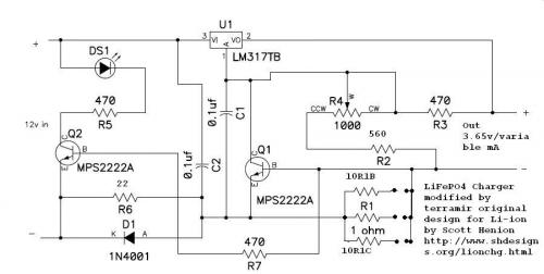
Ok this is the circuit I'm dealing with:
secondly becuase I'm having problems optimizing for space and solder points this is the solution I came up with for the mean time :)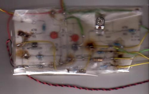
Pathetic ain't it LOL now I tried using this board
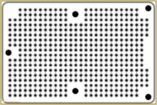
but I'm having some problems doing this I already screwed one charger circuit up, because I'm having problems making it fit in the least amount of space with the least amount of wire bridges. the 3 hole pairs after the resistor are three jumpers that determine the current flow.
Is anyone here a crack at circuit design that could give me a hand?
terramir


terramir,
Well it has been a long time since I designed any circuits, but I can make a couple of comments;
There is only one power component in the circuit, the LM317TB, so place it off board, and on a heat sink. I am sure you already knew that.
All the other components are small low wattage devices which will generate little or no heat. Mount all of the parts vertically on a .1 inch center perforated board, down flush on the board. The whole thing ought to fit in a couple of square inches by an inch high.
Just remember, there doesn't need to be any space between the these low power components, just make sure the wires don't short together. If there is any concern that they might short out under vibration, then just cover the circuit in some sort of epoxy or glue after building and testing it.
Here is a link to an amateur project I found that should give you some pointers on layout. Just take a look at the hand constructed board that is used in this LED torch project, and I think you will see how you can compress your circuit into a much smaller space.
http://www.geocities.com/lemagicien_2000/elecpage/ledtorch/ledtorch.html
This looks like a fun project, I know I had many hours of fun on the olden days when I was building electronic circuits.
Enjoy,
Tom
Yeah if you look at the second pic it's a bit fuzzy but those 3 wires coming off the top are the wires to the LM317T, looked at the website he does some neat things there :p
But I'm still having a problem wrapping my mind around this particular circuit on the particular protoboard I got. Anybody here a crack at circuit wiring check the protoboard I have in the pic above can you picture the circuit in the smallerst space possible then help plox
terramir