Ever wondered about your battery?
I got bored so checked it out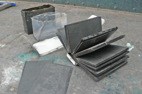
Similar to a lead acid battery , but with many more plates separated by wet electrolytic pads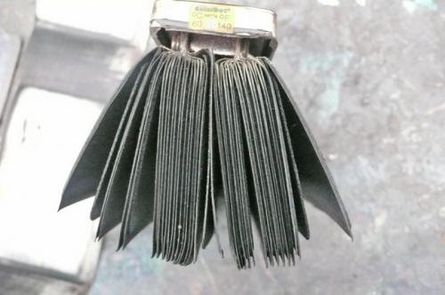
Without the pads between the anode & cathode will short if the cell still has some life in it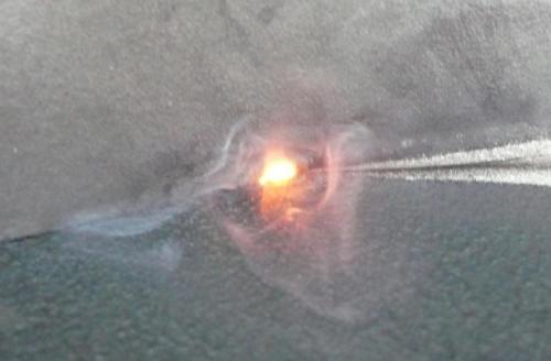
Well that was my "Juslius Somner Miller" moment, now to put it together??
Workings of the GP Cell
Sun, 09/06/2009 - 19:39
#1

Workings of the GP Cell

Who's online
There are currently 0 users online.
Who's new
- Bengun
- Skyhawk 57
- wild4
- justinsmith07
- Juli76
Support V is for Voltage

Very interesting... I can see the main problem of batteries: Lack of investigation...
They are build with the same technology used at end of the 19th century. It's like building an iron bridge using the structural pattern of timbers (wood).... In this case, the great structural capabilities of iron would be simply ignored...
Very nice!
Was is scary and smelly? Bangs and flashes?
This thread has been added to the Vectrix Collaborative Handbook, please stay on topic!
This information may be used entirely at your own risk.
There is always a way if there is no other way!
After I discharged the pack down to 1.20volt/p/cell, I measure voltage
under load, and replaced all those that had the highest voltage drop
Some data on the worse of a batch I took out of the scooter
can anybody tell which is the best cell in this Data, or is a capacity test the only way?
I think this is a cheap method to identify the worst cells in the pack. You will miss any moderately damaged cells and you will not know if all the other cells are still really good or very borderline as well.
Did your method identify any cells as "bad" that were not showing lateral swelling anyway?
The only way to be certain is to fully charge the cells and then capacity test them on the bench individually with a computerized battery analyser. I used a CBA2.
Even my worst cell (16Ah capacity @ 20A to 1.1V cutoff) had the same low internal resistance as all the others (unless when almost empty), but was slightly more swollen.
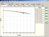
Click on the picture below to see details of it. It shows overlayed graphs of several cells and you can see what I mean by studying the graphs a bit:
For easy, fast and cheap identification of bad cells, just feel for lateral swelling and confirm it visually.
This information may be used entirely at your own risk.
There is always a way if there is no other way!
"Did your method identify any cells as "bad" that were not showing lateral swelling anyway?"
All bad cells in the group where swollen and some three where not,
but will cap. test later
Thanks Mik did you get my email?
Hello Mik
Want to complement you on your dedication working and testing the Vectrix,I do not have one, just several Lepton and using Nickel Zinc pack by Evercel.One of your recent comment got my eye " you where unable to see any difference in internal between the low A/H cell and the high one",my findings are different.Which instrument are you using ?. Been doing a lot work with internal impedance on different chemistries and can usually determine the high A/H from the low A/H by its internal impedance( charged cell and allowed to cool down ).Would love to get the figures from your cells.
I am very impressed by your determination of solving all the batteries issues,would like to contribute to your effort what ever I can,I am willing to lend you one of my HP4328a for as long as you need it, providing that you share in the shipping charges from the USA to Australia.The meter with no internal batteries weight about 8 lbs pack up will be less than 10 lbs,think that it should be less that $25.00.
Also I am looking to visit Australia in the near future ( less than 6 months) would like to connect up with you,would this be possible ?
For the past couple years,have a BMS for the 12 volts NI-Zn pack in the prototype stage,changing it to other chemistries will not be much probleme.
Have you done any work with LifePO4 packs ?.
I can be contacted at abalogh @ hotmail.com .Do you happen to have skyp on your P.C.?
Regards
Andre
HEAT & LOSS & INEFFICIENCY RELATED DIRECTLY to IMPEDANCE
I was in my local RITZ CAMERA shop about 6 months ago, and spotted some rechargeable, Nickel-Zinc cells in "AA size". I purchased some of theses cells for valuation, along with the matching charger. I installed 8 of them into a portable, 2-way radio transceiver, and noted good performance, with a starting discharge voltage for the 8 series connected cells, of about 13.8 volts. This device has a current drain of about 450 milliamperes when listening, and 1 1/2 to 2.0 amperes when transmitting. The cells gave about 3 hours operation, which was not bad, but after about 2 months usage, and fewer than 20 recharges, many cells started showing signs of leakage near the positive terminal, and experienced low capacity. This, I consider, is very poor lifetime, compared to Ni-MH or Ni-Cd cells in the same application. The higher cell voltage was good, the poor sealing/short life was bad! (charged cell voltage was typically 1.8 to 1.9 volts per cell, remaining at or above 1.4 volts per cell for a considerable percentage of discharge.)-Bob Curry
Robert M. Curry
I was wondering where you were and why you did not comment on the lack of IR difference earlier. I pointed this out almost a year ago when I tested all the cells, I need to look up where the details are (probably on Endless Sphere: http://endless-sphere.com/forums/viewtopic.php?f=14&t=6277
The method I used is also described there somewhere. I basically made up a 4 cable device from a DMM and the CBA2, measured at 11 and at 1A drain and calculated the IR from that.
But the IR is also "visible" in the graphs above. All the curves are overlapping until the cell is near empty, then it drops out of the cluster. If the IR was different, then the curve of that cell would run parallel to the rest of the overlapping curves!
The IR at full, half full and 1/4 full of these cells is about 1.5mOhm to 2 mOhm!
It would be nice to meet when you come to Oz! Maybe you can bring that tester along with you? Then you can check if you get the same results.
This information may be used entirely at your own risk.
There is always a way if there is no other way!