Re: How to "improve" a NiMH Vectrix battery before it ...
Hi Mik,
my first reaktion was something like "what the hell..." I opened the links after that and had a big surprise: If yo compare the
two originalcircuits you see they are nearly identical in form and funktion. "Only" difference the one uses transistros to drive
the LEDs , the other uses only LEDs driving themselve. Both circuits have the problem that they are designed to work with only
two battery parts. As I did some testing with the transistor-type, there is a little problem with switching the relais: if they
don´t switch exactly at the same time the circuit reacts and draws much more curent destroying the LEDs, so the next step will be
a constant-curent subcircuit for each LED (with a transistor or a FET (Feldeffekttransistor)).constant curent circuits (german)
Greetings Mike
And I thought I could go to the electronics shop today and buy some parts....too early?
The circuit made from diodes does not work near as well as your transistor circuit (at least in the simulation). There is barely enough current going through the LED's when an imbalance is present. And I had to fiddle with Vf values and don't know how hard it would be to find diodes that work well for it.
In addition, the diodes circuit draws more current and the problem of the middle segment drawing more power is unsolved - unlike in your transistor circuit.
This information may be used entirely at your own risk.
Re: How to "improve" a NiMH Vectrix battery before it ...
...
...As I did some testing with the transistor-type, there is a little problem with switching the relais: if they
don´t switch exactly at the same time the circuit reacts and draws much more curent destroying the LEDs, so the next step will be
a constant-curent subcircuit for each LED (with a transistor or a FET (Feldeffekttransistor)).constant curent circuits (german)
Greetings Mike
Whatever I tried, the current through any of the LED's maxes out at about 20mA. Can they not take this?
The next problem is that I do not understand the specifications used for describing opto-couplers. Could we not just use some type of opto-coupler that is resilient to brief over-current through it's LED?
This information may be used entirely at your own risk.
Re: How to "improve" a NiMH Vectrix battery before it ...
Hi,
I would prefer if we talk about the "transistor-circuit" instead of "my circuit", because I did not design it I grabbed it from the web.
The first source I used was from G. La Rooy, Christchurch,New Zealand Silicon Chip Online. and www.extremecircuits.net
Back to topic:
Mik I changed the values of the resistors for the LEDs, and was checking what happens when the transistors differ in their powerfactor
(hFE-value) some with hFE of 250 some with 450. On the first picture you see how the current changes with different values for hFE. I
did no research yet which transistor would be the right one for this aplication (System-voltage etc...) so I wanted to know what happens
if they differ a lot:
On the second picture we see what happens with a transistor with a higher hFE, the LED is suplied with slightly to much current when the
four relais don´t switch at the same time. The LED or the infrared-LED of the opto-couplers could fail after some time, because of the
higher current.
If we use transistors with a high hFE for efficient driving the leds they would neet a constant current protection with a FET-Transistor
like this below. The circuit on the left side could be used instead the 1,5K resistor that is actualy used for the LEDs. More soldering but
more stable.
Mik you are highly welcome for making a testcircuit as you have a second Vectrix battery for testing. As my V is still in service till end
of October or mid November, I use the time for simulations and "finding the little bugs in there". When it is in its hibernation I´ll be
able to open the battery-bay to attach the circuit and test it by puting various current demands on the three parts of the battery.
Time for bed it´s 01:00 in the morning ;-P
Greetings Mike
Re: How to "improve" a NiMH Vectrix battery before it ...
Hi there,
I checked it again, Mik was right it should work without the constant curent sub-circuit.
At least with 2,5k Resistors and transistors with a good power factor (hFE 250-350)...
After my holiday-vaction I´ll start to solder a prototype.
Greetings Mike
How do we choose the right transistors?
What "Collector-to-emitter-breakdown-voltage" do we need? Minimum 160V, I guess?
This information may be used entirely at your own risk.
Re: How to "improve" a NiMH Vectrix battery before it ...
Hi there,
I checked it again, Mik was right it should work without the constant curent sub-circuit.
At least with 2,5k Resistors and transistors with a good power factor (hFE 250-350)...
After my holiday-vaction I´ll start to solder a prototype.
Greetings Mike
I have had a play with the circuit simulator and found a combination of components that allows to use hFE=50 transistors.
Maybe I misunderstand the specs, but it seems difficult to find transistors with both high voltage and high hFE specs.
Re: How to "improve" a NiMH Vectrix battery before it ...
Hi Mik, I had a look on it. Very good and fast response to voltage-imbalance.
Just the standby current gain is rather high. Maybe we find transistors "in between".
I checked the voltage of the 6 transistors the never reached 50v in any case, so we
maybe can work with that value. I´m looking for transistor listings in the web to
find "the right one" easier. Just checking "http://www.tonband.net/tech_trans.php"
maybe I finde something there.
To the others maybe someone has a pdf or a link with many transistors to compare at
one look?
Re: How to "improve" a NiMH Vectrix battery before it ...
Hi Mik, I had a look on it. Very good and fast response to voltage-imbalance.
Just the standby current gain is rather high. ...
...
I figured that 30-40mA current drain does not matter much - as long as it is automatically shut down when the scooter is turned off.
It only takes one hour to drain the battery while riding at reasonable speeds, so 40mA causes a "loss" of 0.04Ah of usable capacity during a discharge.
0.04Ah / 30Ah = 0.1% range reduction.
If it was a constant drain (like the 7mA constant-on stock-MC), then you would get 0.04A x 24hrs x 30 days = 28.8Ah drain per month - almost the entire battery capacity!
I just want to use the IDeA during riding and during automated deep battery discharges/exercise cycles. The current drain of the IDeA does not matter in those circumstances. Even if we find a use during charging, the charge current of the lowest suggested EQ-charge current (the original Freddy with 8uF / 0.3A) is almost an order of magnitude larger than the current drain of the IDeA. 40mA is a small price to pay for simplicity and sensitive accuracy!
We need someone with the know-how, like The_Laird, to explain how to choose the rights specs for the components, particularly the transistors. Ideally this should be designed so that it passes any reasonable national electrical safety regulation and can be used/sold/built anywhere world-wide. So the safety margins should be wide, if possible.
Of course, if we can find a solution that uses low standby current that would be preferable. After all, the Vectrix is definitively not the only EV that might benefit from this. There may well be situations where constant-on IDeA is needed.
It may of course also turn out to be a total flop, due to some fact we forgot about, or that only rears it's head during real life EV usage conditions...
But for now I choose to feel confident that we may be finding a way to improve the (outstanding) performance of NiMH batteries further.
One of the prime uses for an IDeA would be to help keeping marginally damaged batteries running for much, much longer.
It's all about looking after the weakest cell.
This information may be used entirely at your own risk.
Re: How to "improve" a NiMH Vectrix battery before it ...
I figured that 30-40mA current drain does not matter much - as long as it is automatically shut down when the scooter is turned off.
It only takes one hour to drain the battery while riding at reasonable speeds, so 40mA causes a "loss" of 0.04Ah of usable capacity during a discharge.
0.04Ah / 30Ah = 0.1% range reduction.
I did see the trees not the forrest ;-)
I did some research to find transistors I can get at a local store, but a printed active component data-booklet is on my wishlist now.
I can get the components at my local store (www_C0nrad_at) the types are: PNP high-voltage transistor 2N5401 and NpN Version 2N5551.
Both have a maximum collector-emitor voltage around 160V and a powerfactor(hFE) around 60 at 10mAh. They are rather small and cheap and
handle up to 100mAh which should be enough for this aplication. Next step will be the relais and the optoisolators.
Greetings Mike
Re: How to "improve" a NiMH Vectrix battery before it ...
Hi Turok, thanks.
Unfortunately my warranty is over this month. On the other hand I´m soon able to test it when the bike is in it´s
hibernation and on the bench... But you have to wait at least till early november, because I´m on holliday beginning
this weekend till 26. Okt. As me and my girlfriend leave the continent I won´t push this project forward until I´m
back.
How to fuse anything extra connected to the battery.
Before connecting anything to the battery one needs to carefully consider how to fuse it. This is particularly so for any prototype devices that might not work exactly as intended!
So how should that be done?
If any connections to the middle and lower layer of the battery are required, then it gets particularly tricky, because of the space restrictions within the battery.
Any fuses including the fuse holder must be small enough to not impede the cooling air flow through the battery.
Any fuses must be appropriately DC rated - if not, then an arc of ionised gas can form when the fuse wire melts and thus sustain the current flow.
The fuses should ideally be located right at the battery connection.
Any suggestions?
This information may be used entirely at your own risk.
Re: How to "improve" a NiMH Vectrix battery before it ...
I have played around a bit with simulations for optocouplers to be used instead of the LED's in the transistor IDeA circuit.
But I keep running into a problem - and don't know if it is a software error or a n actual problem in the circuit.
I simulated the 12V SMPS with a relay to isolate the 140VDC from the 12V DC part, but the same problem keeps occurring.
The circuit shown below shows one simulated optocoupler, represented by a switch and a transistor. When the switch is closed, the LED in the optocoupler is "ON", meaning imbalance detected. This lights the red LED when the Vectrix key is in the "ON" position or if the charger is running, but does not stop anything else.
The screenshot below shows a no-imbalance situation when the key is turned off but the SMPS remains powered up. The "Impeller motor" is represented by a 2.5 ohm resistor and disconnected (because that's what causes the problem).
The next screenshot shows a situation with key "ON" and imbalance detected. A red LED is lit (will eventually be on the dashboard, nothing else stops):
When the Vectrix key or charger (represented by a switch) is off, then the optocoupler turns the SMPS off if imbalance is detected (This will one day be the deep-discharge shutdown function.)
Now to the problem: When I add the 2.5 ohm resistor into the simulation to represent the impeller motor, it stops working when the key switch is opened. The program gives an error message: " Convergence failed!"
0.02 99.2
w 176 192 144 192 0
w 272 176 272 112 0
w 272 112 256 112 0
162 416 336 416 288 1 2.1024259 1.0 0.0 0.0
r 416 336 416 384 0 910.0
w 416 384 416 464 0
w 480 240 416 240 0
w 416 240 416 288 0
w 400 240 416 240 0
w 144 112 144 128 0
w 144 192 144 176 0
r 176 192 240 192 0 7100.0
w 256 112 192 112 0
v 576 464 496 464 0 0 40.0 12.0 0.0 0.0 0.5
v 880 256 880 192 0 0 40.0 12.0 0.0 0.0 0.5
178 736 416 736 464 0 1 0.2 0.032784426146908525 0.05 1000000.0
0.02 300.0
w 144 176 144 128 0
d 480 464 480 400 1 0.805904783
d 608 400 608 464 1 0.805904783
d 480 240 544 240 1 0.805904783
w 608 400 608 384 0
w 608 384 688 384 0
w 688 384 688 416 0
w 704 352 704 416 0
w 704 352 608 352 0
w 720 464 720 240 0
w 608 304 608 352 0
w 688 384 688 272 0
w 688 272 544 272 0
x 78 46 186 52 0 24 Simulated
x 67 68 200 74 0 24 Optocoupler
x 470 336 605 342 0 24 Key/Charger
w 608 352 576 352 0
w 480 400 480 352 0
w 480 352 496 352 0
w 576 464 608 464 0
w 496 464 480 464 0
x 73 89 191 95 0 24 firing when
x 69 113 139 119 0 24 closed
x 910 236 998 242 0 24 140VDC
x 447 214 683 220 0 24 12VDC ABCool SMPS
w 736 416 736 352 0
x 478 503 620 509 0 24 12VDC Stock
s 432 176 480 176 0 0 false
d 544 176 480 176 1 0.805904783
w 544 272 480 272 0
w 480 272 480 240 0
v 592 176 544 176 0 0 40.0 12.0 0.0 0.0 0.5
w 880 256 880 352 0
w 880 352 736 352 0
w 720 240 720 208 0
178 640 96 640 176 0 1 0.2 -0.17660044143126302 0.05 1000000.0
0.02 67.9
w 624 176 592 176 0
w 640 96 688 96 0
w 688 96 688 240 0
w 688 240 544 240 0
w 880 192 880 64 0
w 880 64 592 64 0
w 592 64 592 96 0
w 608 96 608 80 0
w 608 80 720 80 0
w 720 80 720 208 0
w 432 176 400 176 0
d 480 304 544 304 1 0.805904783
w 544 304 608 304 0
w 384 416 272 416 0
w 272 416 272 208 0
w 448 464 464 464 0
w 464 464 464 304 0
w 480 304 464 304 0
w 400 416 400 400 0
w 400 400 384 400 0
w 384 400 384 240 0
w 384 240 400 240 0
w 432 416 448 416 0
w 448 416 448 192 0
w 400 176 400 192 0
w 400 192 448 192 0
w 400 176 336 176 0
x 281 275 379 281 0 24 Impellers
w 288 240 288 176 0
w 336 176 288 176 0
w 288 176 272 176 0
r 288 240 368 240 0 2.5
x 437 149 486 155 0 24 OFF
x 360 493 441 499 0 24 Relay 1
x 686 498 767 504 0 24 Relay 2
x 556 53 808 59 0 24 Relay simulating SMPS
s 496 352 576 352 0 1 false
s 144 112 192 112 0 1 false
o 16 64 0 33 10.0 0.2 0 -1
o 28 64 0 289 10.0 0.05 1 -1
o 6 64 0 289 5.0 0.0125 2 -1
Paste this code into the applet and click the switches until it all makes sense...then add a bit of wire to close the 2.5 ohm resistor into the loop and try again to replicate the "Convergence failed!" error.
Any idea why this happens?
This information may be used entirely at your own risk.
Re: How to "improve" a NiMH Vectrix battery before it ...
Now to the problem: When I add the 2.5 ohm resistor into the simulation to represent the impeller motor, it stops working when the key switch is opened. The program gives an error message: " Convergence failed!"
Re: How to "improve" a NiMH Vectrix battery before it ...
...
An unsolved issue is so far that the IDeA will not turn off automatically when the key is turned off. But that should be easy enough to implement.
Fixed! The simulation is really starting to come together now:
The above shows the IDeA system during detection of an imbalance while riding or charging with the IDeA turned off.
The cooling impellers are switched on and the Deep Discharge system is switched off. The impellers can also be switched off (or rather: handed back into the control by the stock system). Apart from the optional permanent on for the impellers everything keeps running as controlled by the stock system, but a red LED lights up on the dashboard when a single cell reverses. Once the key is turned off (or the charger turns off the auxiliary 12V supply), everything turns off. No additional residual current drain!
If the IDeA system is fully turned on, then it will continue to run (even when the charger is off and the key is in the off position) until the battery is so empty that the first cell reverses. Then everything shuts down (except for the stock systems 7mA power drain). This could also be controlled by an additional timer to allow cooling after riding or while parked in the sun away from the grid.
If the impellers are running during such a deep discharge (while parked!), then about 350mA would be drained from the battery to drive the impellers - until the first cell reverses.
Re: How to "improve" a NiMH Vectrix battery before it ...
Here is one of my questions on how to build this simulated circuit:
1) What minimum voltage rating do I need to use for the transistors (for collector-base, collector-emitter and emitter-base voltage)?
Each segment of the battery being measured has a maximum voltage of 51V. But the whole battery has a maximum of 153V.
Do I need to use transistors rated for >51V or for >153V? This maximum voltage is not going to be reached very often, but during the occasional equalisation charge it could remain close to this voltage for several hours. Most of the time the segment voltages will be between 42V and 49V (126V to 147V total).
How much safety margin is usually recommended for the transistor voltage ratings?
Do transistors comfortably cope with running at their maximum voltage ratings or does it shorten their life?
This information may be used entirely at your own risk.
Re: How to "improve" a NiMH Vectrix battery before it ...
Hi Mik,
You have asked a lot of difficult questions in that last post.
Firstly, the use of relays with semiconductors. Every relay coil will need a 'protection diode' to prevent the back e.m.f. from the opening relays from destroying the semiconductors.
The relays will not all operate simultaneously (even when they are supposed to). There will always be some time difference between opening and closing of individual members of a group. This time difference will result in voltages quite different than those envisaged in a theoretical circuit and they must be accounted for.
Transistors. Voltage ratings must be greater than any possible applied voltages (assume zero conduction for this measurement). The collector/emitter voltage is the highest voltage requirement. Base/emitter forward voltage will be around 0.5v to 1.2volts (this depends of the currents involved. 0.6v is the theoretical figure)base/emitter reverse voltage must be limited to the manufacturers spec figure. Collector/base voltage is catered for in with the collector/emitter figure.
Operating transistors at high voltage compared to their limits is not a problem. Transistor failure is usually due to either overheating (excess dissipation/insufficient cooling) or over voltage (voltage breakdown of the junctions) or exceeding the current rating (they will normally withstand brief high current pulses for a few miliseconds - manufacturers data covers this).
The circuit you offer and which I finally got to see just today, does not show up in full on my screen, nor can I see the exteme right hand side regardless of what I do, so comment on it's likely performance is difficult. What is needed is a circuit description of how it is intended to work. This would contain all possible scenarios throughout the operation of the circuit and can be quite hard to describe fully, however without this description it is impossible to say whether or not it will perform as required.
If you want to send me an e-mail with the circuit diagram and description, then I will endevour to provide a more constructive critisism.
Incidentally, my understanding of the Vectrix power supply programming is almost complete. I now have the means to re-write the whole programme and also the means to re-programme the charger (and the other modules too if necessary). All I now need is the time to write and test the new programmes (maybe some weeks/months). If anyone is into Pic programming out there, then I could use your help. Vectrix Corporation EAT YOUR HEART OUT..I shall make public (as in open source software) the (my) new programmes and the means to achieve/build/fit them. Come on Vectrix, come out of your secrecy mode and stop behaving like a bunch of cretins, help the community to make your product a success because, with or without your input, it will happen..
Re: How to "improve" a NiMH Vectrix battery before it ...
...
...
...
Incidentally, my understanding of the Vectrix power supply programming is almost complete. I now have the means to re-write the whole programme and also the means to re-programme the charger (and the other modules too if necessary). All I now need is the time to write and test the new programmes (maybe some weeks/months). If anyone is into Pic programming out there, then I could use your help. Vectrix Corporation EAT YOUR HEART OUT..I shall make public (as in open source software) the (my) new programmes and the means to achieve/build/fit them. Come on Vectrix, come out of your secrecy mode and stop behaving like a bunch of cretins, help the community to make your product a success because, with or without your input, it will happen..
Keep smilling folks:-)
Fabulous!
I'm very sorry I cannot produce a simulation that will fit smaller computer screens. I'm not even sure if it will work on a large screen that has a different aspect ration to the one I'm using.
Maybe it would work if you downloaded and installed the applet from http://www.falstad.com/circuit/circuit.zip ?
I'll try that from my other computer later to see if it works. You don't need to install it, strictly speaking. Just clicking on the circuit.jar file inside the .zip file (even if not un-zipped) will start the applet.
Anyway, here is a still-picture of the circuit which you cannot see fully in the simulation (I have added the diodes to the relays 1 and 2, thanks!):
What the simulation does is this (and I hope the real circuit will do it too, one day...):
The key or charger turn on the stock 12VDC supply. This switches relay 2, turning on power to a SMPS (isolated) which then produces 12VDC with sufficient current to drive the cooling impellers and the rest of the IDeA system. (The relay shown as part of the SMPS is not really a relay - it's just there to represent the galvanic isolation by the SMPS because the applet has no SMPS to drop into the circuit!)
Once the SMPS is producing 12VDC, relay 1 provides relay 2 with 12VDC even if the key is turned off - but only if no imbalance is detected.
The IDeA comparethe the voltages of battery segments 1,2 and 3 to each other. If there is too much difference between these segment voltages, then the current fed to the opto-relays 1,2,3 and/or 4 will exceed 3mA and they turn on the (Darlington pair?) switch on the other side (inside of) the opto-relay, isolated from the HV battery side of the circuit. (The opto-relays are marked SSR 1-8.)
This switches relay 1 and lights the warning LED during riding or charging.
If the "Deep Discharge" switch is closed, then the circuit stays on after the key or charger is turned to OFF. The current drain will then continue until imbalance is detected; once this happens, everything gets turned off.
The circuit also allows to run the impellers at any time when the key is on (or the charger). So one can run the impellers continuously during riding!
The impellers can also run with the key (or charger) OFF, as long as the battery is balanced.
The current drain with impellers running should be around 0.5A to 0.75A, allowing to do a standing-still deep discharge to the point when the first cell reverses, then stop. If some sort of timer was connected at the "Deep discharge" switch, then after-riding cooling without complete deep discharge would also be an option.
With the shown resistor and transistor values, the maximum power at the resistors is about 420mW; the imbalance at 51V per segment triggers if one segment is at 50.71V or less; and the imbalance response is triggered at 34V per segment if one of them is at 33.58V or less. This allows for one segment at 34V, one at 33.59 and one at 33.17V to trigger the imbalance response.
I hope this makes some sense! It is all much easier to understand when the simulation is completely visible on the computer screen, because you can switch the switches on and off and change the battery segment voltages to see what happens.
Have you any access to a larger screen to look at it?
This information may be used entirely at your own risk.
Re: How to "improve" a NiMH Vectrix battery before it ...
Hi Mik,
very impressive work! But there seems to be an error at relais ssr4. In the actual configuration it switches to nowhere even if the pack
is imbalanced because of highvoltage of Segment 1, so the IDeA whont turn off in this (possible) situation.
I´m not sure why you used relais in the "kernel"section of the circuit (because of the lack of optocopplers?)
As it gets rather complex I´ll make a first version of an IDeA only for riding aplication and with optocopplers,
which can drive a final relais or a schmitt trigger for a clear switching of the dashboard LED.
Re: How to "improve" a NiMH Vectrix battery before it ...
... But there seems to be an error at relais ssr4. In the actual configuration it switches to nowhere even if the pack
is imbalanced because of highvoltage of Segment 1, so the IDeA whont turn off in this (possible) situation.
I´m not sure why you used relais in the "kernel"section of the circuit (because of the lack of optocopplers?)
As it gets rather complex I´ll make a first version of an IDeA only for riding aplication and with optocopplers,
which can drive a final relais or a schmitt trigger for a clear switching of the dashboard LED.
Greetings Mike
Thanks for spotting the error, I fixed it!
I used opto-relays because they seem to have a more "all-or-nothing" response than opto-couplers. But I'm not really sure about this!
Particularly the voltage rating of the ASSR-1228-302E of 60V could be a problem.
I'll make the circuit fit the simulation so that The Laird can have a play with it!
This information may be used entirely at your own risk.
Re: How to "improve" a NiMH Vectrix battery before it ...
...
...
I'll make the circuit fit the simulation so that The Laird can have a play with it!
Here it is (I hope...):
The switches have been moved towards the left a little bit so that they will hopefully be accessible on most computer screens.
The relay 2 will not be visible, but it's open or closed state can be inferred by the current flow through the coil of the (virtual) relay in the SMPS.
Here is the code:
This information may be used entirely at your own risk.
Re: How to "improve" a NiMH Vectrix battery before it ...
Here is the next addition to the circuit: A way to totally shut down the system to avoid the 7mA constant-on drain caused by the stock system.
It includes a "Hibernation / Hard Reset" switch, an inrush current limiter of 10 ohm, and a contactor to close once the ICL has finished charging up the system.
The relay labelled "SDC" (for Self-Dis-Charge) is not really a relay in the real system. It simply represents that the battery is connected to the system in such a way that about 7mA flow when everything is turned off. It also enables the system to awaken when the key is turned or the charger is plugged in.
In the shown circuit, these functions are disabled if the hibernation switch is turned off. Nothing will work and the 7mA current drain stops.
A better, more easily accessible location for the main fuse is also shown (just as a label above the wire, because there is no fuse symbol in this applet, yet).
This circuit simulation is intended for use after the more basic IDeA design has been understood. Try it first, because with 6 x 17 cell battery segments and more switches etc it becomes more confusing.
The setting for the simulation in the code below show a situation where a deep, automated discharge is running (by powering the cooling impellers) until a single cell reverses. You can simulate this by reducing the voltage of 17-cell segment 4 from 16.6V to 16.5V.
Once this imbalance occurs, everything including the 7mA current drain is turned off.
Of course, if the intention was hibernation for Winter or a too hot Summer, then the hibernation switch should be opened manually when the battery is at about 40% SOC. It could then stand unattended for more than half a year without likely problems when the scooter is eventually plugged in again!
And here the code for http://www.falstad.com/circuit/ (I hope the switches all end up on the visible part of the computer screen!):
This information may be used entirely at your own risk.
Re: How to "improve" a NiMH Vectrix battery before it ...
Hi Mik, Vectrix should offer you a job at their "development" ;-)
By the way: If I remember the clock and "state of charge display" continue to work even if the battery is disconnected.
So the Mainboard of the V has a battery onboard like the motherboards of PC´s have? My question what happens if the bike
is in hibernation with disconnected main-battery. Will there be a moment where the onboardbattery is empty and what will
happen to the scooter if you try to bring it back (reconnect the mainbattery)? Maybe the Bike needs the mainbattery for
longer lasting?
Re: How to "improve" a NiMH Vectrix battery before it ...
...
...
By the way: If I remember the clock and "state of charge display" continue to work even if the battery is disconnected.
So the Mainboard of the V has a battery onboard like the motherboards of PC´s have? My question what happens if the bike
is in hibernation with disconnected main-battery. Will there be a moment where the onboardbattery is empty and what will
happen to the scooter if you try to bring it back (reconnect the mainbattery)? Maybe the Bike needs the mainbattery for
longer lasting?
Greetings Mike
I had the battery out of the Vectux during the M-BMS development for about 3 1/2 months - and it started up without a glitch!
Some of the cells that AZVectrix donated to me were charged to about 14Ah over 7 months ago and still have several Ah of usable charge in them now.
Some other AZVectrix cells were neglected by myself and left empty since I got them. I thought I had checked them all, but going through my records I found that I had put 5 cells aside because they had slight case deformities (probably from before the time they were filled with the actual battery material). I'm pretty certain they had been empty with about 1.2V open voltage. They now still have 1.08V to 1.15V open voltages.
I think that the self-discharge rate approaches zero when the SOC does the same. My guess is that the cells can be left for over a year without dropping their voltage too low for the stock charger to kick in - but only if the 7mA constant-on drain is removed. That drain would probably continue (maybe with weakening current?) until all cells are at zero volts - and reverse charge all cells except for the one cell with the highest capacity.
This information may be used entirely at your own risk.
Re: How to "improve" a NiMH Vectrix battery before it ...
Hi Mik,
I did not mean the NIMH pack, I´m wondering how the systemclock/computer are powered when the NIMH pack is not conected. There must be a second small
battery like in normal PC´for the system clock. What happens if this battery is left without the mainpack often or for a long therm? My Scooter was
disassembled for 5 months, but only once. my question is raher: will the mmainsysem of the Vectrix be affected, if the NIMH pack is disconnected for
a long period and/or often?

And I thought I could go to the electronics shop today and buy some parts....too early?
The circuit made from diodes does not work near as well as your transistor circuit (at least in the simulation). There is barely enough current going through the LED's when an imbalance is present. And I had to fiddle with Vf values and don't know how hard it would be to find diodes that work well for it.
In addition, the diodes circuit draws more current and the problem of the middle segment drawing more power is unsolved - unlike in your transistor circuit.
This information may be used entirely at your own risk.
There is always a way if there is no other way!
Whatever I tried, the current through any of the LED's maxes out at about 20mA. Can they not take this?
The next problem is that I do not understand the specifications used for describing opto-couplers. Could we not just use some type of opto-coupler that is resilient to brief over-current through it's LED?
This information may be used entirely at your own risk.
There is always a way if there is no other way!
Hi,
I would prefer if we talk about the "transistor-circuit" instead of "my circuit", because I did not design it I grabbed it from the web.
The first source I used was from G. La Rooy, Christchurch,New Zealand Silicon Chip Online. and www.extremecircuits.net
Back to topic:
Mik I changed the values of the resistors for the LEDs, and was checking what happens when the transistors differ in their powerfactor
(hFE-value) some with hFE of 250 some with 450. On the first picture you see how the current changes with different values for hFE. I
did no research yet which transistor would be the right one for this aplication (System-voltage etc...) so I wanted to know what happens
if they differ a lot:
On the second picture we see what happens with a transistor with a higher hFE, the LED is suplied with slightly to much current when the
four relais don´t switch at the same time. The LED or the infrared-LED of the opto-couplers could fail after some time, because of the
higher current.
If we use transistors with a high hFE for efficient driving the leds they would neet a constant current protection with a FET-Transistor
like this below. The circuit on the left side could be used instead the 1,5K resistor that is actualy used for the LEDs. More soldering but
more stable.
Mik you are highly welcome for making a testcircuit as you have a second Vectrix battery for testing. As my V is still in service till end
of October or mid November, I use the time for simulations and "finding the little bugs in there". When it is in its hibernation I´ll be
able to open the battery-bay to attach the circuit and test it by puting various current demands on the three parts of the battery.
Time for bed it´s 01:00 in the morning ;-P
Greetings Mike
Hi there,
I checked it again, Mik was right it should work without the constant curent sub-circuit.
At least with 2,5k Resistors and transistors with a good power factor (hFE 250-350)...
After my holiday-vaction I´ll start to solder a prototype.
Greetings Mike
How do we choose the right transistors?
What "Collector-to-emitter-breakdown-voltage" do we need? Minimum 160V, I guess?
This information may be used entirely at your own risk.
There is always a way if there is no other way!
I have had a play with the circuit simulator and found a combination of components that allows to use hFE=50 transistors.
Maybe I misunderstand the specs, but it seems difficult to find transistors with both high voltage and high hFE specs.
Would these transistors be suitable?
http://www.jaycar.com.au/productView.asp?ID=ZT2202&CATID=33&form=CAT&SUBCATID=447
http://www.jaycar.com.au/productView.asp?ID=ZT2200&CATID=33&form=CAT&SUBCATID=447
http://www.jaycar.com.au/products_uploaded/BF470472.pdf
http://www.datasheetcatalog.org/datasheet/philips/BF469.pdf
.
Here is the code for the circuit with hFE-50 transistors:
$ 1 5.0E-6 4.818269829109882 49 5.0 50
v 832 288 832 192 0 0 40.0 34.0 0.0 0.0 0.5
v 832 384 832 288 0 0 40.0 34.0 0.0 0.0 0.5
w 336 192 256 192 0
t 192 144 256 144 0 1 -31.949302831045618 0.4973546687448014 50.0
t 80 192 144 192 0 1 -0.35438462101953505 0.6403247164700279 50.0
t 192 240 256 240 0 -1 31.949302831045905 -0.4973546687447616 50.0
w 192 144 144 144 0
w 144 176 144 144 0
w 192 240 144 240 0
w 144 240 144 208 0
r 144 144 144 96 0 2500.0
r 144 240 144 288 0 2500.0
r 80 192 80 144 0 960.0
r 80 192 80 240 0 5900.0
w 144 144 80 144 0
w 144 240 80 240 0
r 256 128 256 80 0 2500.0
r 256 256 256 304 0 2500.0
162 256 32 256 80 1 2.1024259 1.0 0.0 0.0
162 256 304 256 352 1 2.1024259 1.0 0.0 0.0
w 336 352 256 352 0
w 336 32 256 32 0
w 144 96 144 32 0
w 144 32 256 32 0
w 144 288 144 352 0
w 144 352 256 352 0
w 256 160 256 192 0
w 256 224 256 192 0
w 336 192 416 192 0
w 416 192 528 192 0
w 528 192 528 224 0
162 416 192 416 256 1 2.1024259 1.0 0.0 0.0
r 416 256 416 304 0 2500.0
t 464 320 416 320 0 1 -31.94930283104578 0.4973546687447836 50.0
v 832 480 832 384 0 0 40.0 34.0 0.0 0.0 0.5
w 416 336 416 352 0
w 336 352 416 352 0
r 528 224 528 288 0 2500.0
w 528 288 528 320 0
w 464 320 528 320 0
t 464 400 416 400 0 -1 31.949302831046367 -0.49735466874470546 50.0
w 416 384 416 352 0
r 416 416 416 464 0 2500.0
t 560 368 528 368 0 1 -0.354384621019463 0.6403247164700261 50.0
w 528 320 528 352 0
w 528 384 528 400 0
w 528 400 464 400 0
162 416 464 416 512 1 2.1024259 1.0 0.0 0.0
w 416 512 336 512 0
w 416 512 528 512 0
w 528 512 528 496 0
r 528 496 528 432 0 2500.0
w 528 432 528 400 0
w 528 288 592 288 0
w 528 432 592 432 0
r 592 432 592 368 0 5900.0
r 592 288 592 368 0 960.0
w 560 368 592 368 0
w 416 192 416 144 0
w 336 32 416 32 0
w 416 32 416 80 0
w 832 192 832 128 0
w 832 480 832 544 0
w 336 512 256 512 0
w 256 512 256 480 0
w 256 352 256 416 0
r 416 80 416 144 0 2500.0
r 256 416 256 480 0 2500.0
x 913 353 983 359 0 24 To MC
w 832 192 768 192 0
s 720 384 768 384 0 0 false
s 720 288 768 288 0 0 false
s 720 192 768 192 0 0 false
w 832 288 768 288 0
w 832 384 768 384 0
s 720 480 768 480 0 0 false
w 832 480 768 480 0
w 832 128 944 128 0
w 944 128 944 320 0
w 832 544 944 544 0
w 944 544 944 368 0
w 528 512 672 512 0
w 672 512 720 480 0
w 528 192 608 192 0
w 144 352 144 544 0
w 560 544 720 384 0
w 144 544 560 544 0
w 608 192 720 288 0
w 672 192 720 192 0
w 672 192 496 32 0
w 416 32 496 32 0
x 830 105 984 111 0 24 Vectrix Battery
x 709 536 806 542 0 24 Relais 4x
o 16 64 0 289 0.07491902355719346 9.364877944649183E-5 0 -1
o 17 64 0 33 0.06393341031047152 3.1966705155235764E-4 1 -1
o 32 64 0 33 0.06554667543020277 3.277333771510139E-4 2 -1
o 42 64 0 33 0.06393341031047152 7.991676288808941E-5 3 -1
This information may be used entirely at your own risk.
There is always a way if there is no other way!
Hi Mik, I had a look on it. Very good and fast response to voltage-imbalance.
Just the standby current gain is rather high. Maybe we find transistors "in between".
I checked the voltage of the 6 transistors the never reached 50v in any case, so we
maybe can work with that value. I´m looking for transistor listings in the web to
find "the right one" easier. Just checking "http://www.tonband.net/tech_trans.php"
maybe I finde something there.
To the others maybe someone has a pdf or a link with many transistors to compare at
one look?
Greetings Mike
I figured that 30-40mA current drain does not matter much - as long as it is automatically shut down when the scooter is turned off.
It only takes one hour to drain the battery while riding at reasonable speeds, so 40mA causes a "loss" of 0.04Ah of usable capacity during a discharge.
0.04Ah / 30Ah = 0.1% range reduction.
If it was a constant drain (like the 7mA constant-on stock-MC), then you would get 0.04A x 24hrs x 30 days = 28.8Ah drain per month - almost the entire battery capacity!
I just want to use the IDeA during riding and during automated deep battery discharges/exercise cycles. The current drain of the IDeA does not matter in those circumstances. Even if we find a use during charging, the charge current of the lowest suggested EQ-charge current (the original Freddy with 8uF / 0.3A) is almost an order of magnitude larger than the current drain of the IDeA. 40mA is a small price to pay for simplicity and sensitive accuracy!
We need someone with the know-how, like The_Laird, to explain how to choose the rights specs for the components, particularly the transistors. Ideally this should be designed so that it passes any reasonable national electrical safety regulation and can be used/sold/built anywhere world-wide. So the safety margins should be wide, if possible.
Of course, if we can find a solution that uses low standby current that would be preferable. After all, the Vectrix is definitively not the only EV that might benefit from this. There may well be situations where constant-on IDeA is needed.
It may of course also turn out to be a total flop, due to some fact we forgot about, or that only rears it's head during real life EV usage conditions...
But for now I choose to feel confident that we may be finding a way to improve the (outstanding) performance of NiMH batteries further.
One of the prime uses for an IDeA would be to help keeping marginally damaged batteries running for much, much longer.
It's all about looking after the weakest cell.
This information may be used entirely at your own risk.
There is always a way if there is no other way!
I did see the trees not the forrest ;-)
I did some research to find transistors I can get at a local store, but a printed active component data-booklet is on my wishlist now.
I can get the components at my local store (www_C0nrad_at) the types are: PNP high-voltage transistor 2N5401 and NpN Version 2N5551.
Both have a maximum collector-emitor voltage around 160V and a powerfactor(hFE) around 60 at 10mAh. They are rather small and cheap and
handle up to 100mAh which should be enough for this aplication. Next step will be the relais and the optoisolators.
Greetings Mike
Good work you guys!!! There should be a kind of nobel prize for this :-)
allthough all the circuitery mentioned above goes over my capacity of understanding, I derived one thing:
I want to have an IDeA (sounds like a lame joke)
I'd be able to solder it myself when the numbers are crunched, so I'm eagerly awaiting the results of Mike's prototype!
I guess this would be the first "mod" to do when my warranty is over (spring next year).
Turok
"doing nothin = doing nothing wrong" is invalid when the subject is environment
Hi Turok, thanks.
Unfortunately my warranty is over this month. On the other hand I´m soon able to test it when the bike is in it´s
hibernation and on the bench... But you have to wait at least till early november, because I´m on holliday beginning
this weekend till 26. Okt. As me and my girlfriend leave the continent I won´t push this project forward until I´m
back.
Greetings Mike
Before connecting anything to the battery one needs to carefully consider how to fuse it. This is particularly so for any prototype devices that might not work exactly as intended!
So how should that be done?
If any connections to the middle and lower layer of the battery are required, then it gets particularly tricky, because of the space restrictions within the battery.
Any fuses including the fuse holder must be small enough to not impede the cooling air flow through the battery.
Any fuses must be appropriately DC rated - if not, then an arc of ionised gas can form when the fuse wire melts and thus sustain the current flow.
The fuses should ideally be located right at the battery connection.
Any suggestions?
This information may be used entirely at your own risk.
There is always a way if there is no other way!
I have played around a bit with simulations for optocouplers to be used instead of the LED's in the transistor IDeA circuit.
But I keep running into a problem - and don't know if it is a software error or a n actual problem in the circuit.
I simulated the 12V SMPS with a relay to isolate the 140VDC from the 12V DC part, but the same problem keeps occurring.
The circuit shown below shows one simulated optocoupler, represented by a switch and a transistor. When the switch is closed, the LED in the optocoupler is "ON", meaning imbalance detected. This lights the red LED when the Vectrix key is in the "ON" position or if the charger is running, but does not stop anything else.
The screenshot below shows a no-imbalance situation when the key is turned off but the SMPS remains powered up. The "Impeller motor" is represented by a 2.5 ohm resistor and disconnected (because that's what causes the problem).
The next screenshot shows a situation with key "ON" and imbalance detected. A red LED is lit (will eventually be on the dashboard, nothing else stops):
When the Vectrix key or charger (represented by a switch) is off, then the optocoupler turns the SMPS off if imbalance is detected (This will one day be the deep-discharge shutdown function.)
Now to the problem: When I add the 2.5 ohm resistor into the simulation to represent the impeller motor, it stops working when the key switch is opened. The program gives an error message: " Convergence failed!"
.
.
Here is the code to paste into the applet at: http://www.falstad.com/circuit/
$ 1 5.0E-6 4.621633621589249 41 5.0 43
t 240 192 272 192 0 1 -10.458887260539885 0.09853954251501307
100.0
178 432 416 432 464 0 1 0.2 -5.100016901236339E-12 0.05 1000000.0
0.02 99.2
w 176 192 144 192 0
w 272 176 272 112 0
w 272 112 256 112 0
162 416 336 416 288 1 2.1024259 1.0 0.0 0.0
r 416 336 416 384 0 910.0
w 416 384 416 464 0
w 480 240 416 240 0
w 416 240 416 288 0
w 400 240 416 240 0
w 144 112 144 128 0
w 144 192 144 176 0
r 176 192 240 192 0 7100.0
w 256 112 192 112 0
v 576 464 496 464 0 0 40.0 12.0 0.0 0.0 0.5
v 880 256 880 192 0 0 40.0 12.0 0.0 0.0 0.5
178 736 416 736 464 0 1 0.2 0.032784426146908525 0.05 1000000.0
0.02 300.0
w 144 176 144 128 0
d 480 464 480 400 1 0.805904783
d 608 400 608 464 1 0.805904783
d 480 240 544 240 1 0.805904783
w 608 400 608 384 0
w 608 384 688 384 0
w 688 384 688 416 0
w 704 352 704 416 0
w 704 352 608 352 0
w 720 464 720 240 0
w 608 304 608 352 0
w 688 384 688 272 0
w 688 272 544 272 0
x 78 46 186 52 0 24 Simulated
x 67 68 200 74 0 24 Optocoupler
x 470 336 605 342 0 24 Key/Charger
w 608 352 576 352 0
w 480 400 480 352 0
w 480 352 496 352 0
w 576 464 608 464 0
w 496 464 480 464 0
x 73 89 191 95 0 24 firing when
x 69 113 139 119 0 24 closed
x 910 236 998 242 0 24 140VDC
x 447 214 683 220 0 24 12VDC ABCool SMPS
w 736 416 736 352 0
x 478 503 620 509 0 24 12VDC Stock
s 432 176 480 176 0 0 false
d 544 176 480 176 1 0.805904783
w 544 272 480 272 0
w 480 272 480 240 0
v 592 176 544 176 0 0 40.0 12.0 0.0 0.0 0.5
w 880 256 880 352 0
w 880 352 736 352 0
w 720 240 720 208 0
178 640 96 640 176 0 1 0.2 -0.17660044143126302 0.05 1000000.0
0.02 67.9
w 624 176 592 176 0
w 640 96 688 96 0
w 688 96 688 240 0
w 688 240 544 240 0
w 880 192 880 64 0
w 880 64 592 64 0
w 592 64 592 96 0
w 608 96 608 80 0
w 608 80 720 80 0
w 720 80 720 208 0
w 432 176 400 176 0
d 480 304 544 304 1 0.805904783
w 544 304 608 304 0
w 384 416 272 416 0
w 272 416 272 208 0
w 448 464 464 464 0
w 464 464 464 304 0
w 480 304 464 304 0
w 400 416 400 400 0
w 400 400 384 400 0
w 384 400 384 240 0
w 384 240 400 240 0
w 432 416 448 416 0
w 448 416 448 192 0
w 400 176 400 192 0
w 400 192 448 192 0
w 400 176 336 176 0
x 281 275 379 281 0 24 Impellers
w 288 240 288 176 0
w 336 176 288 176 0
w 288 176 272 176 0
r 288 240 368 240 0 2.5
x 437 149 486 155 0 24 OFF
x 360 493 441 499 0 24 Relay 1
x 686 498 767 504 0 24 Relay 2
x 556 53 808 59 0 24 Relay simulating SMPS
s 496 352 576 352 0 1 false
s 144 112 192 112 0 1 false
o 16 64 0 33 10.0 0.2 0 -1
o 28 64 0 289 10.0 0.05 1 -1
o 6 64 0 289 5.0 0.0125 2 -1
Paste this code into the applet and click the switches until it all makes sense...then add a bit of wire to close the 2.5 ohm resistor into the loop and try again to replicate the "Convergence failed!" error.
Any idea why this happens?
This information may be used entirely at your own risk.
There is always a way if there is no other way!
I fixed it by removing a few diodes and now he applet can handle the simulation.
An unsolved issue is so far that the IDeA will not turn off automatically when the key is turned off. But that should be easy enough to implement.
Here is the new code:
$ 1 5.0E-6 2.275989509352673 35 5.0 43
t 240 192 272 192 0 1 -11.702921048675547 0.09854176561342143 100.0
178 432 416 432 464 0 1 0.2 -5.100457302422347E-12 0.05 3390000.0 0.00922 1000.0
w 176 192 144 192 0
w 272 176 272 112 0
w 272 112 256 112 0
162 416 336 416 288 1 2.1024259 1.0 0.0 0.0
r 416 336 416 384 0 910.0
w 416 384 416 464 0
w 480 240 416 240 0
w 416 240 416 288 0
w 400 240 416 240 0
w 144 112 144 128 0
w 144 192 144 176 0
w 256 112 192 112 0
v 576 464 496 464 0 0 40.0 12.0 0.0 0.0 0.5
v 880 256 880 192 0 0 40.0 135.0 0.0 0.0 0.5
178 736 416 736 464 0 1 0.2 0.03692062465893517 0.05 1000000.0 0.02 300.0
w 144 176 144 128 0
d 480 464 480 400 1 0.805904783
d 608 400 608 464 1 0.805904783
w 608 400 608 384 0
w 608 384 688 384 0
w 688 384 688 416 0
w 704 352 704 416 0
w 720 464 720 240 0
w 608 304 608 352 0
w 688 384 688 272 0
w 688 272 544 272 0
x 78 46 186 52 0 24 Simulated
x 67 68 200 74 0 24 Optocoupler
x 470 336 605 342 0 24 Key/Charger
w 608 352 576 352 0
w 480 400 480 352 0
w 480 352 496 352 0
w 576 464 608 464 0
w 496 464 480 464 0
x 73 89 191 95 0 24 firing when
x 69 113 139 119 0 24 closed
x 910 236 998 242 0 24 135VDC
x 447 214 683 220 0 24 12VDC ABCool SMPS
w 736 416 736 352 0
x 478 503 620 509 0 24 12VDC Stock
w 544 272 480 272 0
w 480 272 480 240 0
v 592 176 544 176 0 0 40.0 12.0 0.0 0.0 0.5
w 880 256 880 352 0
w 880 352 736 352 0
w 720 240 720 208 0
178 640 96 640 176 0 1 0.2 -0.3552164188922481 0.05 1000000.0 0.02 380.0
w 624 176 592 176 0
w 640 96 688 96 0
w 688 96 688 240 0
w 880 192 880 64 0
w 880 64 592 64 0
w 592 64 592 96 0
w 608 96 608 80 0
w 608 80 720 80 0
w 720 80 720 208 0
w 432 176 400 176 0
w 544 304 608 304 0
w 384 416 272 416 0
w 272 416 272 208 0
w 448 464 464 464 0
w 464 464 464 304 0
w 480 304 464 304 0
w 400 416 400 400 0
w 400 400 384 400 0
w 384 400 384 240 0
w 384 240 400 240 0
w 432 416 448 416 0
w 448 416 448 192 0
w 400 176 400 192 0
w 400 192 448 192 0
w 400 176 336 176 0
x 427 89 525 95 0 24 Impellers
w 336 176 288 176 0
w 288 176 272 176 0
x 630 341 679 347 0 24 OFF
x 360 493 441 499 0 24 Relay 1
x 686 498 767 504 0 24 Relay 2
x 556 53 808 59 0 24 Relay simulating SMPS
s 496 352 576 352 0 0 false
s 144 112 192 112 0 1 false
w 336 176 336 112 0
w 544 112 544 240 0
w 176 192 240 192 0
r 416 112 544 112 0 3.0
s 336 112 416 112 0 0 false
w 480 240 544 240 0
d 480 304 544 304 1 0.805904783
w 544 240 560 240 0
w 592 240 688 240 0
w 432 176 544 176 0
w 560 240 592 240 0
s 608 352 704 352 0 0 false
o 15 64 0 33 74.82888383134222 0.37414441915671115 0 -1
o 25 64 0 289 1280.0 0.05 1 -1
o 6 64 0 289 0.00244140625 9.765625E-5 2 -1
o 86 64 0 33 10.0 6.4 3 -1
This information may be used entirely at your own risk.
There is always a way if there is no other way!
Fixed! The simulation is really starting to come together now:
The above shows the IDeA system during detection of an imbalance while riding or charging with the IDeA turned off.
The cooling impellers are switched on and the Deep Discharge system is switched off. The impellers can also be switched off (or rather: handed back into the control by the stock system). Apart from the optional permanent on for the impellers everything keeps running as controlled by the stock system, but a red LED lights up on the dashboard when a single cell reverses. Once the key is turned off (or the charger turns off the auxiliary 12V supply), everything turns off. No additional residual current drain!
If the IDeA system is fully turned on, then it will continue to run (even when the charger is off and the key is in the off position) until the battery is so empty that the first cell reverses. Then everything shuts down (except for the stock systems 7mA power drain). This could also be controlled by an additional timer to allow cooling after riding or while parked in the sun away from the grid.
If the impellers are running during such a deep discharge (while parked!), then about 350mA would be drained from the battery to drive the impellers - until the first cell reverses.
Here is the code to try it out in the applet simulator at http://www.falstad.com/circuit/ :
$ 1 5.0E-6 2.275989509352673 32 5.0 43
t 224 240 256 240 0 1 -11.554883047560514 0.24839342266879083 100.0
178 416 384 416 432 0 1 0.2 -2.0654999999009103E-9 0.05 3390000.0 0.00922 1000.0
162 400 304 400 256 1 2.1024259 1.0 0.0 0.0
r 400 304 400 352 0 910.0
w 400 352 400 432 0
w 464 208 400 208 0
w 400 208 400 256 0
w 384 208 400 208 0
v 688 432 608 432 0 0 40.0 12.0 0.0 0.0 0.5
v 880 224 880 160 0 0 40.0 135.0 0.0 0.0 0.5
178 864 432 864 480 0 1 0.2 0.03518515660907174 0.05 1000000.0 0.02 300.0
d 560 432 560 368 1 0.805904783
x 21 46 109 55 0 40 IDeA
x 45 358 166 362 0 15 Optocouplers 1 - 4
x 589 404 752 410 0 24 Key or Charger
x 35 374 180 377 0 10 (closed if imbalance detected)
x 910 220 1045 226 0 24 110-154VDC
x 534 181 609 187 0 24 12VDC
x 607 464 695 468 0 15 12VDC Stock
v 576 144 528 144 0 0 40.0 12.0 0.0 0.0 0.5
178 624 64 624 144 0 1 0.2 -0.3552164188922481 0.05 1000000.0 0.02 380.0
w 608 144 576 144 0
w 624 64 672 64 0
w 864 32 576 32 0
w 576 32 576 64 0
w 592 64 592 48 0
w 592 48 704 48 0
w 416 144 384 144 0
w 368 384 256 384 0
w 432 432 448 432 0
w 384 384 384 368 0
w 384 368 368 368 0
w 368 208 384 208 0
w 416 384 432 384 0
w 432 384 432 160 0
w 384 144 384 160 0
w 384 160 432 160 0
w 384 144 320 144 0
x 330 106 442 110 0 15 Cooling Impellers
w 320 144 272 144 0
w 272 144 256 144 0
x 648 382 686 385 0 10 ON/OFF
x 365 456 432 461 0 20 Relay 1
x 821 508 888 513 0 20 Relay 2
x 623 23 989 27 0 15 (not needed - just simulating galvanic isolation by SMPS)
s 624 368 704 368 0 0 false
w 320 144 320 80 0
w 528 80 528 208 0
s 448 80 528 80 0 0 false
w 464 208 528 208 0
w 528 208 544 208 0
w 576 208 672 208 0
w 416 144 528 144 0
w 544 208 576 208 0
s 624 304 720 304 0 1 false
w 864 320 864 400 0
w 704 48 848 48 0
w 848 48 848 448 0
w 864 400 864 432 0
w 848 448 848 480 0
d 784 432 736 432 1 0.805904783
w 816 432 784 432 0
w 560 368 624 368 0
w 816 368 704 368 0
w 816 368 832 368 0
w 736 432 688 432 0
w 608 432 560 432 0
w 832 432 832 368 0
w 864 32 880 32 0
w 880 32 880 160 0
w 864 320 880 320 0
w 880 320 880 224 0
w 448 432 464 432 0
w 816 240 816 432 0
w 832 368 832 304 0
x 910 192 1044 198 0 24 Main Battery
x 575 269 739 273 0 15 Deep Discharge On/OFF
x 577 284 738 288 0 15 or Parking Cooling Timer
x 345 269 385 273 0 15 Dash-
x 346 287 383 291 0 15 board
x 351 303 380 307 0 15 LED
w 672 208 816 208 0
w 816 208 816 240 0
w 608 304 624 304 0
w 832 304 720 304 0
w 816 208 816 64 0
w 816 64 672 64 0
x 639 180 793 186 0 24 ABCool SMPS
x 471 97 509 100 0 10 ON/OFF
w 368 368 304 368 0
w 304 368 304 208 0
w 304 208 368 208 0
x 653 319 691 322 0 10 ON/OFF
x 934 163 1006 169 0 24 Vectux
x 554 26 621 31 0 20 Relay 3
x 126 37 478 43 0 24 (Imbalance Detection Apparatus)
s 64 176 112 176 0 1 false
s 64 224 112 224 0 1 false
s 64 272 112 272 0 1 false
s 64 320 112 320 0 1 false
w 48 176 64 176 0
w 48 224 64 224 0
w 48 272 64 272 0
w 48 320 64 320 0
r 320 80 384 80 0 1.5
r 384 80 432 80 0 1.5
w 432 80 448 80 0
t 112 176 144 176 0 1 -11.456343502368767 0.09853954519174213 100.0
t 112 224 144 224 0 1 -11.456343502368767 0.09853954519174213 100.0
t 112 272 144 272 0 1 -11.456343502368767 0.09853954519174213 100.0
t 112 320 144 320 0 1 -11.456343502368767 0.09853954519174213 100.0
w 160 144 160 160 0
w 160 160 144 160 0
w 160 160 160 208 0
w 160 208 144 208 0
w 160 208 160 256 0
w 160 256 144 256 0
w 160 256 160 304 0
w 160 304 144 304 0
w 144 192 192 192 0
w 192 192 192 240 0
w 192 240 224 240 0
w 144 240 192 240 0
w 144 288 192 288 0
w 192 288 192 240 0
w 144 336 192 336 0
w 192 336 192 288 0
x 376 483 412 486 0 10 12V DC
x 664 193 758 196 0 10 125V DC --> 12v DC
x 834 531 876 534 0 10 250V DC
x 472 455 523 460 0 20 Diode
x 460 467 534 470 0 10 stops Stock 12V
x 821 520 892 523 0 10 Normally Open
x 356 471 433 474 0 10 Normally Closed
d 496 432 496 368 1 0.805904783
w 464 432 496 432 0
w 496 368 496 304 0
w 608 304 496 304 0
x 470 499 519 502 0 10 on start-up
x 445 487 556 490 0 10 due to driving Impellers
162 16 176 48 176 1 0.1 1.0 0.0 0.0
162 16 224 48 224 1 2.1024259 1.0 0.0 0.0
162 16 272 48 272 1 2.1024259 1.0 0.0 0.0
162 16 320 48 320 1 2.1024259 1.0 0.0 0.0
w 16 144 16 176 0
w 16 176 16 224 0
w 16 224 16 272 0
w 16 272 16 320 0
x 67 343 116 346 0 10 Simulated
x 476 477 517 480 0 10 overload
w 256 224 256 144 0
w 256 256 256 384 0
w 256 144 160 144 0
w 128 112 128 96 0
w 128 96 112 96 0
w 112 96 112 112 0
w 112 112 96 112 0
w 96 112 96 96 0
w 96 96 80 96 0
w 80 96 80 112 0
w 80 112 64 112 0
w 64 96 64 112 0
w 64 96 48 96 0
w 48 96 48 112 0
w 48 112 32 112 0
w 32 112 16 112 0
w 16 112 16 144 0
x 38 87 147 90 0 10 This wire does not exist
x 49 129 135 132 0 10 in the real device!
w 160 144 160 112 0
w 128 112 144 112 0
w 160 112 144 112 0
w 960 336 960 320 0
This information may be used entirely at your own risk.
There is always a way if there is no other way!
Contratulations... Superb work.
Here is a simulation showing the whole IDeA circuit. It is a tight squeeze and will not fit on every computer screen.
I'm still waiting for knowledgeable comments on how to select the right components for this circuit.....
Paste the code below into the applet at: http://www.falstad.com/circuit/ and have a play!
This information may be used entirely at your own risk.
There is always a way if there is no other way!
Here is one of my questions on how to build this simulated circuit:
1) What minimum voltage rating do I need to use for the transistors (for collector-base, collector-emitter and emitter-base voltage)?
Each segment of the battery being measured has a maximum voltage of 51V. But the whole battery has a maximum of 153V.
Do I need to use transistors rated for >51V or for >153V? This maximum voltage is not going to be reached very often, but during the occasional equalisation charge it could remain close to this voltage for several hours. Most of the time the segment voltages will be between 42V and 49V (126V to 147V total).
How much safety margin is usually recommended for the transistor voltage ratings?
Do transistors comfortably cope with running at their maximum voltage ratings or does it shorten their life?
This information may be used entirely at your own risk.
There is always a way if there is no other way!
Hi Mik,
You have asked a lot of difficult questions in that last post.
Firstly, the use of relays with semiconductors. Every relay coil will need a 'protection diode' to prevent the back e.m.f. from the opening relays from destroying the semiconductors.
The relays will not all operate simultaneously (even when they are supposed to). There will always be some time difference between opening and closing of individual members of a group. This time difference will result in voltages quite different than those envisaged in a theoretical circuit and they must be accounted for.
Transistors. Voltage ratings must be greater than any possible applied voltages (assume zero conduction for this measurement). The collector/emitter voltage is the highest voltage requirement. Base/emitter forward voltage will be around 0.5v to 1.2volts (this depends of the currents involved. 0.6v is the theoretical figure)base/emitter reverse voltage must be limited to the manufacturers spec figure. Collector/base voltage is catered for in with the collector/emitter figure.
Operating transistors at high voltage compared to their limits is not a problem. Transistor failure is usually due to either overheating (excess dissipation/insufficient cooling) or over voltage (voltage breakdown of the junctions) or exceeding the current rating (they will normally withstand brief high current pulses for a few miliseconds - manufacturers data covers this).
The circuit you offer and which I finally got to see just today, does not show up in full on my screen, nor can I see the exteme right hand side regardless of what I do, so comment on it's likely performance is difficult. What is needed is a circuit description of how it is intended to work. This would contain all possible scenarios throughout the operation of the circuit and can be quite hard to describe fully, however without this description it is impossible to say whether or not it will perform as required.
If you want to send me an e-mail with the circuit diagram and description, then I will endevour to provide a more constructive critisism.
Incidentally, my understanding of the Vectrix power supply programming is almost complete. I now have the means to re-write the whole programme and also the means to re-programme the charger (and the other modules too if necessary). All I now need is the time to write and test the new programmes (maybe some weeks/months). If anyone is into Pic programming out there, then I could use your help. Vectrix Corporation EAT YOUR HEART OUT..I shall make public (as in open source software) the (my) new programmes and the means to achieve/build/fit them. Come on Vectrix, come out of your secrecy mode and stop behaving like a bunch of cretins, help the community to make your product a success because, with or without your input, it will happen..
Keep smilling folks:-)
Wow, this is a very encouraging news :-)
Fabulous!
I'm very sorry I cannot produce a simulation that will fit smaller computer screens. I'm not even sure if it will work on a large screen that has a different aspect ration to the one I'm using.
Maybe it would work if you downloaded and installed the applet from http://www.falstad.com/circuit/circuit.zip ?
I'll try that from my other computer later to see if it works. You don't need to install it, strictly speaking. Just clicking on the circuit.jar file inside the .zip file (even if not un-zipped) will start the applet.
Anyway, here is a still-picture of the circuit which you cannot see fully in the simulation (I have added the diodes to the relays 1 and 2, thanks!):
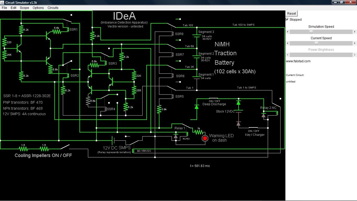
What the simulation does is this (and I hope the real circuit will do it too, one day...):
The key or charger turn on the stock 12VDC supply. This switches relay 2, turning on power to a SMPS (isolated) which then produces 12VDC with sufficient current to drive the cooling impellers and the rest of the IDeA system. (The relay shown as part of the SMPS is not really a relay - it's just there to represent the galvanic isolation by the SMPS because the applet has no SMPS to drop into the circuit!)
Once the SMPS is producing 12VDC, relay 1 provides relay 2 with 12VDC even if the key is turned off - but only if no imbalance is detected.
The IDeA comparethe the voltages of battery segments 1,2 and 3 to each other. If there is too much difference between these segment voltages, then the current fed to the opto-relays 1,2,3 and/or 4 will exceed 3mA and they turn on the (Darlington pair?) switch on the other side (inside of) the opto-relay, isolated from the HV battery side of the circuit. (The opto-relays are marked SSR 1-8.)
This switches relay 1 and lights the warning LED during riding or charging.
If the "Deep Discharge" switch is closed, then the circuit stays on after the key or charger is turned to OFF. The current drain will then continue until imbalance is detected; once this happens, everything gets turned off.
The circuit also allows to run the impellers at any time when the key is on (or the charger). So one can run the impellers continuously during riding!
The impellers can also run with the key (or charger) OFF, as long as the battery is balanced.
The current drain with impellers running should be around 0.5A to 0.75A, allowing to do a standing-still deep discharge to the point when the first cell reverses, then stop. If some sort of timer was connected at the "Deep discharge" switch, then after-riding cooling without complete deep discharge would also be an option.
With the shown resistor and transistor values, the maximum power at the resistors is about 420mW; the imbalance at 51V per segment triggers if one segment is at 50.71V or less; and the imbalance response is triggered at 34V per segment if one of them is at 33.58V or less. This allows for one segment at 34V, one at 33.59 and one at 33.17V to trigger the imbalance response.
I hope this makes some sense! It is all much easier to understand when the simulation is completely visible on the computer screen, because you can switch the switches on and off and change the battery segment voltages to see what happens.
Have you any access to a larger screen to look at it?
This information may be used entirely at your own risk.
There is always a way if there is no other way!
Hi Mik,
very impressive work! But there seems to be an error at relais ssr4. In the actual configuration it switches to nowhere even if the pack
is imbalanced because of highvoltage of Segment 1, so the IDeA whont turn off in this (possible) situation.
I´m not sure why you used relais in the "kernel"section of the circuit (because of the lack of optocopplers?)
As it gets rather complex I´ll make a first version of an IDeA only for riding aplication and with optocopplers,
which can drive a final relais or a schmitt trigger for a clear switching of the dashboard LED.
Greetings Mike
Thanks for spotting the error, I fixed it!
I used opto-relays because they seem to have a more "all-or-nothing" response than opto-couplers. But I'm not really sure about this!
Particularly the voltage rating of the ASSR-1228-302E of 60V could be a problem.
I'll make the circuit fit the simulation so that The Laird can have a play with it!
This information may be used entirely at your own risk.
There is always a way if there is no other way!
Here it is (I hope...):
The switches have been moved towards the left a little bit so that they will hopefully be accessible on most computer screens.
The relay 2 will not be visible, but it's open or closed state can be inferred by the current flow through the coil of the (virtual) relay in the SMPS.
Here is the code:
This information may be used entirely at your own risk.
There is always a way if there is no other way!
And here is the code for a similar simulation in which the SSR 5 to 8 have been removed and replaced with switches.
This is not a functional circuit, but it allows simulation of differential SSR closure times (and malfunctions).
I hope this helps to figure out the minimum voltage requirements for all the various components!
This information may be used entirely at your own risk.
There is always a way if there is no other way!
Here is the next addition to the circuit: A way to totally shut down the system to avoid the 7mA constant-on drain caused by the stock system.
It includes a "Hibernation / Hard Reset" switch, an inrush current limiter of 10 ohm, and a contactor to close once the ICL has finished charging up the system.
The relay labelled "SDC" (for Self-Dis-Charge) is not really a relay in the real system. It simply represents that the battery is connected to the system in such a way that about 7mA flow when everything is turned off. It also enables the system to awaken when the key is turned or the charger is plugged in.
In the shown circuit, these functions are disabled if the hibernation switch is turned off. Nothing will work and the 7mA current drain stops.
A better, more easily accessible location for the main fuse is also shown (just as a label above the wire, because there is no fuse symbol in this applet, yet).
This circuit simulation is intended for use after the more basic IDeA design has been understood. Try it first, because with 6 x 17 cell battery segments and more switches etc it becomes more confusing.
The setting for the simulation in the code below show a situation where a deep, automated discharge is running (by powering the cooling impellers) until a single cell reverses. You can simulate this by reducing the voltage of 17-cell segment 4 from 16.6V to 16.5V.
Once this imbalance occurs, everything including the 7mA current drain is turned off.
Of course, if the intention was hibernation for Winter or a too hot Summer, then the hibernation switch should be opened manually when the battery is at about 40% SOC. It could then stand unattended for more than half a year without likely problems when the scooter is eventually plugged in again!
And here the code for http://www.falstad.com/circuit/ (I hope the switches all end up on the visible part of the computer screen!):
This information may be used entirely at your own risk.
There is always a way if there is no other way!
Hi Mik, Vectrix should offer you a job at their "development" ;-)
By the way: If I remember the clock and "state of charge display" continue to work even if the battery is disconnected.
So the Mainboard of the V has a battery onboard like the motherboards of PC´s have? My question what happens if the bike
is in hibernation with disconnected main-battery. Will there be a moment where the onboardbattery is empty and what will
happen to the scooter if you try to bring it back (reconnect the mainbattery)? Maybe the Bike needs the mainbattery for
longer lasting?
Greetings Mike
I had the battery out of the Vectux during the M-BMS development for about 3 1/2 months - and it started up without a glitch!
Some of the cells that AZVectrix donated to me were charged to about 14Ah over 7 months ago and still have several Ah of usable charge in them now.
Some other AZVectrix cells were neglected by myself and left empty since I got them. I thought I had checked them all, but going through my records I found that I had put 5 cells aside because they had slight case deformities (probably from before the time they were filled with the actual battery material). I'm pretty certain they had been empty with about 1.2V open voltage. They now still have 1.08V to 1.15V open voltages.
I think that the self-discharge rate approaches zero when the SOC does the same. My guess is that the cells can be left for over a year without dropping their voltage too low for the stock charger to kick in - but only if the 7mA constant-on drain is removed. That drain would probably continue (maybe with weakening current?) until all cells are at zero volts - and reverse charge all cells except for the one cell with the highest capacity.
This information may be used entirely at your own risk.
There is always a way if there is no other way!
Hi Mik,
I did not mean the NIMH pack, I´m wondering how the systemclock/computer are powered when the NIMH pack is not conected. There must be a second small
battery like in normal PC´for the system clock. What happens if this battery is left without the mainpack often or for a long therm? My Scooter was
disassembled for 5 months, but only once. my question is raher: will the mmainsysem of the Vectrix be affected, if the NIMH pack is disconnected for
a long period and/or often?
Greetings Mike
Wow Mik,
I'm very impressed by your learning skills :-)
You're only using the applet for, say a week or 2? With no electronics background!?
Carry on, I'd say :-)
"doing nothin = doing nothing wrong" is invalid when the subject is environment
Pages