electric vespa

jstept's picture

The Rezistor - still works...

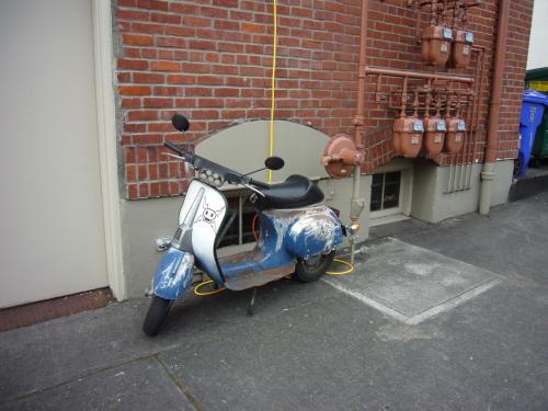
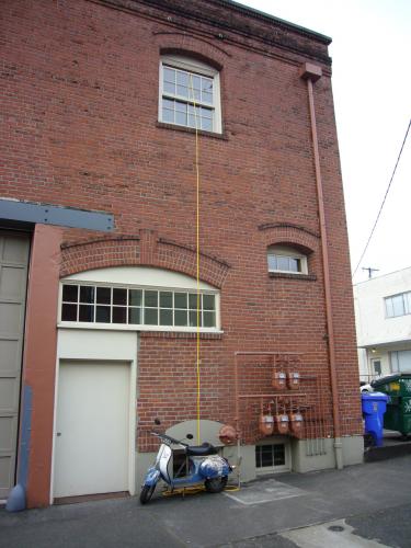
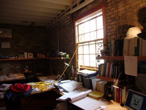
Rode the Rezistor to work yesterday and today. I haven't been able to find any electrical outlets on the outside of the (very old) building I work in, so I had to improvise.

workcharge_1.jpg
workcharge_2.jpg
workcharge_3.jpg

Not that this is absolutely necessary: my commute is 6 miles round trip, which is well within the Rezistor's range. I just wanted to see what I would have to do if I really needed to charge up at work for some reason.

I just started taking voltage readings before and after riding and charging. Right after a charge, the batteries read at 42V. After sitting overnight in the garage it drops to around 37V - might I have a slow charge leak somewhere in the system? Then after I ride it 3 miles to work it reads 36V. I'll continue to take readings, and I should really start to check the individual cell voltages to see how well Yesa's BMS is keeping the cells balanced. The BMS on one of the packs is rather inaccessible, unfortunately, so I'll have to take readings from one of them and assume they're both behaving the same way.

I've been swamped on a deadline at work, so I haven't had time to get the turn signals working or to build license plate illumination and reverse lights. I ordered some LED replacement bulbs for the rear signals (about $6 for the pair on ebay) and some blue electroluminescent wire that I plan to wrap around the motor power cables for ornamentation.

I've also started some research on what to do about the bodywork. If I go with the bare-metal look, there's a product called Gibbs penetrant/protectant that will prevent and supposedly even reverse corrosion. I found some pictures of a roadster restoration that was left in the bare-metal state using this product. I suspect you have to reapply it at regular intervals. There are some local powder-coating companies that will apparently do the sandblasting for you as well as the powder-coating; I might be able to get this done for less than $300. I plan to ask about the possibility of clear powder-coating, but I might just go for the brightest color I can find for safety reasons.

jstept's picture

The Rezistor - preparing for road tests

The replacement controller from Team Delta arrived on Wednesday. Fantastic service from Dan, considering I just explained the problem to him on Sunday. I installed it and, at first, got the same "MOSFET short circuit" error message from the controller as before. I wondered if the contactor might be faulty, so I took that out, fiddled with it as much as I could (which wasn't much) then reinstalled it. But then it occured to me that the 12V converter might be faulty, so I left that disconnected. That must have been it, because the scooter worked after that. Changing the controller setup from "speed" control to "torque" control did the trick.

But without the converter, I had no lights or horn. So on Thursday night I pulled out the converter and tested it. It was bad...somehow I had blown it out and it was creating a short-circuit between the negative battery terminal and the B+ connection on the Sevcon controller - hence the MOSFET short error message. So Sevcon has been vindicated; the controller was not bad after all.

Good thing I had the foresight to buy two converters - I installed the second one, this time with a fuse on the + input wire. Lights and horn were restored.

turn_signal_1.jpgturn_signal_2.jpg
Thursday night I also installed the turn signals I made (LEDs, acrylic, and 5-minute epoxy) and a couple of mirrors. Turn signals aren't working, though...I think the LED's aren't creating enough of a current draw to activate the flasher, or maybe I have something wired wrong.

DSCI0004.jpgDSCI0002.jpg
I made a little "REZISTOR" sign to fit in the horncast strip, and got my wife to paint the logo on the legshield. I was hoping to have it ready to ride on Friday night, where I could debut the scooter at the annual Spring Scoot scooter rally in Portland, put on by Twist'n'Play scooter club. The rally would basically serve as the initial road tests.

Results to follow shortly...

jstept's picture

The Rezistor - Final Assembly and Testing

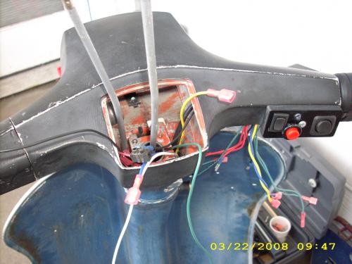
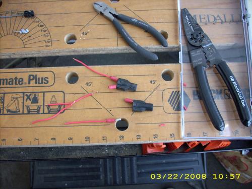
Well, it's been an exciting week. I spent much of last Saturday getting the brakes working, installing the levers, cables, and switches. The brakelight switches install in-line in the brake cables within the headset, so I had to figure out where to cut the cable housings to get them in the right spot.
headset_attachment.jpgbrake_switches.jpg
headset_wire_nest.jpgheadset_finished.jpg

Then I finished wiring the headset, making the connections to the switches, horn, headlight, brakelight, turn signal flasher, and reverse light. I also finished the controller wiring and put new leads on the keyswitch, the wires of which kept breaking off. I installed the horncast and the taillight and completed the wiring connections for those.
horn_installed.jpgiginition_key.jpg
taillight_installed.jpg

Last Sunday I started off by putting in one of the battery packs under the cowl. The BMS is just an exposed circuit board, so I wrapped it with a plastic bag and some tape to give it some nominal protection and weatherproofing. It's wedged in a small space on top of the battery so it's pretty well protected anyway. Getting the battery in was a tight fit.

I ziptied the two battery chargers into the underside of the seat. I plugged each one into an orange extension cord and then stuffed all the cords in there as well.
underseat.jpg

I bolted in the controller and by Sunday afternoon I was ready for a power check, using only one of the battery packs. I put the motor next to the scooter, connected the power cables, turned it on. I hear a click as the contactor engages, and my LED headlamp lights up, so that's a good sign. But I get the flashing LED on the controller indicating some error...oh, look, the control wires aren't connected to the motor. Plug it in and it works!
power_check.jpg

So then I had to move the thing off the back deck of my condo and into the garage for final assembly and a test run. Pushing it down the hallway and down a flight of stairs was a chore.
moving.jpg

On Sunday evening I put in the second battery pack, hooked up the motor, plugged in the battery leads, and was ready to test. I turned the key, engaged the forward switch, and slowly twisted the throttle. I could hear the motor and chain moving, but there was no forward motion. I looked down and could see the chain spinning around the sprocket, but the welds between the sprocket and main axle had broken.

So on Monday night I unbolted the swingarm assembly from the body, removed the rear wheel and brake plate, and took the swingarm and motor over to my friend Arden, who was able to fix it with his TIG welder on Tuesday. Tuesday night I picked it up and reinstalled it into the scooter. Thanks again, Arden!
chain_connection.jpg

Late Tuesday evening I tried another test run. This time as I turned the throttle I felt a slight tug backward and heard a "tink", then heard the motor spin some more while feeling no motion. This time, when I looked down, the chain wasn't moving with the motor, so something else had failed. I felt around the engine case for a bit and pulled this out.
broken_sprocket.jpg

The 11-tooth front sprocket had broken in half. The notch cut for the keyway had really weakened the sprocket hub, and it broke right along the keyway and one of the set screw holes. Also, it turns out I had wired my forward/reverse switch backward, although I swear that I had checked the switch polarity beforehand...oh well, at least it's an easy fix.

I went to McGuire Bearing on Thursday to see if they had a sprocket with a thicker hub, but all of their 11-tooth ones were basically identical, and they didn't have one in stock with 12 or 13 teeth. I called around and found a place that had both, and picked them up on Thursday. Both of them have much thicker hubs than the 11-tooth.

Friday night I put on the 12-tooth sprocket, only to find that my chain was no longer quite long enough. I made a chain that was two more links longer (you have to have an even number of links, of course), but then it was too long, and the chain rubbed on the engine case. I switched to the 13-tooth to see if that would take up the slack, but it still wasn't enough. This is frustrating. At least I got an opportunity to reverse the leads on the forward/reverse switch.

This morning (Saturday) I took the swingarm off and took it apart. I was able to elongate the motor mount holes slightly, but just enough to shorten the distance between the motor axle and shaft so I could fit on my original length of chain. This was a relief, since I had feared I might have to make extensive modifications to the swingarm. I reassembled everything and decided it was time for another test.

This time it worked. Sort of. I got forward motion, but if I accelerated too much the power cut out, including the headlight. If I reset the system by turning the key off and on again, I could again get forward motion, but it didn't last. I could get up to maybe 20 mph if I go really, really slow on the throttle, but then the power cuts out. Interestingly, reverse seemed to work a little better (and felt really weird) but again, the power cut out as I gained speed. I looked at the controller after the power losses, and saw the LED indicator blink 9 times. Sevcon's manual says this is a "rotor position sensor fault".

I suspect that Yesa's battery BMS is set to limit the current draw, and that this is causing the shutdown. Decibel1, another member of this forum, described a similar issue with his Yesa battery packs a few months ago, and I had kind of been expecting that this would also be the case with my battery packs. So I took the batteries out and disconnected and resoldered the leads on the the BMS so that it would be bypassed on discharge. Decibel1 seemed to get decent results with this approach.

I tried a few more test runs, but the behavior was about the same. I still get power loss after initial acceleration. Then after a few more resets, it stopped working altogether. I turn the keyswitch and no power gets to the headlamp, and the LED on the controller blinks 3 times. The manual says this means "MOSFET short circuit".

I poked around the wiring with my multimeter for a while, checking various connections and looking for a short, then noticed that I was getting a 40V potential between the positive battery lead and the scooter body. This seems wrong (and somehow unsafe), so I figure out that the exposed charger connector on the battery under the cowl is coming into contact with the body. I insulate that with some electrical tape, and the potential goes away. But I'm still getting the 3-blink message when I turn the key, and no power. I'm hoping I don't have to send the controller back to Team Delta for diagnostic and reprogramming.

jstept's picture

The Rezistor build continues

I haven't blogged in a while, but it's not because I haven't been making progress. It's just that when I get free time, I'd rather spend it building than typing and uploading photos. Here's a summary of what I've been doing:

battery_reconfig.jpg
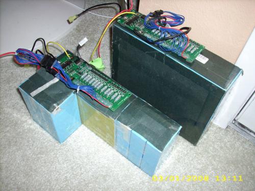
I had to reconfigure LiFeP04 battery pack 1 so it fit better in the space below the seat. This involved cutting the tape that held it together, cutting and resoldering some of the links between the cells, and extending some of the wires to the BMS.

rack1.jpgrack2.jpg
rack3.jpgrack4.jpg
I got some perforated angle, some hinges, and a bunch of nuts and bolts, and built a rack for battery pack 2 under the left cowl. Originally I was thinking this might have to be welded to the body, but I don't weld, so I ended up drilling some holes in the body. I don't think it looks too bad. It sticks out a bit underneath, but still looks better than an exhaust pipe.

taillight1.jpgtaillight2.jpg
taillight3.jpgtaillight_4.jpg
I took apart the taillight and replaced the tiny bulb (it didn't have a brakelight) with some LEDs mounted in a piece of acrylic. It screws in very nicely to the existing taillight mount. I wired a couple of resistors in series with a bypass so it functions as a brakelight as well.

contactor_in_place.jpgcontroller_rack.jpg
all_in_place.jpgsome_wiring.jpg
I figured out places to mount the main components. The main fuse holder, contactor, and 12V converter are screwed directly into holes I drilled in the body. I had a piece of angle left over from the B2 mounting, so I screwed that to the body where the fuel tank was, and I'll bolt the controller to that. B1 fits pretty well right in the space in front of that, and I don't think I'll need to build any special mount, maybe just a big rubber bungee to secure it to the angle.

horncast.jpg
The old horn runs on AC, so I bought a new DC horn from electricscooterparts.com (interestingly they are in Boulder Creek, CA, where my mom lives) as well as a keyswitch. The Chinese horn was much less expensive than a DC Vespa horn. I cut some notches around the edge of the horn so I could secure it into the horncast with screws. The previous owner gave me a new horncast along with the old one, so in the photo you can see the old on the left and new on the right.

The brake parts I ordered from Ptown Scooters finally came in this week, so I was really glad to get those. I'm reusing the original front and rear drum brakes, so I needed new cables and rear shoes. As I mentioned before, this scooter never had a brakelight (or turnsignals, or speedo...) so Steve at Ptown found me me some brakelight switches that install in-line with the cables, and I think these will work out nicely. Thanks, Steve!

center_stand.jpg
I got the missing bracket for the center stand, so I finally installed that. This makes work a little easier. I also got bolts for the seat attachment.

switch1.jpgswitch2.jpg
switch3.jpgswitch4.jpg
The old switchpanel was a mess, so I built a new one out of three layers of 1/8" black acrylic that I superglued together. The rectangular rocker switch on the left is for forward/reverse, the round rocker switch on the right is the turn signal, and the red button is the horn. The LED blinks red along with the turn signal. I bought the turn signal blinker at an auto parts store.

Most of the rest of the work is wiring. Today, using an unbent coat hanger, I pulled the rear brake cable through the wiring channel in the body, along with several wires for throttle control, forward/reverse, and lighting (including white LEDs for reverse, the housing for which I have yet to build). Pulling the wires was a total PITA; I'm really glad that's over.

20080110_first_sit.jpg
Yes, still ugly. And the Vespa doesn't look so great, either. I've realized at this point that this is really going to be two projects: the conversion and the restoration. I've never done a scooter restoration before, so I'm not really sure how far I'm going to carry it. I suppose it depends somewhat on how much fun it is to ride when I'm done.

Oh, and I got married. Huge thanks to my lovely wife for her continued patience and support as I finish the project!

jstept's picture

The Rezistor: got swingarm

V9A_case_split.jpgswingarm_wheel_side.jpg
I suppose I'm way overdue for an update, though there really hasn't been much progress until this weekend. The big development was the arrival of a V9A engine case from Sportique scooters in Colorado just before Thanksgiving. They found my WTB ad on scoot.net. It fits in the frame perfectly and the left side of it will serve nicely as the swingarm. I had to knock out the old rusty bearings and drill out a pin to remove the shifter assembly, but otherwise the aluminum case is clean and in good shape.

I almost ran into a snag with the brake plate (where the wheel hub bolts to the engine case). The V9A case has three studs that matches up with three holes in the brake plate. The brake and hub that came with the frame were actually from a PK series Vespa, and the holes in the brake plate were spaced slightly too far apart. Doh! Crossing my fingers, I paid a visit to Patrick at P-Town Scooters, one of our finest local shops, and he fixed me up with a brake plate and a 10" hub that fits the V9A case. Patrick also advised me to lubricate the crap out of the mainshaft bearings and chain, to the point where the lower portion of the engine case is basically a pool of oil. That sounds really messy, so I haven't completely accepted that proposition.

I purchased a new bearing for the mainshaft from McGuire Bearing, and also asked a fellow on their staff whether a fixed gear, belt, or chain would be the best option. He recommended a #35 chain over a belt, considering my speed and torque demands. They have an 11-tooth sprocket in stock that will fit right on the end of the Mars motor shaft. The driven sprocket will be a little more work; since the Vespa mainshaft narrows in the middle, where I'll be making the sprocket attachment, they'll need to modify a sprocket so that it can be split apart, then bolted back together to clamp onto the mainshaft. Pretty slick, but not cheap - he expected parts and labor to run about $60.

bolted-on_template.jpgnew_bearing.jpg

I took some plywood I had lying around and made a template for the plate that will serve as the motor mount. The nice folks at Parkrose Hardware cut a piece of 1/4" aluminum plate to the same shape, and I drilled some holes so I can bolt it to the swingarm and cut a big hole in it for the motor shaft. I stuck the swingarm into my oven at 200 degrees to let it heat up and expand, then gently tapped the new bearing in. The next steps will be tricky: getting the motor mount holes lined up properly, and slotting some of them just right so I have some adjustability in the chain tension. Then I have to line up the bearing for the other end of the mainshaft and figure out a way to secure it to the motor mount plate. Maybe a short chunk of aluminum pipe with I.D. to match the O.D. of my bearing? I have the plywood template to help me figure this out before I make too many mistakes with the aluminum plate.

swingarm_no_plate.jpgswingarm_with_plate.jpg

One other thing I learned: axle steel is really hard. I need to cut off the fat end of the axle, but my hacksaw barely scratched it. I may take it to a machine shop around the corner from my office and see if they can make the cut.

motor_mount_plate_bolted.jpgtemplate_with_motor.jpg

Syndicate content

Who's online

There are currently 2 users and 274 guests online.

Online users

WWWATTS.NET aggregates electric vehicle related blogs and podcasts

Support V is for Voltage