
Since I recently discovered the joys and delights of walking alongside the scooter for nearly a mile up a steep hill while returning home, I am wanting to fit an additional voltmeter to my VX-1 so that I can easily keep an eye on the battery voltage while the bike is being ridden without having to keep hitting the kill switch and pull the rear brake and then re-arming the controller etc.
I have decided that I need to have an LCD display so I can still see it in bright sunlight and this is what I've come up with so far: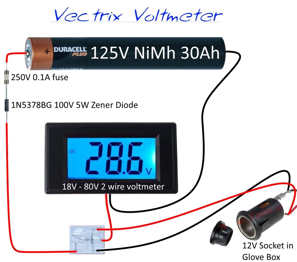
I am planning on using a simple two wire 18-80V panel meter and this was the highest voltage meter I could find that doesn't require a separate isolated power supply to make it work. By using the zener diode I am hoping that the display will work correctly (although it will obviously read 100V too low) and it should still just work even if the battery was as low as 118V. It should also indicate small voltage variations as it will increase and decrease by 0.1V instead of whole volt.
I am only really interested in seeing readings over 25V during use and up to about 50V while charging.
The display is nice and large and should hopefully be big enough for me to read with just a quick glance and it's also backlit for night-time use.
I am hoping that someone with better electrical knowledge than myself will be able to say whether the above circuit will actually work or not.
I have tested the 3.5-30V version of this gauge and it draws less than 8mA when connected to a 12V battery, so I'm hoping that the 18-80V meter will be well within the zener diode's 50mA rating. (5 Watts ÷ 100V = 50mA)
The relay is simply used to turn the meter on and off with both the ignition switch and the built in charger, but I might leave the gauge permanently connected and switch the backlight on and off wit the relay instead. Then I can quickly estimate the battery's capacity without having to turn the ignition on or switch the charger on.
If the meter draws less than 8mA with the backlight on it is unlikely to discharge the battery very much over a long period of time with the back light turned off.
So here are my questions and concerns:
- Will the above circuit actually work?
- Do I need to add fused protection on the 12V relay feed from the socket in the glove box?
- Have I overlooked any major safety issues?
- Am I right in assuming that the maximum voltage at the meter will only ever be 52V (and hopefully non-lethal)?
- Is there an easier or more suitable alternative?
- Does the 12V socket share a common ground connection with the battery pack or is it completely isolated?
I had also thought using one of these battery gauges with a suitable resistor in line:
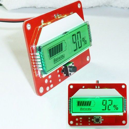
But it would need to be housed in a suitable waterproof housing and I'm not sure how I could effectively calibrate for the 125-150V range an the min and max readings on the gauge to properly relate.
Any suggestions, constructive criticism or comments will be genuinely appreciated.
Alan

Why not use a simple resistor voltage divider and drive a 2 volt meter to indicate 1/10 of the battery voltage, 142v = 1.42v
http://www.evalbum.com/preview.php?vid=1174
http://www.evalbum.com/preview.php?vid=4677
http://mhomoney.blogspot.com
http://Lithiumvectrix.blogspot.com
The 0-2V LCD meter is a 4 wire meter, so it would require a separate power supply of between 8 and 12V.
If I was going to use a separate isolated power supply for the meter I would probably use a 0-200V meter and put a high resistance in the high voltage battery supply to eliminate the possibility of potentially lethal current reaching the meter.
I also like the idea of being able to leave the display permanently on and just have the backlight come on with the ignition. This way I could easily check the voltage without needing either the ignition key or a mains socket.
If I was to use a 0-30V analogue meter and a 125V zener diode I could use it as a fuel gauge that would read from full to empty giving me a very rough indication of the available range in miles as the voltage tends to drop ~1 volt for every mile travelled on my typical trips (the battery is seven years old and I live in a very hilly area):
Although an analogue display would be fine while parked, I suspect the needle would vibrate all over the place while riding.
Alan
You could use a 9v battery as the supply, it would last a while on a LCD meter or get the 12 volts from the bike accessory circuit.
I suggested the voltage divider to keep the pack voltage away from the user.
Your zener circuit as drawn won't operate as drawn.
You need to reverse bias a zener to regulate voltage. A limiting resistor is needed and has to figure in the expected load.
http://www.evalbum.com/preview.php?vid=1174
http://www.evalbum.com/preview.php?vid=4677
http://mhomoney.blogspot.com
http://Lithiumvectrix.blogspot.com
Apart from the relay and fuse, the circuit I have drawn is basically the same as this one:

Admittedly, I have placed the resistance (the Voltmeter) on the negative side of the diode instead of the positive side, but I can't see how that would prevent the circuit from working.
The circuit diagram that you have posted is also similar to the one above, except yours has an additional output for plugging in an external load.
With the external load removed, the voltage measured across the zener diode (V out) should still be the same.
As I still can't see any obvious reason as to why my proposed circuit shouldn't work, I may have to get an assorted pack of zener diodes and try some experiments with some low voltage circuits first and try and find out how these zener diodes actually work.
Alan
Could you use a 2 resistor voltage divider circuit too?
Regards,
Peter
-----------------------------------------------------------
Central Scotland
Here's an update of my progress so far for anyone who's interested.
I have received the 18-80V voltmeter and ten of the 100V zener diodes. I purchased ten because it was only £3.28 for ten compared to £1.50 for a single one. I decided that it would be more difficult to loose or damage ten diodes compared to just one, and by having several to choose from I would stand a much better chance of finding one with a much closer tolerance.
I have taken some current measurements at different voltages to determine what the current drawn by the 18-80V 2 wire voltmeter will be at the voltages I will be measuring.
Fortunately it was well below the zener diode's 50mA power rating, but I was surprised to see such a large difference in the power consumption figures at different voltages both with and without the backlight LED connected:
At 21V, having the backlight turned on uses three times as much power as having it turned off, but at 50V it only increases the current being used by less than 15% when it's turned on.
As you can see from the above chart, the meter will only be drawing a maximum of 10mA at 50V (150V battery voltage less 100V zener diode).
I had also ordered a pack of assorted zener diodes from China at the same time as the voltmeter so I could try some experiments with lower voltages, but as they have not yet arrived, I couldn't resist playing with some larger voltages instead.
I hooked up some of my LiPo packs in series to produce a 26S pack and connected one of the zener diodes to the negative terminal. Using my multimeter I measured the voltage between each side of the zener diode and the battery positive terminal. I had a total pack voltage of just over 106V on one side of the diode and around 8V on the other. It seemed to be working as expected but I would need a higher voltage after the zener diode for the 18-80V meter to work.
So I added another couple of 4S packs to give 34 cells in series and the total pack voltage reading on my multimeter was exactly 140.0V before the zener diode and ~42V on the output side.
By this time I was convinced that the output voltage was low enough not to damage the 18-80V meter so I went ahead and connected it into the circuit.
When I first connected the pack the voltage reading started to slowly decrease but it eventually settled down to a steady reading after a being connected for about ten seconds or so.
I tried each of the zener diodes in turn to find the one with the best tolerance. The best one gave a steady reading of 40.2V which was a lot better than I had expected it would be.
I now need to decide where it is going to be be fitted and also whether it will be permanently connected with a switched backlight or whether I just switch the whole thing on and off with a relay as per my original diagram:
Although the residual current draw might only be between 2mA and 6mA between rides, I expect it could make a noticeable difference during the winter when the scooter is likely to remain unused for several months.
I could also use a manual switch fitted under the seat to simply isolate it during storage, but as I also intend to install a trickle charger controlled by a plug in timer unit, it shouldn't really matter.
Alan
I just installed a(CYCLE ANALYST FROM EBIKES.CA IN USA AND IT WILL REMOVE ALL YOUR PROBLEMS OF NOT KNOWING ANYTHING. ITS THE BEST THING FOR VECTRIX SCOOTERS. COOPER.
I Agree, buy a CA, install and enjoy. You'll find Consumed Ah pretty useful.
Thanks for the suggestion guys, I have several of the Turnigy Watt meters that I use on my other ebikes, and I must admit that I do find the consumed Ah function very useful, but these obviously won't handle the high voltage of the Vectrix.
Presumably you are both using the Cycle Analyst V2.3 High Current version with the 0.5 mOhm external shunt?
I can see that the Cycle Analyst Version 3 offers some very useful functions for standard ebikes, but I imagine the additional functions would probably be of little benefit on the Vectrix.
What switched supply do you use to power the Cycle Analyst so that it comes on with the "Ignition"?
Is it straightforward to tap into the hall sensor wire to read the wheel speed signal, and if so, how many pulses per revolution are produced, or do you simply not bother with the speed function?
Although the Cycle Analyst would be a very useful addition, I can't really justify $200 for a Cycle Analyst when replacement battery cells will be a much higher priority in the near future.
Perhaps I should put one on my Christmas list and see if Santa will visit me this year.
Alan
The (ca) has a red wire that hooks to main battery full voltage I just installed a on-off toggle switch in the dash to turn it on and off because it draws 10ma which when added to the bikes 7ma thats a lot. I installed a 200amp relay to shut all power off but I all so added a (125 volt----184 volt step down to 12 volts convertor and it puts out 35 amp @ 12volts. whichcan be used for any add-on's @ 12volt. PS the CA has a wire nad mag. for the speed-o.COOPER.
HI MR. "R" Thats the best CA support bracket that I have ever seen.
ThanKs, B,
Very easy to build, it is a flat stainless panel cut by laser. I designed the pattern in autocad, if you like it, I can send it to you, and have your support cut anywhere with laser equipment.;-)