
Building upon and continuing from this thread: http://visforvoltage.org/forum/9675-how-improve-nimh-vectrix-battery-it-becomes-damaged
Going back to the original suggestions for improvements:
A) Additional cooling and battery temperature equalisation, during charging and maybe also during riding and parking.
Solved - by the Lairds Charger Software modifications, keeping the cooling impellers running during riding, charging, and afterwards for an hour. Also solved by using an external 12V 5A power supply (ABCool).
B) A way to gently equalise the battery with minimal heating.
Solved - by the Freddy charger and diode protected connections to tab 1 and tab 103. Could also be done by connecting to the stock charger cable connection under the front fairing. Can be combined with use of the ABCool.
C) A way to fully discharge the battery to remove voltage depression and achieve full capacity and battery gauge synchronisation - without riding around in dangerous traffic like a lame duck!
Solved - by using the Lairds software, either keeping the MC and cooling impellers on as long as desired, or repeatedly running only the cooling impellers for 1hr at a time after turning the scooter off. See D) for when to stop discharge.
D) A way to detect cell reversal during discharge, for those times when the stock system misses it and damages the weakest cells. (It is now known that the stock "BMS" never detects any cell reversal.)
Solved - the Imbalance Detection Apparatus (IDeA). Split the 102 cell battery into three equal parts and compare the three voltages (through resistor protected cables). A voltage difference of about 1.2V between the three measurements indicates a cell reversal. The tricky part of how to automatically decide if (or if not) a cell reversal is occurring, and what actions to trigger as a result of the knowledge that a cell reversal is occurring, shall be dealt with by people smarter than me when they have time to fiddle with building a machine to do this. I will simply use three voltmeters and compare their readings by eyeballing them at times when imbalance is expected to be about to occur, and then do what needs to be done manually.
E) Logging of data to determine when an EQ charge or exercise cycling is needed - and to know when it is complete.
Not needed - or a logbook and a pen will do at a pinch. When range reduction, cell reversal or performance reduction occurs, look up how long it's been since the last EQ charge or exercise cycling, then try to do it just before it will be needed again next time.
F) Removal of the 7mA continuous current draw during storage.
Too hard basket for now. Can be solved by setting reminders to recharge on your calendar, or by connecting a weekly charger and The Lairds software so that a charge occurs for 30min each week throughout winter.
G) Placement of the fuse in a more accessible location.
Too hard basket and not needed if ICL is used and fuse upgraded to 200A.

The main new question to add to this list is this one:
H): How to fix the failure prone ESD charger before it suddenly lets the magic smoke out?
Because without the ESD charger, the Laird's software cannot help with solving problems A) and C) above.
Or:
I): How to replace the ESD charger with something more reliable, that can be programmed to charge similarly to The Lairds ESD charger algorithm?
This information may be used entirely at your own risk.
There is always a way if there is no other way!
If I could get hold of another new version board I know of a couple of people who are able to reverse engineer the daughter board used ont he new version that eliminates the constant power draw
If there is enough demand I could get some copper spacers made up that would allow the fuse to go on top of the battery - same as the official lithium conversions do it
having said that I have only heard of one 200A fuse blowing
Daily Ride:
2007 Vectrix, modified with 42 x Thundersky 60Ah in July 2010. Done 194'000km
Now about point D): Detecting cell reversal using the IDeA:
I found that some bright sparks have invented and built LED voltmeters that only require 2 cables to be connected. They are powered by the voltage source that they measure and they draw a maximum of 7mA current. When turned off (by a switch in the cables), they draw zero power.
They are also waterproof.
See this spec sheet for details and let me know if I'm barking up the wrong tree here (I hope not, because I've just ordered a few of them): http://www.murata-ps.com/data/meters/dmr20-10-dcm.pdf
I think they will fit on the side of the instrument panel above the glove box.
DVM1 will be connected to tabs 1 and 35; DVM2 to tabs 35 and 69; and DVM3 to tabs 69 and 103. That way, each DVM monitors 34 NiMH cells. All these tabs are accessible in the battery top layer without any need to take the battery apart or to remove it from the scooter to install them.
In order to prevent possible electrocution, the cables leaving the battery will need to be connected to the battery via resistors, so that the maximum current passing through them will be limited to safe levels. But enough current needs to get through to power the DVMs. That could be the tricky part...I'll experiment when the devices arrive.
This information may be used entirely at your own risk.
There is always a way if there is no other way!
I think we can strike this one from the "to do" list since:
a) It's now possible to "disconnect" the charger after the end of a night charge. It's important because it prevents the charger to be ON all night after the charge, getting very hot and pomoting the now famous ESD failures. So it will only be ON when it's charging. I have it in my bike.
and
b) ESD chargers can be fixed (some at least).
Like all products failure is still possible but this two steps give the Vectrix comunity hope.
All of this done by those portuguese comercial bastards called Fuel Free Motos. :D
I will do a disclaimer again. I'm nothing but a very happy costumer!
Cheers
Is the Runke charger an option? If so, then this is solved.
Those portuguese comercial bastards at Fuel Free Motos have haked the code for the Runke to.
Cheers
Unfortunately that did not save my ESD charger. I found the standby power consumption very early and then I almost always used a timer to disconnect the charger. I also received a replacement Vectrix a few months after this post http://visforvoltage.org/forum/2547-vectrix-reports#comment-12252 was written, so the charger that failed recently has seen very very little standby time, but it still failed at around 16000km after about 7 years.
This information may be used entirely at your own risk.
There is always a way if there is no other way!
I have started to run some tests with the 2-cable digital voltmeters (DVM) to determine if and how I can make this imbalance monitor electrically safe. With that I mean that it does not increase the risk for electrocution or injury after the scooter has been mangled in an accident.
To stay on the safe side, I assume that the bare copper ends of the cables will be poked through the skin into the body, with an internal body resistance of 500ohm. The resulting current needs to be as low as possible, preferably less than 20mA, but definitively below 100mA.
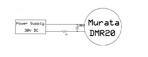
The problem that showed up is that the DVM appears to be drawing current in an intermittent fashion at some voltages. That's just my assumption though. What happens is that at 30VDC, with a 1kohm resistor in series, the DVM shows fluctuating voltage readings.
The voltage fluctuations are absent with larger value and higher value resistors in series as per the list below:
30V DC supplied by bench SMPS:
Resistor in series: Voltage displayed by DVM: Fluctuating or stable voltage display?
5ohm 29.9V stable
22ohm 29.8V stable
47ohm 29.7V stable
820ohm 27.0V stable
1000ohm 26.3V fluctuates
1500ohm 24.5V fluctuates
5600ohm 11.1V - 16.5V fluctuates wildly
10000ohm 5.3V display slightly dim stable
15000ohm 4.6V , dim display stable
22000ohm 4.2V , very dim display stable
33000ohm no display
Because measurement accuracy is not really required for battery voltages below 108V, the minimum voltage for each DVM will be 108V/3 = 34V. Therefore I measured at 34V and found that with a 1kohm resistor, the voltage display is just stable.
A 1kohm resistor is not quite enough for safety though, so I think I might have to add capacitors to stabilise the voltage at the DVM, and possibly diodes to stop the capacitors from discharging back into the cables.
See diagram below, please.
Will have to edit this post later, running out of time.
This information may be used entirely at your own risk.
There is always a way if there is no other way!
Well, this has me stumped so far....
Probably a typical rooky mistake, but I can not quite figure out why a electrolytic capacitor across the input of the DVM does not make a difference to the voltage fluctuations.
I tested the DVM from 0V to 36.7V DC without resistor in line, and no display voltage fluctuations occur at all.
But with a 1kohm resistor in series, the voltage display fluctuates if the input voltage is less than about 34V.
Measurement with another DMM shows that the voltage actually fluctuates, not just the displayed voltage.
Adding a 100uF capacitor, or even a group of 4 x 100uF capacitors across the DVM http://www.murata-ps.com/data/meters/dmr20-10-dcm.pdf input cables makes very little difference, except for during the short time when the capacitors are charging up. Once the capacitor is full after a few seconds, the voltage fluctuations resume with the same min/max values. The only difference I can spot is that the voltage jumps from 32.1V to 32.5V and back every 1/2 second or so, while without capacitors it jumps at about the same speed, but it jumps with smaller steps within the same min/max range: 32.1V - 32.4V - 32.5V - 32.1V - etc etc
Any ideas what is causing this and how it could be fixed, anyone?
This information may be used entirely at your own risk.
There is always a way if there is no other way!
Hello Mik
the point may be that your DVMs draw now their operating current about the in line resistors and draw that current not constantly.
I wouldn't work with this big capacitors at the input. If they work stable with a in line resistor in your table with about 800 Ohms, so why not ?
Another methode would be using a little galvanic isolated DC/DC converter (Traco etc.) to get the operating power for the DVMs and to use Standard DVMs which are not powered by input.
regards
Klaus