
Some Vectrix owners have now had their last battery replacement under warranty - and others must repair the battery themselves by replacing damaged cells - or find someone with the know-how to do it for them.
In any case, at this point it might be worth the effort of making some improvements that are likely to increase the chances for a very long battery life!
Particularly if the battery is already dismantled to cell level, one could more easily add some devices to improve battery management.
What are the options?
What is safe?
What is effective?
What has the best cost/benefit ratio?
What would be the optimum - regardless of additional cost?
CAUTION: These batteries are very dangerous! Do not do any work on them without the appropriate tools and training!
Hopefully we will be able to develop some recommendations here that could be handed to an EV workshop or electrician, so that they can build it for you if you do not have the skills to build it yourself.

A few starting points to get things going:
What I think is needed (in order of importance):
A) Additional cooling and battery temperature equalisation, during charging and maybe also during riding and parking.
B) A way to gently equalise the battery with minimal heating.
C) A way to fully discharge the battery to remove voltage depression and achieve full capacity and battery gauge synchronisation - without riding around in dangerous traffic like a lame duck!
D) A way to detect cell reversal during discharge, for those times when the stock system misses it and damages the weakest cells.
E) Logging of data to determine when an EQ charge or exercise cycling is needed - and to know when it is complete.
F) Removal of the 7mA continuous current draw during storage.
G) Placement of the fuse in a more accessible location.
This information may be used entirely at your own risk.
There is always a way if there is no other way!
Mik, you're the one.Thank you.
(I apologise for not having enough knowledge to help in this post.)
Hi, here are my thoughts:
A) Additional cooling and battery temperature equalisation, during charging and maybe also during riding and parking.
>> Using some precooling like Mik´s ABC would be great. As the fans are connected via plugs: What about an "interconector"
between fanplug and Vectrix plug, using a "relay-switch". If you want you can run the fans from a little battery, when
the Vectrix-mainboard decides to power up the fans the relay uses the power to disconect the battery and run the fans
directly via Vectrix-suply. I´m not sure if this is how the ABC runs right now? Sorry I dont´t have the time (men at work)
right now to draw a little shemata to show what I exactly mean. I will post it later.
B) A way to gently equalise the battery with minimal heating.
>> As you mentioned in another post a plug (waterproof and save) to connect a small charger like the "universal freddy".
C) A way to fully discharge the battery to remove voltage depression and achieve full capacity and battery gauge synchronisation - without riding around in dangerous traffic like a lame duck!
>> It´s tricky to discharge the pack without reversing the weak cells. As the battery is organised in 12 packs, what about a
discharge-wiring for each pack so you could control 8-9 cells per pack, which maybe isn´t so harmful when discharging to a
low level. This wiring could be used for an equalising process too.
D) A way to detect cell reversal during discharge, for those times when the stock system misses it and damages the weakest cells.
>> There would be 2 ways: Heat and/or voltage. I tested a little circuit (Mik maybe you remember when we discussed about the BMS
on www.vectrix-forum.de)with two spare cells. One full one half empty discharging via the CBA-unit. It worked ! When one cell
was depleted the voltage was low enough to activate the circuit to show it.
+ it is a small cheap circuit about 3 Euro.
+ if one of two cells is empty it can be shown via LED or accustic signal (with an optocoppler turned on by the circuit).
+ the circuit is small enough to mount it into the batterypack, so only the wiring for output is needet (when using an
optocoppler there would be less dangerous wiring outside the pack.
/ The circuit needs 2 cells to watch, otherwise the voltage is to low and the results are not very accurate.
- you need 102/2 !51! of these circuits a lot of soldering and work to connect to the battery.
- very small but permanent current draw from each circuit.
- If one of the circuits fail, the atached cells could be emptied causing an heavy unbalanced pack.
The resisors shown are for a 12v Battery some rework is needed here.

The second way to watch the cells and their temperature using thermal resistors as the stock bms. By puting the thermal
resistors in series for the cells of each block (8-9 cells). If one cell heats up dramatically (like many from us have
seen already - me to befor my batery was reworked/fixed)the thermal resistor will change its value a circuit managing the
block could give a signal.
+ no current draw
+ it would be possible to watch each cell similar to the circuits described above, or one pack (simpler/less work)
+ It could detect low level dischgsarging (heat) and overcharging (heat)
- I don´t know yet if it works puting 8-9 resistors in series? Maybe if all cells heat up to 30°C it has the same result
like just one resistor heating up to 45°C
- Maybe if a cell heats up enough to trigger the circuit, cell-reversal could already have damaged the cell.
E) Logging of data to determine when an EQ charge or exercise cycling is needed - and to know when it is complete.
>> something like the braindrain battery-monitor? but it would need a shunt.
F) Removal of the 7mA continuous current draw during storage.
>> dont´t laught I use a similar part in my Fiat Panda Electric:

It is a fuse and a switch in one combined. By opening the fusebox the fuse is pulled apart form the contacts. You don´t have
to touch te fuse to open the circuit, but when the box is completely open you can change the fuse without riscing a shock (the
fuse is disconnectet from any part with dangerous voltage. Of course dont put a pice of metal in the open box that could be
very harmful. Before closing the box you need to activate some kind of inrush current limiter.
+ save
+ the replacement fuses are cheap and easy to get (many sizes, my panda uses a box with two 160A fuses)
+ easy to open the circuit
/ would need a ICL Circuit activated by a switch before puting the Fuse back.
- for safty it still shoult be positioned in the battery container, but it would be a better place than on the mainboard.
G) Placement of the fuse in a more accessible location.
>> See F). Another possible place: the glove-box
+ easy to open
- needs a waterproof solution
- heavy changing of the power-wiring is needet, wiring must be protected from any damage.
I´m sorry for possible mis-spellings and gramaticaly errors in this post...
greetings Mike
I´ll add some shematas and drawings when i´v had time to make them...
and maybe correct the misspelling ;-)
That's how the ABCool works, except that the 12V DC from the ABCool overrides the 12V DC from the stock system. But It could be built to work either way. Details can be found here: http://visforvoltage.org/forum/7471-abcool-40-vectrix-auxiliary-battery-cooling-system

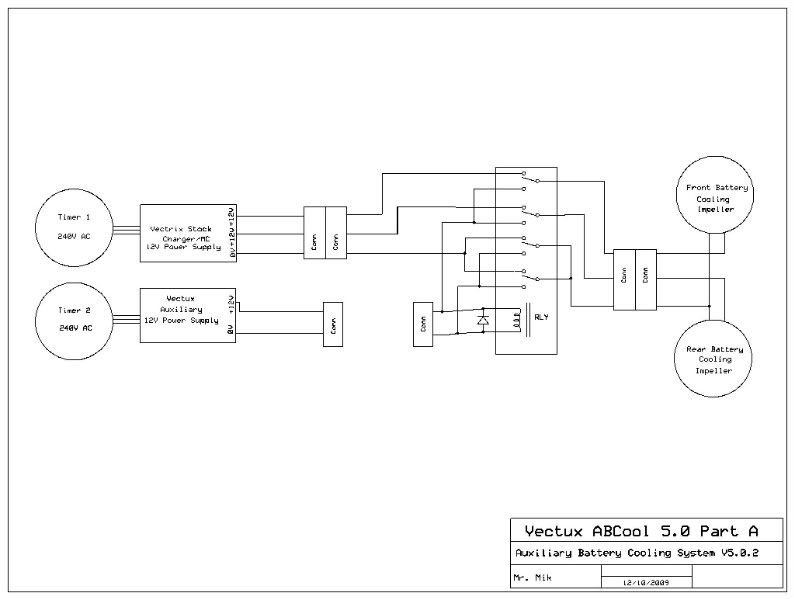
The gap between the connectors can be closed either by plugging them together, or by plugging in a 12V battery for cooling away from the grid.
If no other modifications are wanted, then something like an ABCool would be the easiest and most effective method of adding life to the battery, particularly in hot climates. With the two timers of the ABCool, you can set cooling to commence at 0200am, charging from 0400am to 0530am, cooling until 0700am; then start the day with a cool, 80% charged battery.
Then, plug in an auxiliary 12V battery (or grid) to run the impellers all day if the VX-1 is parked in the sun at work or wherever. It will keep all cells at an even temperature. If it's a hot day, all cells might get 40degC warm - but without it the top cells might be over 55degC and the bottom cells still around 40degC. (Best to keep it out of the sun, though!)
It is also totally reversible and requires no opening of the battery box and no access to any dangerous voltage parts!
.
.
The ABCool has performed beautifully for years and I consider it proven, safe and reliable - but I want more than that now! I hope to find a way to integrate the auxiliary cooling with the part C), the "deep discharge / exercise cycling" out of traffic.
.
.
Some 12V DC switch-mode power supplies (SMPS) might just be perfect to be powered by the (1.1V x 102 cells = ) 112V to 153V DC from the main battery.
Many of them can be powered by DC voltage - the big question is if they can go low enough to allow a deep enough discharge. I don't think less than 1.1V per cell is needed, because the 50W for the impellers, assuming 80% efficiency, would cause about a 0.55A draw when the battery is at 112V. At such a low current draw, 1.1V per cell is deeply discharged. Even 1.2V per cell might be sufficiently deep, I'm not sure about the exact details.
For this purpose, a SMPS could be installed inside the battery compartment, permanently connected to the battery positive and negative terminals. The 12V DC output would be the only part leaving the safety container. If the 12V output of the SMPS is fully isolated (floating), then it should be completely safe to run the 12V cable to accessible parts of the scooter and connect switches to it. It can then power the impellers during riding and parking, power additional control electronics and discharge the battery deeply simply by running the built-in impellers!
Running the battery down to about 20% SOC (=6Ah remaining) would give a fair safety margin to avoid reversal of weaker cells - and allow complete discharge of the battery overnight by running the impellers for 12hrs. The built-in 12V SMPS would also power some control circuit which detects the voltage pre-reversal of a single cell and automatically terminates the deep discharge. At that point the battery will be as empty as you can get it without damage to any cells. Initially, I'd want it to just stop there, until I have checked that it really worked as planned. Data logging would be great for that!
Then, when I have verified that the deep discharge has worked as planned, start the charger up. This could of course be done fully automatic once it has been thoroughly tested.
.
.
"The Laird" has already sent me a circuit design that can detect a 1V drop and switch something on or off as a result. The circuit will definitively need testing and tweaking - once we have worked out how long it takes for the first cell to go over the knee in the discharge curve and drop to zero V under the 0.55A load of the SMPS. It might take 30s, it might take 2-3minutes; the exact timing needs to be determined experimentally. I need to convert the diagram to some format that I can show on the forum.
.
.
Here is a preliminary list of requirements for the 12V SMPS to be suitable for the job:
1) Continuous 5A DC at 12V DC without over-heating. It might be possible to mount it somewhere in the cooling air stream.
2) Isolated 12V output - essential! How do you test this?
3) Ability to be powered by 110V DC to 160V DC (approx).
4) Low standby current drain. This would not matter much if a battery disconnect is also installed.
5) Small enough to fit somewhere into the battery compartment.
6) Tough - the vibrations of on-road use are quite severe.
I'm sure there are other requirements.
This information may be used entirely at your own risk.
There is always a way if there is no other way!
Hi,
to discharge the battery via an onboard DC-DC device sounds great. What about this company: Deutronic.
Might not be cheap but good quality and hits the requirements.
greetings Mike
Another question:
would it help to rearange the positions of the temp-sensors? They are always in the midle of the pack.
So the cells far away may heat up very much before a sensor may detect it: [0=cell, x=cell with sensor]
front pack rear pack /all layers as seen above
000x0000 0000x0000
000x0000 0000x0000
would this or a similar configuration help?: Putting the sensors away from the middle changing the
configuration a bit. as the sensors "feel" the temperature not only from the attached cell only, but
maybe from the cells around, this configuration might help to watch temp-rising faster and better.
It would need some soldering to get the sensorwires to the correct lenght and therefore battery
rework, but for those who have the skills / resources to maintain their batteries...
front pack rear pack / bottom
00x00000 00x000000
00000x00 000000x00
front pack rear pack / mid
00000x00 000000x00
00x00000 00x000000
front pack rear pack / up
00x00000 00x000000
00000x00 000000x00
@Mik maybe you postet something simmilar already, I´m not sure right now.
Greetings Mike
Yes, indeed, the DVC75-80-12 72/80/96/110VDC (56-154VDC) 12,5VDC 6A seems to fit the description. Great find!
http://deutronic.com/fahrzeugwandler/75-watt-pot-getr_data_en.pdf
This information may be used entirely at your own risk.
There is always a way if there is no other way!
Interesting idea, but I just don't know if the middle position is not really the best possible position already.
For a very thorough solution, one could use PTC strips like in the NHW10 Prius and Honda Civic / Insight hybrids. These monitor EVERY SINGLE CELL for over temperature! Maybe they have the right length and spacing to be used to make up an equivalent system for the VX-1 battery! Many damaged 6-cell sticks are available. It might be possible to get a good price (and cheap postage) for just the temp sensor strips from discarded Insight batteries.
One challenge would be to attach the sensors securely and tightly to each individual cell. And one would have to build a little electronic circuit to measure the resistance and take some sort of action if it rises too far (like stopping the charger and running the impellers).
If applied to each of the 102 cells, the resistance of the entire PTC strip would be about 17 ohm at room temperature. It would rise to several kohm if just one cell gets to 75degC. Easy to measure!
That modification would probably fall into the "over the top" category.
See this for more info on the PTC strips: https://www.endless-sphere.com/forums/viewtopic.php?f=14&t=12764#p189795
This information may be used entirely at your own risk.
There is always a way if there is no other way!
I got a quote for AU$162.96 (including shipping) for one of them. Seems quite reasonable, considering the quality. I think I'll buy one.
On another topic: What does everyone think about the PakTrakr and the Cycle Analyst as an additional gizmo for the Vectrix?
Maybe both?
This information may be used entirely at your own risk.
There is always a way if there is no other way!
My Paktrakr is quite old now, however, my one draws the power for its internal processor off the first few cells in the pack.
It used to pull my Emax lithium pack out of balance faster than my BMS could keep up with it.
If you are going to get one, ask if that design flaw has been rectified.
if not, get the one designed for 6v batteries, and use a SMPS instead of the first battery to get around the issue.
otherwise it is a good product.
cycle analyst is a very good idea (I put one on *every* EV I touch).
Matt
Daily Ride:
2007 Vectrix, modified with 42 x Thundersky 60Ah in July 2010. Done 194'000km
I send a question to the PakTrakr staff about this, will see what they have say about this unbalanced power draw problem. Another problem is the serial interface for laptop logging. One can use a serial to USB cable, I guess, but would it be possible to get a device that autonomously logs serial data for weeks or months at a time? The CSV data could then be run through a spreadsheet program to clearly show any deterioration in the monitored modules. Any reverse charging events should stick out like sore thumbs that way! But it needs to be a "plug and forget" solution, not one where you need to carry a running laptop all the time.
http://www.paktrakr.com/FAQ.html
With the Paktrakr 600 and one extra remote one could monitor all 12 modules. The hall current sensor might also be worth a thought, particularly if no CycleAnalyst is used.
Regarding the DVC75-80-12 72/80/96/110VDC (56-154VDC) 12,5VDC 6A power supply: Unfortunately they made a mistake and quoted AU$ where it should have been Euro! The AU$ price might be around AU$ 225.- at present exchange rates.
This information may be used entirely at your own risk.
There is always a way if there is no other way!
the paktrakr doesn't count Ah, so it will only show A.
but if you are data logging, you can integrate later for Ah for number crunching purposes.
one other thing I remember is there was lotsa noise in the data output, as the signal lines between the masters and slaves weren't that well shielded.
my emax put up alotta flak EMI wise, however, the Vectrix may not.
more stuff to try :)
Matt
Daily Ride:
2007 Vectrix, modified with 42 x Thundersky 60Ah in July 2010. Done 194'000km
I'm not sure to understand, but with something like a Logomatic v2 Serial SD Datalogger you have all the info recorded inside a portable SD card:
http://www.sparkfun.com/commerce/product_info.php?products_id=8627
The web says the firmware can be customized, do you think it can be adapted to read these kind of data?
The Paktrakr:
Ok.. Let's imagines there is a cell unbalanced. The Paktrakr succesfully detects the problem. But how can we get that (common) issue solved? what kind of BMS for NIMH or device should we use (assuming that we cannot replace the cell)?
overcharge at 3A......
Matt
Daily Ride:
2007 Vectrix, modified with 42 x Thundersky 60Ah in July 2010. Done 194'000km
Seems like they have neither fixed the design flaw, nor understood it's seriousness!
Below is my reply to the PakTrakr staff reply to my qquestion:
This information may be used entirely at your own risk.
There is always a way if there is no other way!
Ken Hall is more experienced with working with big 225Ah flooded lead acid batteries, where small amounts lost aren't significant.
nothing like trying to see if there are any work arounds with the hardware in front of you.
I still have my Paktrakr, ill lend it to you. (shame, I only just sent the battery off, could've saved on shipping :( )
I don't really want to be posting the schematics all over online per se as its probably Ken's livelihood here.
Matt
Daily Ride:
2007 Vectrix, modified with 42 x Thundersky 60Ah in July 2010. Done 194'000km
Hi, maybe somehow offtopic: An engineer in Tirol/Ausria made a Solartrailer for his Vectrix.

Not enough as rangeextender during a ride but he is able to recharge anywhere the sun shines.
Spreading the solarpanels, the trailer puts about 420w back in to the battery. I´ll try to
contact this guy, maybe some good input for this thread.
greetings Mike
Maybe an trailer would be an option, for short trips it is left at home, for longer trips you take it. Maybee some stuff like this:

source: Single Wheeler by www.freewheel.de
or an old Pav 40 or Pav 41 trailer. It seems a kind of replika is produced now in Canada or the USA (can´t find the Link yet)
Yes, solar panels are definitively on my "Want to do this" list!
I have even bought 320 small solar cells (waiting to be soldered together).
At this stage I do not want a solar charger, but rather just a self-discharge-preventer. Something to replace the 7mA system drain and a little extra to stop self-discharge.
This information may be used entirely at your own risk.
There is always a way if there is no other way!
wow thats a big boxy trailer.....I could fit 160, maybe 200Ah in there......
Daily Ride:
2007 Vectrix, modified with 42 x Thundersky 60Ah in July 2010. Done 194'000km
Hi,
How good a job does the latest firmware do? A local dealer (who has a vested interest in the problems being solved) told me he hasn't had anyone with the latest firmware have any problems with their packs.
Also Andy said:
http://visforvoltage.org/forum/9657-new-2007-vectrix-wwarranty-3200-usd-good-deal#comment-53377
I think the biggest problem when charging and in use is probably cells being different temperatures and even worse some cells being too hot. If the temperatures vary the charging/discharging will probably be inconsistent at best and if any cells are too hot damage some cells.
Mik, how do you charge to 80%? It might be that at 80% the charger doesn't use temperature to terminate the charge (thereby bypassing some potential problems (it would still be best to start with all cells at the same temperature but if the charger isn't using temperature rise to terminate the charge the problem of some cells temperature rising more than others should be minimized or avoided).
Will ABCool keep the cell temperatures from getting too hot and keep them equal or close to equal? If so running it before charging and while running and immediately after running (I think thats as important as during charging) should avoid most of the problems.
To fully discharge the battery can you turn on the lights or plug a load into the cigarette lighter to discharge the pack? Will that suffice for equalization?
How hard will it be to find the source of the 7mA continuous current drain and install a small switch as opposed to switching off the entire battery?
For controlling temperature before and after charging I'd consider a large fan, or swamp cooler or small AC unit on a timer. Maybe put the Vectrix in a tunnel-like box or insulated box for AC. Should be simpler than mucking with the Scooter. Might not be as effective for temperature equalization as ABCool if some cells start hot, but if thats the case using external cooling and ABCool might be best.
IMO for major pack problems the best solution will be to replace the pack with Lithium Cells and a good BMS, use an external charger and use a CA for keeping track the remaining energy while riding.
Thanks!
Mitch
Best Wishes!
Mitch
My new battery, after 4700km ridden with it, is as good as new.
My first battery was killed by the previous software. When I got the new battery, I also got the new software, so I'm riding the new battery with the new software from the beginning of it's life.
I also follow The Laird's advices found here: http://visforvoltage.org/forum/7912-nimh-battery-problems-and-cures
Mik, when did The Laird's thread disappear from the Handbook - Battery topics?
Keeping the sun of the battery cover is the most important part (at least in Australia). Otherwise you might get a 10-20degc temperature gradient through the battery in a couple of hours. I'm planning to apply heat reflective paint to the step-through cover.
Running the stock cooling impellers will eventually equalise the cell temperatures, but initially it cools the typically already cooler bottom layers of the battery more than the middle and top layers - but those are the ones that usually need cooling most! The ABCool simply powers the stock impellers while allowing complete control of timing by the rider.
At 80% SOC (as guesstimated by yours truly using Pi x thumb rules), the charger stops because the timer that I set manually before each charge cuts the power! Simple! I don't care too much if it is 75% or 85%, just around 80% will do for a long battery life. I generally let it charge (always in CP mode) for 12 minutes for every bar out of the 17 on the gauge that I want to replace. If I get it wrong, the high-voltage cutoff safety mechanism will kick in and stop charging at about 151V.
As mentioned above, the ABCool simply powers the stock battery cooling impellers from an external 12V source and disconnects the stock 12V impeller power whenever the ABCool is powered up. I run it a lot (all day at work where the Vectux is now unfortunately parked in full sun) and it does indeed avoid most of the problems. I hope that my wild guess is right that these impellers will happily run for 10 years cumulatively.....
Leaving the lights on will drain at least 6 times the maximum energy that can be sucked from the 12V supply in the glove box. I might be wrong about this.
For either the 12V auxiliary supply or the lights to work, you would need to leave the key in the bike - not such a good idea in most places! It would also take too long due to the low-ish current draw.
Running the stock impellers to drain the battery seems much more sensible - it would ensure that the cells are all at the same temperature (ambient temperature) by the time that the charge (likely including an EQ charge) begins.
IIRC someone mentioned that later VX-1s have a daughter-board installed in the top starboard corner of the motor controller - for this purpose! How hard it is to do, what is on the board etc is completely beyond my current understanding - a chunky contactor (with pre-charge resistor circuit) is not!
I'm hoping someone will take photos and measurements of the daughter-board one day and post them.
ABCool depends entirely on the ambient air temperature, just like the stock cooling system (it is the stock cooling system, powered at will). If your Vectrix is hot, it's much better to charge or ABCool it in a cool location or at a cooler time. Therefore, I set the ABCool to run several hours in the early morning before starting charging. Running the impellers from 0200am to 0600am will cool the battery in heat wave conditions - with or without concurrent charging!
That might be right and remains to be seen. Several people have put lithium packs into their VX-1s.
I still hope to get a good NiMH pack and then try to find out how long it can last with very good management. It may well beat any of the currently available Lithium packs as far as total distance travelled goes!
This information may be used entirely at your own risk.
There is always a way if there is no other way!
My new battery, after 4700km ridden with it, is as good as new.
My first battery was killed by the previous software. When I got the new battery, I also got the new software, so I'm riding the new battery with the new software from the beginning of it's life.
I also follow The Laird's advices found here: http://visforvoltage.org/forum/7912-nimh-battery-problems-and-cures
Mik, when did The Laird's thread disappear from the Handbook - Battery topics?
It never disappeared, it's just becoming hard to see the forest because of all those trees! I guess this is the thread you mean: http://visforvoltage.org/forum/7912-nimh-battery-problems-and-cures
On the topic of your battery: You are an "outlier" in almost every respect. If your battery does not last, none will! Even with a broken impeller it took months to bite the dust.
The reasons:
You live in a totally flat valley and generally stay away from the surrounding mountains.
You never accelerate hard.
You never ride above 70km/h.
Your (deep) garage is the same temperature all year round, about 16degC IIRC, just perfect....
You installed a charge point in this constant temperature garage.
You are experienced with batteries from you helicopter flying hobby and treat the battery as gently as generally possible.
These conditions are impossible to achieve for almost all other Vectrix riders - or undesirable, like avoiding hard acceleration.
You cannot generalise from such an extreme approach as your own!
This information may be used entirely at your own risk.
There is always a way if there is no other way!
I agree.
Hi Mik,
Thanks for your replies!
One way would be to use one or more of these RC chargers (NOTE: If you stay on the page a while you will get a discount pop-up for $122):
http://www.hobbycity.com/hobbycity/store/uh_viewItem.asp?idProduct=6609&Product_Name=iCharger_1010B+_300W_10s_Balance/Charger
You'd need six unless you want to do it all with one charger.
http://www.amainhobbies.com/product_info.php/cPath/1574_116/products_id/34714/n/ProTek-R-C-iCharger-1010B-Lilo-LiPo-Life-NiMH-Ni...
There are other RC Chargers that work with NiMH but someone posted that the iChargers are isolated. So if you wired the connectors you could charge/discharge the entire series pack with several chargers at the same time. I think it would be best to connect each charger to 2 adjacent subpacks.
How about a space blanket, reflective side out draped over the Vectrix, with some space for air flow?:
http://www.rei.com/product/407106?preferredSku=4071060000&cm_mmc=cse_froogle-_-datafeed-_-product-_-4071060000&mr:trackingCode=1...
Best Wishes!
Mitch
I want a way to EQ charge the entire battery safely and easily, with minimal fuss and absolutely no dismantling once the system has been installed.
A "Freddy" charger will do this nicely, the only question is how to best integrate it into the system. What cables, what fuses, diodes or not etc.
But definitively a charger that does the whole battery at once.
RE: the space blanket: Been there, done that. I inserted a high-tech building insulation sarking, comprised of tough bubble-wrap between two layers of what looks like gold and aluminium, between the impeller housing and the step-through cover. But I removed it again because the surface is so electrically conductive that it is just too scary to have on an EV.
This information may be used entirely at your own risk.
There is always a way if there is no other way!
I now have a used (but hopefully good quality) Vectrix NiMH battery - and spare cells to patch up any weak cells in the pack if needed.
Time to get serious about this project!
The new pack will initially be tested for capacity and self-discharge rate.
The next step will be to find a good solution to exercise cycling ("deep discharging") the pack without riding it. The DVC75-80-12 72/80/96/110VDC (56-154VDC) 12,5VDC 6A http://deutronic.com/fahrzeugwandler/75-watt-pot-getr_data_en.pdf is a bit expensive, latest quote: AU272.- or thereabouts. For that price I will first try other options - like using the 12V SMPS's which I have already lying around.
With the pack in the workshop I'll measure current draw by the SMPS under no load and while it is powering the stock impellers of the Vectux. The other important value to determine is the cut-off voltage at which the SMPS stops working - and any residual current draw once it's low-voltage cutoff has kicked in. Maybe I will power a main-battery-disconnect-contactor by the 12V SMPS, so that all current draw is terminated once the SMPS stops producing 12V. Otherwise the risk of discharging the battery too deeply would be great, even if only the 7mA constant power drain from the MC continued after deep discharge is complete. Then I will have to build a device that will automatically stop the discharge if/when the first cell drops to zero volt before the SMPS low voltage cutoff is reached. This device will not really detect the voltage of each individual cell in the 102s battery, but I think it can do the job anyway...lets call it the Imbalance Detector Apparatus (IDeA) for now.
The "IDeA" might have at least 2 separate functions:
1) Warning the rider of battery imbalance when the stock system is unaware of this, by illuminating a warning light but not cutting power. The rider will have the choice to continue to use all power that the stock system provides, but at the expense of the reversing cell; this keeps the vehicle roadworthy for longer in case it occurs in traffic.
2) Automatically cut power during automated deep discharges when imbalance is detected.
I think it might be quite straight-forward to design and build the IDeA: All that is needed is a voltage comparator that compares equal parts of the battery to each other. For this particular 102s battery the options are 102/2=51, 102/3=34 and 102/6=17.
I think the 34 cell option is best, because it would allow installation of the IDeA without taking the batteries out of the VX-1! All that is needed is installation of two tab wires between cell 34/35 and cells 68/69. These Inter-Cell-Connectors (ICLs) are accessible in the top layer of the front battery. An added advantage is that 7 out of the 8 cells on top of each side of the front battery are included into one of the three segments. These 7 cells are the cells most exposed to heating from the sun and most likely going to end up self-discharged ahead of the rest of the pack.
I have not done the maths on it properly, but I am convinced that it would be very unlikely that equal numbers of reversing cells would occur in all three of these 34-cell battery segments at the same time (this would make the cell reversal invisible to the IDeA). If there were only two battery parts to compare, then a single reversing cell in each half would not be all that unlikely. If you compared 6 parts, then you have to install wires into the deeper layers of the battery, which is difficult.
The IDeA needs to compare the three battery segments to each other and trigger the "Imbalance" response if a voltage difference of maybe 0.8V is detected between any two of them. At 1.2V x 34 cells = 40.8V per segment that should be quite simple!
The IDeA should run on the same 12V DC as the cooling impellers and the proposed contactor.
The IDeAs output must be galvanically isolated from the battery to keep everything as safe as possible.
Any suggestions or comments on how to do this would be most welcome!
This information may be used entirely at your own risk.
There is always a way if there is no other way!
Hi Mik,
quite good idea, but I´m afraid if it will work in a correct way. You would need 102 cells with nearly
identical capacity AND internal resistance. Otherwise the system might set "false alarms" when the cells
are under load... An other problem could be the temp-gradient of the twelve modules. As they are in 3
layers the bottom modules get the cool air heating it up, second layer gets heated up air heating it up
too, the third layer gets warm cooling air and/or is heated up by sun radiation. This temp. gradient might
be enough to differ the voltage as two the three packs have more 3rdlayer cells...
More work but maybe more useful could be a setup where each of the 12 modules is checked, if the voltage
drops to a preset value a signal is switched on. Advantage if all 12 signals switch on the pack is empty,
if only one or two modules send a signal they may be maintained in near future...
Source: evconvert.com
Greetings Mike
Pages