Notes on the Vectrix Battery – (Use, Improvements and Charging)
The NiMH battery chemistry is a topic which, for most of us, is shrouded in mystery. Myths seem to form a large part of what this chemistry is about and how it should be treated or not treated as the case may be.
The following script lists and explains a number of items which have been fished out of the muddy waters surounding the use and maintenance of NiMH batteries and particularly the battery used in the Vectrix VX1 Maxi-scooter.
First of all, some observations made whilst investigating the Vectrix battery application.
The 'New' Battery as supplied by G.P. Batteries
The battery as supplied by G.P. Batteries of Hong Kong to Vectrix, consists of 102 cells of (nominally) 1.2 volts per cell providing a total voltage, when charged, of about 138 volts (1.35 Volts per cell).
The cells have been selectively matched for capacity, open circuit voltage and internal resistance before being built up into the pair of batteries (front battery of 48 cells and the rear battery of 54 cells)
The batteries were supplied to Vectrix as paired, matched batteries with a long life expectancy.
There will, of course, always be minor variations in the individual cells because, no matter how close the tolerances are in manufacture, there will always be some difference between the specific characteristics of the individual cells. Also, the internal resistance of each cell increases with ageing and cell 'ageing' can itself be increased through miss-use, resulting in some cells of a battery ageing more quickly than others.
If this characteristic of the battery is not catered for in the design of the charge / discharge system, the inevitable result will be battery failures.
The Vectrix Design
Vectrix were in total control of the design of the scooter in terms of the mechanical, electronic and electrical side of things. Unfortunately, there have proved to be some deficiencies in the design of the electronics which have resulted in some problems with the batteries. Some of these problems have now been overcome, some are still to be dealt with. The problems are listed below along with some possible remedial actions.
The main problems experienced by owners of the Vectrix VX1 have been connected with the power source i.e. the battery and it's performance. Basically, complaints have been about poor range (Low mileage), blown fuses, failures of the battery cooling impellers, battery overheating, during riding and whilst on charge, the appearance of the 'red' battery indicator (low battery Voltage) and the BATHOT (battery hot) symbol and occasionally the BUSULT (Battery under safe Voltage) warning.
All of the above has been investigated and the following script contains the findings of that investigation.
Uneven individual cell heating and Battery overheating.
It has been noted that under conditions of high power discharge (hard riding / hill climbing) some of the cells within the battery suffer a greater heating effect than others.
It has also been noted that, on long hill descents, regenerative braking also results in the heating of some cells more than others (and all cells when the battery is near to 'full').
This has the effect that those cells which are hotter suffer from greater internal losses than the cooler cells and this in turn creates an imbalance in the individual cell charges i.e. some cells have more or less ampere hours stored than others.
The 'knock on' effect of the above is that the situation just gets worse and the cells become further imbalanced over time. This imbalance, if allowed to get out of hand, results eventually in low range and/or the appearance of various warning symbols and, at worst, a damaged battery.
The reasons for these heating effects
The basic reason that the cells heat up in use is because each cell has a voltage, a capacity and an internal resistance. The voltage and capacity are both of great value to us but the resistance is the unwanted feature of all batteries.
The resistance of a battery limits the current that can be drawn from the battery. When the voltage at the terminals drops due to the current being drawn, you are seeing the effect of the battery's resistance. The higher this resistance the less current can be drawn for a given voltage drop.
When current is passed through a resistance heat is generated. This heat can be measured or calculated. The heat in watts is equal to IxIxR (the current squared, multiplied by the resistance). In the Vectrix battery the cell resistance is quoted at 'less than 1.2 milli ohms' i.e.0.001 ohms.
If we assume that the actual figure is 1.0 milli ohms then when 100 amperes is drawn from the battery the internal heating effect will be '100 x 100 x 0.001' = 10 watts per cell or 1020watts (1.02 kWatts) for the whole battery. This is a considerable amount of heat and it all has to go somewhere.
Heat effect whilst riding
On a single ride using the 'full' battery capacity (say 24 Amp Hours) at an average speed of 40 MPH, the Vectrix draws (on average) 25 Amps giving a range of just under 40 miles. At 25 amps drawn the heating effect is (IxIxR x 102 cells) 25x25x0.001x102 = 63.75 watts.
A total of just under 63 watt hrs.
On the same ride, but at 50 MPH the Vectrix draws 40 Amps and the range is about 30 miles. At 40 amps drawn the heating effect is 40x40x0.001x102 = 163.2 watts. A total of 97.92 watt hrs.
The heat generated within the battery increase rapidly as the current drawn increases. It also has less time to dissipate as the riding time becomes shorter with increased current drawn.
Heating effects whilst charging
When the battery is charged, current is passed through the cells and the chemical process of discharge is reversed. During charging, the cells again generate heat and this heat is also the result of the internal resistance and the charging current ( IxIxR). In addition to the IxIxR heating is the 'extra' heating which occurs in the final stages of charging. This heat is generated due to the chemical processes 'slowing down' as the battery becomes more full. At this point the cell voltage begins to rise more quickly and heat is generated more quickly. The usual practice is to reduce the charging current to a lower level where these effects are minimised (they cannot be removed altogether) with more of the energy ending up in the cells and less of the energy creating heat.
Heating effects whilst standing
A heating effect which can easily be overlooked is that of 'solar radiation' as in, Sunshine.
In a cooler climate, the problem is minimised and conversely, in a warm/hot climate the problem can become serious. Heat from direct sunshine on the top of the walk through covers will generate a lot of heat which will find it's way into the upper battery cell layers. Heat from a hot roadway will tend to heat the lower battery cell layers.
Heating effects of Regenerative Braking
Regenerative braking is a wonderful way of 'putting fuel back in the tank' free of cost. However, regenerative braking is also just another way of charging the battery and, If heavy regenerative braking is used when the battery is near full (say over 80% full), then the heating effects, (which occur in the later stages of charging), can produce serious overheating. Even short bursts of regenerative braking can result in serious heating and damage.
Dealing with the problems
First of all, the causes of the excess heating should be removed or reduced where possible.
Secondly, where the causes cannot be removed, the resulting heat should be removed or reduced as effectively as possible.
Finally, the results of the remaining heat 'damage' i.e. the resulting 'imbalance' of the cells. must also be dealt with as effectively as possible.
The following lists the causes of the excessive heating and some ways to correct this.
Excessive current demand:-
Reduce the current demand. This could be as simple as advising riders to adopt a more easy riding style and make them aware of the effects (shorter battery life) of 'aggressive' / 'enthusiastic' riding.
It is feasible but highly undesirable (and commercially suicidal) to reduce the power available through the scooters software. This could however, be an option where the owner requests it (perhaps on scooters for hire etc).
Regenerative braking:-
Regenerative braking has the sole purpose of 'putting fuel back in the tank' free of cost. It is therefore both practical and desirable to re-arrange the software to restrict the energy generated when braking to a level which the battery can accept without causing damage. The 'new' behaviour could be 'learned' by the rider and should not be a problem. Regenerative braking is NOT a substitute for friction brakes, it is an added extra and should only ever be treated as such.
Charging the battery:-
The charging process, as programmed into the Vectrix, is flawed. The initial part of the charge where the charge current is at 'C.P. (constant power) is correct. It is the later stages that present the problem.
The '3 Amp top-up' which follows the initial charge appears to take no account of the temperature rise which occurs when the battery is in an unbalanced state. There is no reason why the software should not detect an abnormal rise in temperature (as caused by any group unbalanced cells) and, instead of proceeding with the 'top-up', move on to an 'equalising' charge but not at the rate currently used..
The 'equalising charge' set at slightly under 3 amps is excessive. At 3 amps considerable heat is generated.
Note
Some literature states that 'equalising charges' should not be applied to NiMH batteries and that 'charging at low current is undesirable'. These well meaning statements do not take into account the problems of unbalanced cells as occur in the Vectrix battery. There is no practical reason why the imbalance cannot be corrected as suggested here. In fact there is no other way to correct the imbalance. The Vectrix needs an equalising charge.
In terms of the level of current suggested (0.3 amps). Bench tests have shown that 0.3 amps will correct any imbalance without generating excessive heat. Duracell's literature states that a continuous current of 0.3%C can be used to 'float charge' NiMH cells for use where the cells must be maintained in a fully charged state. The 0.3%C is to balance the cells internal losses and to maintain it in a 'fully charged' condition. This statement shows that low current charging is NOT damaging to the cells.
Solar Heat:-
Where solar heating is a problem it may be feasible to simply park the bike in shade or cover the bike with a heat reflective cover when parked. When riding, the effects of direct sunshine and road radiation will be largely negated by the airfow over and under the bike. What cannot be avoided is the high ambient temperatures, but remember that the higher temperatures in themselves are NOT necessarily a problem. The problems suffered by the Vectrix batteries are caused by the uneven cell temperatures, within the battery pack. This 'uneven cell temperature' is the major cause of damage and eventual failure of the battery.
Incidentally:
The NiMH battery specifications (according to Duracell) allow for a 'recommended temperature range' of 0 to 40 Degrees C and a 'permissible temperature range' of -20 to +50 degrees C on discharge and for charging they 'recommend a temperature range' of 10 to 30 degrees C and a 'permissible temperature range of 0 to 45 degrees C. (Needless to say, the nearer the middle of the 'recommended' temperature range the batteries are operated the longer they will last.)
Heat removal:
Heat removal is essential where heat is generated but not wanted. That said, in cooler climates some heat generated within the battery housing could prove beneficial especially in near freezing conditions.
For most places where the Vectrix is operated, heat removal is necessary. Also necessary, but not much considered, is the idea of keeping the temperature of all of the battery's cells as even as is possible. Both of these objectives would be largely achieved if the Vectrix's plenum fans were run whenever the scooter was in use. Therefore it would be desirable for the plenum fans to run whenever:-
a/ the scooter was in use, either being charged or being driven and,
b/ the cell temperatures differed (from each other) by more than a few degrees.
c/ any of the cells were at (say) five degrees above the ambient temperature.
d/ and whenever any combination of a/ plus b/ and/or c/ exists.
All of the above improvements could be programmed into the software.
The Damage limitation – Dealing with the imbalance.
None of the above 'corrections' will prevent the problems of imbalance, they will simply reduce it to one of manageable proportions.
The imbalance can only be corrected by overcharging some cells whilst bringing the remainder up to a fully charged condition.
The overcharging of cells will inevitably reduce their life and the more current during this overcharge the more will be the resulting damage/ageing.
The only practical way to equalise the cells is to pass a low current through the whole battery until the battery voltage stops rising and remains at a steady level for a predetermined time period.
In view of the above it has been found that an equalising current of 0.3 amps is far more effective and far less damaging to the cells than the present 3.0 amps used by Vectrix.
The above suggestions could be incorporated into the charger software. The actual equalising current provided by the charger (via it's software) would have to be increased to account for the current being drawn to run the two plenum fans. Estimated 'equalising' current would probably be 0.3 amps for the battery Plus the current required by the plenum fan power converter (I am assuming that it is taken from the battery rather than directly from the charger)
Without access to the software.
Most of the above would be difficult to achieve and some of it impossible. However, I have already fitted my own Vectrix with an input system for the purposes of providing a 'safer' equalising charge. (It also allows me to resurrect the battery if it ever falls below the voltage necessary to start the charger)
It is also possible to provide the plenum fans with an alternative source of power and therefore have control over them.
The regenerative braking can be dealt with by 'learning' when it is safe to use it and equally, when it is advisable not to use it.
Finally,
If anyone has access to the software writing programmes, I could make good use of a copy. ( pirated or otherwise) I do not condone software piracy BUT I bought an electric scooter and I expect to be provided with all possible information whereby I can maintain my property. I now require this software and if a 'pirate' copy is all I can get, then so be it. Please contact me via the forum


Superb post,thank you The Laird.
During summer my bike usually recharged the bat. at 144v , and voltage stayed around 143-142v.
Now, in winter season, my vectrix now charges at 149v and voltage hangs around 146-145v. 1.43V per cell.
Voltage depends on the enviroment's temperature...
This thread has been added to the Vectrix Collaborative Handbook, please stay on topic!
This information may be used entirely at your own risk.
There is always a way if there is no other way!
I have already been asked to provide details of the Charger mentioned in my previous post and I submit this information on the understanding that YOU accept total responsibility for any use that you make of this design information.
Words of Caution
This charger is potentially dangerous as well as being potentially very useful. It is NOT something to get involved in unless you understand the dangers of high voltage D.C. electricity. Besides being capable of Charging the vectrix battery from Zero volts (literally) it can give an output of over 300 volts when 'unloaded'. It is therefore potentially hazardous, HONEST.
This charger provides an output from 0 volts (it can safely be short circuited) up to 340 Volts D.C. with it's terminals open circuit (i.e. with nothing attached) It can be, therefore, very dangerous.
The output from this charger is unusual in that the voltage is balanced when compared to earth. At 150 Volts out, it actually produces -75 volts (negative terminal) and +75 volts (+ve terminal) when measured to earth. This does not present a problem with the Vectrix as the battery is isolated from scooter chassis and is not accessible under all normal conditions.
The current output is approximately 0.6 amps into a short circuit and 0.3 amps into 150 volts (the Vectrix battery)
The Circuit Diagram
Component list for battery charger.
Sw1. - Mains double pole on/off switch
F1. - Fuse 3 amp
R1 + R3 - 1.0 MegOhm ½ watt Resistor
BR1. - Bridge Rectifier 600 volt 6 amp
C1. - Motor run Capacitor 8 Micro Farads 440 Volt
C2 + C3 - 100 micro Farads 450 volt working Electrolytic Capacitors
R2 -10 Ohm 25 watt Aluminium clad w/w resistor
M1 – 0 to 3 Amp meter
M2 – 0 to 350 volt meter.
D1 – 3 amp 1000volt rectifier (Type 1N5408)
F2 – 2.5 Amp anti surge fuse (radio type 1 ¼”)
Mains cable and male & female IEC connectors were used for the cable terminations/connections.
The finished article
The Photograph shows the finished charger. The case is earth connected. The power connections are made at the front of the case. wire connects have been used here, it would be far safer to make the connection inside the case and bring the wire out through a grommet.
Circuit description
The capacitor C1 forms a 'wattless dropper' in that it's reactance (Xc) limits the current flowing through it. The maximum level is determined by I=V/Xc. BR1 is a full wave bridge rectifier providing both negative and positive outputs from the mains sine wave input.
C2, R2 and C3 form a limited amount of 'smoothing' of the output of the rectifier and the two meters give an indication of output voltage and current.
The resistors R1 and R3 serve to discharge the capacitors when the power is removed, without them the capacitors would remain charged for long periods even when switched off.
The output is quite happy being short circuited (passes about ½ amp) and therefore it will charge the Vectrix battery no matter how low the terminal voltage is at the start.
(It is possible to double the current output by changing the value of C1 to 16 microFarads. It must, of course be a 'motor run' capacitor of the same voltage rating)
This is not a toy.
This is a potentially dangerous and also potentially very useful device.
Used with care, it is harmless. Used carelessly it could be lethal.
The cable and connections to the Vectrix battery can be left permanently attached. The fuse (2.5 Amp anti surge) protects the added wiring and the diode prevents any current from leaving the battery. This means that the cable and connection system in the storage compartment are safe even if the cable is accidentally cut or damaged.
The connectors/connection system.
This picture shows the means of connecting at the Vectrix. The plug and wire (top left) are connected into the Vectrix battery as described in the circuit diagram and write up. The socket (bottom of picture) and wire are connected to the charger as can be seen in the charger photo'. The 'spare' socket is normally fitted to the Vectrix connected plug to prevent anything/anyone touching the pins of the plug (the plug is already diode protected) this should make it impossible for anyone to injure themselves whatever they get up to.
What is it for?
This charger was developed for the purpose of providing an equalising charge which does not damage the battery. In use it has been found to raise the battery temperature as follows.
Table 1.
Time = 0 Ambient temp = 11 C Battery temp = 11 C Battery Voltage = 138 Volts
Time = +7 hrs Ambient temp = 12 C Battery temp = 14 C Battery Voltage = 144 Volts
The instrument panel at +8 hours.
The instrument Panel shows the Vectrix display. The charger is connected and switched on (it had been for some eight hours when this photo' was taken). The battery voltage and temperature can clearly be seen. This photo' also relates directly to the table of voltage, temperature and time which appears above the picture.
The Vectrix had been standing for three days prior to the charger being connected. In seven hours about 2 amp hours had been put into the battery creating very little heat. The plenum fans were not powered throughout the charge period. The battery temperature had increased only 4 degrees in eight hours and is practically 'full', (At this current level 144volts is probably as high as it will go), when there is no voltage increase over two hours, I consider equalisation complete. Time will tell if a longer period is required.
In the event that the battery was left to run below the voltage required to start the charger, then this low charge could be applied and the battery brought back to a voltage sufficient to start the Vecrtix charger.
It is permissible to power the bike (i.e. Ignition switch 'ON') in order to use the left brake to check temperature and battery voltage.
The circuit diagram that accompanies this script is very much an 'experimental' circuit. Further development is likely to take place.
Using the charger
When using this charger, connect everything BEFORE switching the charger 'ON'. Always switch the charger 'OFF' before disconnecting anything.
One last warning. Never connect the Vectrix's own built-in charger (the yellow lead and mains plug) to the mains, don't even plug it in whilst this charger is connected. The balanced output of this charger will argue with the Vectrix charger and all hell will let loose. The damage could be Total.
YOU HAVE BEEN WARNED.
************************************************
If you recognise the case as being a Farnell power supply (current model) you are spot on. I actually bought a new power supply (30 volts at 3 amps) from Farnell. Within two hours of use, it died. The complex electronics (we've been here before:-) ?) precluded any repair. But having previously costed out instrument cases, meters and other components for my Vectrix Charger, I realised that it already had most of what I wanted and was easy to convert. Much to Farnell's amusement, I kept the faulty power supply and used the parts as you have already seen.
I gather that this charger runs off of 230 VAC 50 HZ, would this work using 220 VAC 60 HZ like what
we have here in the US ?
I think it would be ideal to use both chargers automatically like having a controller to turn off
the Vectrix charger at about 140 volts then turn on this charger until it was adding no more voltage
to the battery.
One problem of doing it that way is the Vectrix BMS could not account for the extra charging being
done by the equalizer charger. I've been thinking of a system that monitored the voltage of every
cell and if that was used by the controller the controller could turn off the vectrix charger before
it overcharged the cell with the highest voltage thereby greatly lessening the time the equalizer
charger would have to charge with other obvious benefits to.
Anderson,
This sounds like a great idea. One presumes you'd have to take care in how you set things up so that the standard charger is fully disconnected before switching on the equalizing charger (see the warning above).
For a circuit that monitors every cell and can report when the first one hits a set voltage you could use "part" of the Goodrum / Fechter BMS design which monitors high and low voltage per cell. It would need to be adapted for different voltage cut-off points but I believe that has always been their intent. However, if you were to go this far then without much more effort you could use the full G/F BMS and rather than have it throttle the charge current have it switch off the standard charger and switch on the equalizer charger. You'd then have the advantage of using the 0.5 amp per-cell shunts and not stressing the already charged cells at all. I'd also guess that it wouldn't be too difficult to use the LVC output from the G/F BMS to trip the Vectrix shut-down in some way.
We've built BMS's of up to 30 cells based on the base G/F design modified to our needs. Building a 102 cell version would be a challenge - but I believe it's doable.
Good luck with whatever you decide.
John H. Founder of Current Motor Company - opinions on this site belong to me; not to my employer
Remember: " 'lectric for local. diesel for distance" - JTH, Amp Bros || "No Gas.
Hi Anderson,
Sorry. Your suggestion of automatic changeover from the Vectrix charger to the one above is a BIG No No.
As Stated in the script, the output is balanced either side of the input mains supply Neutral line (this is actually earthed at some point within the grid system). The output of the charger (the design above) is always balanced above and below the Neutral voltage.
If you were to measure your Mains Neutral voltage with respect to earth you will get between zero and one or two volts.
If you were to measure the output of my charger (circuit above) you will find that the Negative output is Minus 70 volts and the Positive output Plus 70 volts with respect to earth. I am assuming that it is connected to the Vectrix for these measurements and is powered from the mains supply.
As we do not know what the situation is when the Vectrix charger is operating, we must assume that there may be connections between the charger output and earth. Mixing the outputs of the two chargers and possibly Earthing +70 volts or -70 volts would be disastrous. BEST TO TAKE NO CHANCES as the Vectrix charger is probably not repairable.
The question of will it work on other supply voltages and frequencies. As long as the mains voltage is more than 200 volts A.C. either 50 or 60 Hz it will work (60Hz will in fact give a slightly higher current output (about 0.36 amps instead of 0.3 amps).
Your comment on the Vectrix not recognising the extra charge is not valid. The equalising charge does not add to the battery's stored energy. It simply brings the 'not yet full cells' into line with the 'already full cells' and thereby corrects the imbalance or 'balances'/ 'equalises' all of the battery's cells.
I hope that this answers your questions.
One last point. It might be wise to avoid handling the Vectrix's own charger plug (the one on the yellow lead) Just in case any of that plus/minus 70 volts finds it's way onto the earth pin. I will check this point and post or correct the earlier script.
I just checked. None of the Vectrix's mains plug pins carry any voltage whilst the equalising Charger is attached and powered. It is therefore quite safe to handle the vectrix's mains plug whilst equalising. Also, I have not found any voltage anywhere on the Vectrix whilst this equalising charger is in use, implying that it is a relatively safe device.
None of the above changes the possibility that the Vectrix charger and the 'equalising charger' would get into serious conflict if they were both powered at the same time.
Thanks for sharing the charger design, The Laird!
I'm still trying to figure out how it works.....
What supply voltage do you use?
What current will flow at the 340V max (open) voltage? Silly question, zero of course, but to rephrase it, at what maximum voltage can you still get the 0.3A DC flowing?
What maximum voltage will it reach with a load?
Is this better than using an isolating transformer, Variac and bridge rectifier?
This information may be used entirely at your own risk.
There is always a way if there is no other way!
Hi Mik,
Yes, it is an unusual design.
The supply voltage can be any voltage, provided that it exceeds the required output voltage. It has to be alternating current or it just won't work.
The output current will be maximum when the output terminals are short circuited (just put an ammeter across the terminals) and the current is, as you say, obviously zero when the terminals are open circuit (maximum voltage).
The current will show a linear increase from zero to maximum as the voltage decreases from maximum to zero.
The output voltage on load. The output voltage drops as the current output increases. When attached to a battery, it will simply send current to the battery accorfing to the battery's voltage. This charger will charge any (re-chargeable) battery of any voltage from a 1.2 volt ni-cad to a battery of up to 250 volts, all without modification. The current to the battery will depend on the voltage required by the battery. (1.2 volt ni-cad would get about 0.6 amps, a 250 volt battery would get about 0.1 amps. The charger output voltage merely 'follows' the load requirement. NO I don't suggest or recommend charging Ni-cads with this charger, this is an example of the extremes of operation available from this design..
It works like this. The input Capacitor C1 (which must be a non polarised type, hence the use of the 'Motor Run Capacitor) possess Reactance. (think of this as being the equivalent of resistance in a D.C.circuit with the Reactance being determined by the formula Xc = 1/2x3.142x f x C ) You can find this formula in any good electronics text book.
The rectifier is straightforward (turns the A.C. into D.C.) but as with any rectifier the output is 1.414 x the input A.C. R.M.S. voltage.
The other bits, C2, C3 and R2 are to smooth out some of the ripple from the rectifier and the High value resistors are to discharge the capacitors after switch off.
The advantage of this circuit is that it wastes almost no energy. In fact my charger runs stone cold when in use. All of the voltage dropping is done by the Capacitor's reactance which is virtually 100% efficient. The 10 ohm resistor dissipates only it's IxIxR losses and at 150 volts, 0.3 amps output this equals less than 1 watt (and this is when supplying 45 watts to the battery).
Is it better than the transformer, variac and bridge rectifier?
Well, it is more efficient, it is virtually self regulating, it is a simple uncomplicated design, there is nothing expensive to go wrong (no electronic part costs more than £5-00), The fuses will protect everything in the event of any component failure. It has only the disadvantage of it's output being balanced, i.e. the + and - voltages each side of earth. THIS disadvantage could be overcome by connecting the chargers inputp to the mains supply through an isolating transformer.
I think that that answers all of your questions. Further questions will recieve further answers.
Mik, E-mail me if you are stuck on any points.
The Laird
Thanks, I'll have to read up and think up and get up to speed on this one!
It's so basic, I should be able to get it! Once I understand it properly, I might be able to adapt the design to charge other batteries. The Toyota Prius MK1 comes to mind. It could really do with a charger that can bring it's 240s NiMH pack up to 288V, so that the stock charger can take over again.
This information may be used entirely at your own risk.
There is always a way if there is no other way!
More on the Equalising Charger
The design, as it stands, will charge any battery between 0 volts and 330 volts. At a current level which is determined only by the battery voltage as shown in the graph below.
The 'curve' (I know that it is a straight line, but in graph work it is known as a 'curve') shows the range of voltage output against current output. This is of course dependent on using the components as listed in the original circuit as in the post of Friday 20th November.
Different current outputs can be obtained by changing some component values. It is possible to re-design to get over 1000 volts. It is also possible to increase the available current output over the whole of the voltage range quite easily. I would prefer not to generalise further but if anyone has a specific requirement, then send the details to my message box and I will provide the answer to your question/problem.
The Laird
Hi Laird - I thought that Anderson was suggesting using the two chargers serially - not at the same time. If one were to power down the Vectrix charger and then (and only then) power up the equalizer would this be OK? Or is it the case that if the equalizer charger is connected but not powered up that that is enough to cause a problem?
I'm not quite sure I understand this. You start off by saying the equalizing charge doesn't add to the battery's stored energy - but then you go on to talk about "not yet full cells". Which would seem to imply that the equalizer is adding stored energy into the cells (to make the "not yet full cells" become "full cells"). Because of the nature of the charge/discharge curve I understand that it's a small amount - but it is still being charged some small amount isn't it? Isn't that exactly why one does an equalizing charge - so as to avoid the weaker cells getting more and more discharged each discharge cycle and the stronger cells getting more and more overcharged in the charge cycle?
John H. Founder of Current Motor Company - opinions on this site belong to me; not to my employer
Remember: " 'lectric for local. diesel for distance" - JTH, Amp Bros || "No Gas.
Hello John,
Thank you for your comments.
First comment concerned using some automatic changeover system for the two chargers. The reason I have said that this is a no no is that were anything to go wrong at the time of this changeover, then the Vectrix charger would likely be the one to suffer irreparable damage.
To achieve the changeover, it would be necessary to have the vectrix charger disconnected from the mains supply on all three plugs pins, LIVE, NEUTRAL and EARTH. The 'equalising charger' could then be connected and then switched on. Yes this could be done with a sequence of relays and short time delays BUT, if anything were to go wrong with the changeover system it really could be disastrous (and very expensive).
Certainly, it is the case that the 'equalising charger' can be connected at the Scooter provided that it is NOT switched 'ON', as you can see from the circuit, nothing can leave the Vectrix battery to go anywhere, making the 'equaliser' quite safe when switched 'OFF' even whilst it is still connected to the Vectrix.
It is the need to disconnect (with total reliability) ALL THREE MAINS PLUG PINS before powering up the 'Equaliser' that concerns me. This statement is made because I do not know what the relationship is between the output of the Vectrix's charger and the earth pin of the mains supply, I AM PLAYING SAFE, doing it the way I have described is the safest under the circumstances.
Your second point. The 'extra' charge. Here you need to consider the charging process in detail. Under normal circumstances the Vectrix charger charges the battery from whatever condition of discharge it is in, until it is effectively 'full' and it registers this in it's memory/fuel gauge.
After a number of discharge cycles, some of the cells will be 'out of step' with the rest and despite the battery appearing to be 'full' to the charging system, these 'out of step' cells require 'topping up' in order that they be brought back into line with the full cells. If this is not done then when in use and towards the end of discharge, the battery, by its voltage, appears to be empty when in fact it is only the 'unbalanced' cells which are empty. (There is also the possibility of the 'empty cells' becoming reverse charged towards the end of discharge, this is another source of the Vectrix battery failures)
Yes, the equalising charger does add charge, but only to the cells which have got 'left behind'. In practical terms, most of the battery was full before the equalising charge was applied and this 'full' state was already in the fuel gauge memory before 'equalising' took place'. You cannot increase the batteries capacity by 'equalising' or add to it's capacity. What equalising does is to make more of the battery capacity available for use by bring all of the cells to the same state of charge.
If the equalising charger was used to complete the charge, say from 85% full onwards then Yes, you would be adding to the charge and No, the Vectrix charge 'tally' would not reflect this input of energy. However, does it always matter what the Vectrix charger thinks? The power reductions at the end of discharge are triggered by the battery voltage dropping under load, so the only 'problem' would be some inaccuracy of the 'fuel' gauge, with the bars all gone and the Vectrix still going strong.
I hope that this explanation helps.
I built one of these chargers and it works beautifully!
360V open circuit, 0.55A shorted, 0.53A into a 9Ah 3s NiMH battery, and 0.28A at 160V into a Prius MK-1 1/2-pack! This one does it all!
And I must admit I still have not put in the effort to understand how it works....
I use it through an isolating 1:1 transformer at 240V AC. That alone lend itself to all sorts of interesting experiments involving voltages and currents.
Running the Isolating Transformer (IT) through a Wattmeter allows me to monitor the current draw and the power draw. That is also quite strange and interesting: This charger draws a lot more power when charging a 3s NiMH cell at 4.3V than when charging a 120s NiMH string at 160V. And it stays cooler, too!
I have not tried it on the Vectux yet, but do not expect any problems.
Great design, thank you TheLaird! How did you come across it?
This information may be used entirely at your own risk.
There is always a way if there is no other way!
Pardon my ignorance, but by 3s, do you mean three cells in series?
The other thing is the power factor of the charger. Maybe the charger/transformer circuit has a very poor power factor when a very small output voltage is required. This would also account for the extra heat.
Just a thought.
Cheers
Paul
Thank you The Laird for your excellent post.
Hello,
Mik's post of Sunday 6th raises three questions.
The circuit is a home brew, making use of the reactance of a capacitor to perform as a 'wattless' voltage dropper. If you were to replace the 8 microfarad capacitor with a 400 ohm resistor the result would be the same. Well, nearly. The difference would be that the resistor would have to dissipate up to 120 Watts. The capacitor dissipates no energy.
The second point is the use of the isolating transformer. As a safety issue, this is an excellent addition It is much safer WITH the isolating transformer. ( I have felt a 'tingle' between the handlebar end cap and the earthed body of the charger - it measured over 35 volts and is a potential hazard -this is without an isolating transformer in circuit).
Third point. Watts versus Volt Amps. In an A.C. circuit (the mains supply) power is equal to the product of volts and amps and a 'power factor'. Without getting to technical, a purely resistive circuit has a power factor of 1 and volts x amps equals watts. In a purely capacitive circuit the power factor is zero and volts x amps x 'power factor' equals watts.
A watt meter doesn't necessarily take account of the power factor. The meter measuring power into your house DOES take the power factor into account so that you only pay for what you truly use.
This power drawn by this circuit is equal to the power you take out as D.C (current x Voltage) Circuit efficiency is (almost) 100%. If you remove the ten ohm resistor (The difference with the ten ohm in circuit is probably negligible, it was put into circuit as a 'standard procedure for ripple reduction' , this circuit will work just as well without it. TAKE IT OUT. No MORE HEATING). The circuit is virtually 100% efficient.
Paul,
You are quite right in saying that the circuit has a low power factor. However, this is of no consequence at this level of current. You pay no extra for the circulating current as the electricity board charges for true power taken and used. As you know the circulating capacitive currents, in a purely capacitive circuit, both take and return energy to the grid, Therefore, No power is taken, used or paid for.
The extra heat in the resistor at low voltage output is because the current through the resistor has gone up. On a short circuit output the resistor would dissipate (Mik's figures) 0.55 amps producing 3.025 watts. At 160 volts out and 0.28 amps, dissipation is 0.78 watts. Now that we are taking the resistor out of the circuit there will be no heat produced - the problem/puzzle has gone away.
I hope that all of the questions are answered. Keep smiling :-)
The Laird
What shall we call this "Universal charger"?
This information may be used entirely at your own risk.
There is always a way if there is no other way!
About power factor:
Perhaps this thread is not the best place for discussions on the finer points of AC theory, but here goes.
Yes, a wattmeter or a watt-hour meter measures true power, however power factor can and does effect the readings and resulting power bill.
True power is a product of volts x amps x power factor.
Power factor is indeed monitored by Power Authorities and customers both large and small are well advised to attempt to minimize power factor.
A poor power factor from reactive loads does result in circulating currents which do no usefull work in an installation or applience, but the watt-hour meters measure these out of balance currents and customers are charged accordingly.
Ok, the tiny current draw of the universal charger will have a negligable effect on any power bill, but for larger loads, power factor is indeed worth minimizing to save ongoing costs.
Cheers
Paul
If I used a regulated 150 VDC power supply with 0-1.5A constant current output, set at 0.3A/150V would that work just as well?
Hi HarryS,
Your suggestion of using a regulated power supply on the Vectrix would certainly work just as well. Both for the purpose of resurrecting a low voltage battery and for performing a safer equalising charge. Just set the output voltage to 150 volts and the current to a constant 0.3 amps.
I am switching off the equaliser when the voltage is steady for two consecutive hours or when the battery temperature reaches 5 degrees C over ambient, whichever comes first.
I would suggest that you fit the input plug arrangement that I have suggested for convenience, including the fuse and diode for safety.
The Laird
Thank you The Laird.
I do like your plug arrangement. Could you tell me where you attached your plug? Was it straight onto the first anmd last battery terminal?
Best
Harry
Hello Harry,
The attachment points that I used are the battery terminal output to the motor controller board. These are the two heavy cables at the rear of the battery. I used a crimp 'eye' terminal on my wires and fitted them under the terminal bolts. The diode was soldered into the wire and covered with 'heat shrink tubing' thereby insulating it and protecting it. The fuse holder was an insulated type (obviously) and needed no further protection. The assembly was 'cable tied' down to prevent any vibration /chaffing damage.
There are one or two convenient cabling holes to bring the wiring out from the battery compartment, again the wires (I actually used a length of mains flex for my connecting work) were tied down to prevent damage. The wires were finally lead into the underseat storage space were I have half a meter of wire with the plug termination. The reason I used the 'plug' end was because there can be no power coming from the battery, and the supply end (from your charger) now has the safety of ending in/ connecting by means of, the matching socket.
REMEMBER. Breaking the connection from battery to motor board can result in the problem of reconnection and main fuse damage. I was able to make my connections by taking out the bolt slipping it through the 'eye' terminal and re-fitting it whilst holding the heavy cable in connection with the battery throughout the exercise. It sounds much more difficult than it really is.
REMEMBER also. The voltage across the two terminal is 140volts of (very nasty) D.C. Placing a sheet of heavy insulation over the half battery not being worked on, will make the exercise that much less hazardous
FINALLY, DO NOT SHORT CIRCUIT EVEN A SINGLE CELL - THE DISCHARGE THAT WOULD OCCUR IS ALL BUT EXPLOSIVE. Perhaps even wrapping all of your metal tools in insulating tape might be helpful in preventing trouble.
Take care and all will go well. If you are in any doubt. DON'T DO IT.
I hope that this all helps.
The Laird
I made a diagram showing a planned upgraded version of the "Universal Freddy" self-regulating low loss charger:
.
For full size click here:
This design is similar to the one I have already built, but the existing one has only a 8microF and a 16microF capacitor (C1) and it's either/or for the C1 capacitors.
With this improved preliminary design the capacitance of the 4 C1 motor run capacitors can be used individually or in any combination.
I placed the fuse before the switch, in case of mechanical switch failure this could prevent a short.
The rotary switch and resistor ladder is needed to give high resolution of voltage for charging short strings or single cells. I hope I will be able to select between 2V, 20V, 100V, 200V and 400V for full scale at the analog panel meter.
The two ammeters are needed to allow accurate reading of full SOC current levels. The "Rocket Launch Switch" should make it less likely that the 10A ammeter is turned off when there is too much current for the 1A ammeter, which might damage it.
The R2 resistor might get removed altogether - I'll make it so that it is in an easily accessible position so that it can be exchanged easily in case experimenting shows it is needed in some circumstances.
.
.
Questions:
1) Am I correct with my assumption that the rotary switch for the voltmeter resistor ladder does not need to have a 400V rating? I figure that it cannot arc because of the high resistance in series with it.
2) What about R2 for the much higher current levels that this charger can produce? Can it still be removed safely?
3) How can I integrate the isolating transformer into the same housing? What rating does it need to have? It would be nice to have it all in the one box, including the vastly improved safety due to the isolating transformer.
4) Could an isolating transformer with other than 1:1 ratio be used? I could have one custom made if I know what specs I need to reliably cover full power operation on a hot day.
5) Is one R1 enough or should each C1 capacitor have it's own (discharge) resistor?
6) Is a 1A analog panel meter going to get damaged if 5 or 6 A flow through it due to operator error?
Thanks!
This information may be used entirely at your own risk.
There is always a way if there is no other way!
Mik,
What I have done in the past when I needed a cheap isolation transformer is to place two like transformers back to back. Since we use 120V here in the States I would purchase two 120v to 24v xformers and connect the two 24v secondary's to each other. Radio shack sell these xformers here cheap (under 2 amps). I think you have Jaycar over there down under, and they have a selection of xformers in stock.
Most ammeters can take an overload for a short time without damaging the movement or shunt.
Your switch still has 400v on it, unloaded.
I would build this circuit except I already purchased a regulated high voltage PS off of eBay!
Mik,
To answer your other question, I would leave R2 in the circuit. That resistor acts similar to a choke to help remove the ripple. AC and batteries do not mix well!
Thanks, ElectricLou! Great ideas there!
.
.
Here is an updated schematic, still far from perfect.....
Click to see full size: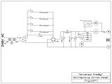
This information may be used entirely at your own risk.
There is always a way if there is no other way!
How do you determine the best value for R2 then?
The initially suggested 10 Ohm would cause a 250W heat loss at 5A.
Even a 0.1 Ohm resistor would heat up due to 2.5W power dissipation at 5A.
How about three 0R1 (5W) resistors in parallel, making it a 0.0333 Ohm resistor? Would that still smooth the ripple at all? Power dissipation at 5A would be 0.8333W, split evenly between the three resistors.
This information may be used entirely at your own risk.
There is always a way if there is no other way!
Hi Mik.
Your questions answered.
1. Rotary switch definitely needs to be rated at 400 volts or more
2. The capacitors C2 and C3 do most of the ripple reduction. (see below)
3. The back to back isolating transformer suggestion is valid for some applications BUT you need to allow for the maximum current conditions.
4. R1, (the resistor on the motor run capacitors) Each capacitor must have it's own resistor. Ideal resistor values would be as indicated below.
5 The 1 amp meter. You could switch shunts whilst in use to cover the ranges of current required. This would better protect the meter. There can also be high current surges due to the charged reservoir capacitors feeding into a low voltage load. A fuse in the output line would also offer valuable protection against surge currents.
Regarding the resistor R1. In the original design, the resistor value was chosen to discharge the capacitor after the power was switched off. If the capacitor were to remain charged (e.g. the power was switched off at peak positive on the incoming sine wave) it would first of all hold it's charge for some time and for servicing purposes, it would present a 'shock' hazard. BUT more importantly, if you were to re-connect the mains supply and the mains sine wave were in the negative half cycle there would be an extremely high current flow which could blow the input fuse and or damage /burn out the input switch and /or damage the motor run capacitor.
My original circuit was designed to discharge the capacitor in something over 8 seconds, and for my purposes this was felt sufficient. Switching the mains power off and then back on within 30 seconds wasn't envisaged. And opening the case for servicing would definitely take more than 30 seconds. I therefore considered the design acceptable.
The capacitor switches brings the possibility of rapid switch in and out of the capacitors. This is fraught with danger, not least to your capacitors and switches. The currents that can flow when capacitors of different charge levels are connected in parallel are very high, Hundreds of amps even.
The practical solution is to have a discharge resistor (on every capacitor) which will discharge them all in the same time scale. Then to follow a rigid routine of Switch OFF, Wait 40 seconds. Switch the capacitor combination and FINALLY switch ON.
I suggest that the discharge resistors should now be as per list..
for the 4 microfarad capacitor a 2.2M Ohm at 1/4 Watt (min)
for the 8 microfarad capacitor a 1.0M Ohm at 1/4 Watt (min)
for the 16 microfarad capacitor a 470K Ohm at 1/2 Watt (min)
for the 30 microfarad capacitor a 250K Ohm at 1 Watt (min)
These values will discharge the capacitors totally in 40 seconds and to relative safe levels in 10 seconds.
Ripple Reduction.
In the original circuit, the 8 microfarad input capacitor in conjunction with the 100 microfarad reservoir capacitor gives a maximum ripple of 12.7 volts (by calculation) the additional smoothing capacitor and resistor R2 reduce the ripple further to about 5.1 volts. The removal of the Resistor R2 will result in a final ripple of 6.3 volts. Not really a significant change.
HOWEVER. each increase in value of C1 (the motor run capacitor) will increase the ripple proportionately i.e. double the value of C1 = double the voltage of the ripple.
The Isolating transformers. Must be capable of the maximum currents drawn (this is irrespective of power factor). The current drawn by the original circuit, with the 8 microfarad capacitor, was 0.6 amps @240 volts supply. The addition of the extra (motor run) capacitors brings the possible current (all capacitors in circuit) to 4.37 amps. THIS CURRENT IS REAL- DESPITE BEING PHASE SHIFTED FROM THE INPUT VOLTAGE.
THE ISOLATING TRANSFORMERS PROPOSED WOULD NEED SECONDARY WINDINGS CAPABLE OF CARRYING 43.7 AMPERES.
A standard mains voltage isolating transformer would require windings capable of carrying 4.37 /5 amps. This would be the better option.
ElectricLou's ideal is useful for resistive circuits but is not always practical for highly reactive circuits such as this.
I hope that I haven't spoiled anyone's game.
Mik. I think the name of 'Universal Freddy' for this charger is cute.
Authors note: As I am 'de-rusting' my electronics knowledge in this forum, I am happy to be corrected where I may be, or am, mistaken. Please feel free to criticise.
The Laird
Thank you again for taking the time to answer questions!
Your fine Universal Freddy could be re-rigged on the fly, so one could equalize an entire 240s NiMH Prius MK1 battery with it.
Getting one of the first generation hybrids going again would be quite a feat!
.
I still don't understand the rotary switch problem in the more complex setup I drew up (you have almost talked me out of it by now...)...
What will happen to a rotary switch not rated for any particular voltage if it was placed in the position shown in the diagram? I just don't understand what possible problem could befall it!
This information may be used entirely at your own risk.
There is always a way if there is no other way!
It's astonishing what a large impact any small AC voltage fluctuations have on the current flow produced by the Universal Freddy, when it is operating at the upper end of the voltage range.
This is much more pronounced with the larger motor run capacitors which I am using for the Prius 240s NiMH battery.
A 30microF and a 16microF in parallel cause a much flatter "voltage vs current" curve than the 16microF capacitor in TheLairds original design.
When charging at 334V DC, the current can fluctuate between 0.20A and 0.32A, caused by small DC supply voltage fluctuations due to varying loads on the grid and in my house.
That, together with temperature fluctuations during day/night cycles in the garage, makes full SOC estimation based on voltage (under charging conditions) tricky.
But if one has enough time, it does not matter. The current will reduce until the battery dissipates the equivalent amount as heat, and it is such a low current, it could be left on for days without damage. Roughly about C/25 for this 6.5 Ah battery.
We put the equalized battery back into the car today and went for a test drive, it worked well! But only time will tell how long it will take for the battery to become unbalanced again.
This information may be used entirely at your own risk.
There is always a way if there is no other way!
Pages