What are the most common problems with electric motor design?
Well, the first problem is that rotary electric motors work better when they turn at higher rpm. This then forces the use of gear reduction and that introduces friction losses and reliability issues as well as additional noise. What would be ideal is some kind of very slow moving motor that ran at the same speed as human pedaling.
The solenoid is very interesting.
First, our usual motor design "constraint" is that all motors need to create circular magnetic flux paths to generate higher forces. In a cramped motor those paths have limited room to get around and so you are trying to shove something into a confined space. We try to adapt by using motor materials that are more permeable... but we can only go so far doing that.
For a Solenoid the interior field strength increases with number of turns of copper and with electric current.
What is INTERESTING is that the outside flux path grows in total area as the length of the Solenoid increases. This means the "flux density" of the outside approaches ZERO as the Solenoid length increases. Comprehend this... you can create incredibly high magnetic flux on the inside and have nearly zero "resistance" for the flux outside. You don't need a big heavy silicon steel "shell" to complete the outer loop because the flux is so dispersed that it flows on it's own in simple air. Air is lightweight, silicon steel is heavy, you get the point.
Within the inside area it's better to use a highly permeable material like silicon steel because that further increases the magnetic flux.
Place a strong neodymium magnet in the center of the Solenoid insides and surround that magnet with Silicon Steel on the edges. Now you have the "edges" amplified with better permeability and the core has a highly focused magnet.
You then create the circuitry that generates an alternating current in the Solenoid and you have the old fashioned steam engine.
Using clever design with ball bearings in the Solenoid ("piston") you reduce friction to near zero. You now have a slow moving steam engine like motor "piston" that could be connected to the bicycle cranks or the bottom bracket might be modified so that a freewheel could isolate motor and pedal power.
Chug, chug, chug, chug... :)
I would have to do some analysis using computer simulation to determine if it would be better to use more Silicon Steel in the core or more Neodymium Magnet to achieve maximum performance. My "guess" would be that the Neodymium Magnet should cover the entire "piston" stroke and no more and the excess edges would be Silicon Steel. Flux drops to zero outside the Solenoid.
.
Another issue the Solenoid can solve is the reliance on higher voltage.
In order to get a rotary electric motor to function you need to have fairly fast switching of polarity in order to get the motor to spin fast and become efficient. That works better with higher voltage and lower inductance.
In a steam engine styled Solenoid motor the "piston" moves at very slow speed and that allows the voltage to be lower and the inductance can be higher. Electrical components like these "soft" switching situations because the higher inductance slows the current surges.
In an ideal design the ebike might operate with only 4s (roughly 12 volts) and each cell could be very large in size. (20ah) Larger cells are more durable and balancing would be easier.
So the Solenoid contributes to the reliability overall.
You still will want to use Pulse Width Modulation because you still want precise linear control of power output, but the stresses on the MOSFETS should be low. Most controllers are nearly 95% efficient anyway.
Starting would require some pedaling because this would be a Single Phase motor.
There are plenty of hobbiest Solenoid motors visible on the internet.
Adapting this simple design to a bicycle wouldn't be terribly difficult.
Was thinking you could cut out the middle of the bottom bracket and insert the motor drive crank in the middle.
Another nice feature is that there is no cogging to worry about (no back iron) so you could skip the freewheel normally needed when the motor isn't running. (assuming you open the current path to allow energy to circulate)
But if the spindle / motor crank is rigidly attached to the crank arms you will have to pedal when the motor functions which forces this to be a pedelec ebike.
It's interesting because it's really simple and slow... good for an ebike because we want something that will last for thousands of miles without wearing out.
------------------
Pedelec Creates BackEMF
Here's where it could get even more interesting...
When you pedal the core of the Solenoid will move and as it does so it will create a BackEMF because a magnet moving past a wire does that. If the controller could measure this and use it as a signal for how much power to apply you have a built in "sensorless" control capability. This further reduces complexity (no hall sensors required) and that improves reliability.
In a pedelec the power is supposed to scale with the pedal force.
.
You begin by REMOVING the traditional chainstays that connect the bottom bracket to the rear wheel. You do this so that you can increase the size of the front chainring and not worry about clearance issues.
Next you replace the chainring with a high pole count axial flux motor that is made extremely thin. Ideally this is also an IRONLESS core (nothing but copper) which means that there will be very high efficiency because there is no hysteresis. Basically you are attempting to create a CSIRO / Launchpoint like motor, but with even higher pole counts. (60+ poles?) The higher pole counts allow for lower rpm operation which is necessary because human pedaling has a maximum of about 100 rpm. A Halbach Magnet configuration focuses the magnetic forces within the motor and removes the need for iron.
You still need a chainring and hopefully everything can be tucked in tightly. Many chainrings have room for three in parallel, so a single chainring combined with the motor should have room.
Only one freewheel would be required (on the motor) because pedaling a motor without cogging will not produce the annoying cogging resistance.
.
By using an iron (steel) front chainring you automatically have all you need to create a Switched Reluctance Motor because the teeth of the chainring create alternating flux paths of high and low.
My guess is that Four Phase (not three) would give the best results because Switched Reluctance Motors have about half as many active states as permanent magnet motors.
One advantage is that longer wait states allows for lower hysteresis and that means you can use those really high magnetic flux materials that tend to have higher Remanence. High Remanence is a big headache on high rpm rotary motors because it costs energy to bring Silicon Steel back to a demagnetized state once you charge it up.
2.0 Teslas is roughly double what ordinary Silicon Steel produces, but it only makes sense if you have those long wait times. Also note that you get to 2.0 Teslas really quickly.
It's a very attractive idea because you could just bolt on a kit.
(for 250 watt ebikes this seems ideal)
----------------
Note: It might actually prove more effective if the steel chainring is specially designed to maximize the alternating flux. It might even be possible to get inventive with the chainring and consider advanced materials. There's no reason it has to be all iron. (only the high magnetic flux areas need to be iron)
.
...continuing the Switched Reluctance Motor concept:
I'd probably use square shaped holes rather than round. The idea would be to use a standard aluminum chainring, then "stamp" in iron plugs in the holes sort of like rivets. Those iron plugs are then more massive and that increases the maximum magnetic flux capability.
Also, you might flip the coils to the opposite side and surround the chain side. (on the previous post I had the coils inside the chain)
Since the iron plugs can be wider than the chainring you should be able to install the coils above the chain, making life easier.
But what if you used a Stepper Motor design concept:
Talk about what appears to be a "perfect fit".
You could use a simple steel chainring then build coils that match the standard spacing. If the chain is made of a metal other than iron (like aluminum) the outside of the chainring could be used. If not, then the empty inside space (like two posts ago) would have to suffice.
Stepper Motors are capable of very slow speeds. (their best feature)
Mild steel is very flexible, but it creates eddy currents when a magnetic field changes direction within it and that creates heat. Transformers and motors require lower electrical resistance in order to prevent eddy currents, so they add a small amount of silicon to the steel.
A chainring "could" be built with Silicon Steel.
One problem is that Silicon Steel is more brittle which means the teeth might break and if you bend the chainring too much it might crack. In motors and transformers they try to use really thin laminations which is impossible here. However, though imperfect I'd guess it would work "good enough" because this is a stepper / switched reluctance motor and the switching is slower.
Outward Facing Radial Halbach Array Chainring Motor
OFRHACM?
Inrunner Chainring?
Whatever you want to call it.
The goals here are:
1) Must be a solution (mid drive) that bolts on without frame modification.
2) Must improve on geared solutions that involve friction and reliability issues.
3) Must have potentially high efficiency while preventing weight gain.
-----------------
So the idea here would be to "sacrifice" a chainring to the dedicated purpose of being the active motor. The inner chainring (standard and separate) would actually drive the chain. Double freewheels on the crank would allow either pedal propulsion or motor propulsion or both.
Why radial? What's wrong with axial?
There's very little room to fit a motor in place of a standard chainring. Axial flux motors actually have to be wider than we want because the flux creates circles going that go perpendicular to the chain path. The radial design (combined with an inside Halbach Array) concentrates the flux into a tight space and directs it outward.
Another factor is mounting.
A radial motor is much easier to mount because it will naturally center itself. One would first mount the chainring (which holds the magnets) and spend some time making sure it rotated perfectly true. You then mount the stator (coils) which would bolt onto the frame with clamps. The clamps would have a "rough mount" aspect to bolt to the frame and some kind of fine adjustment when doing the final adjustments.
High pole counts (50 poles?) will produce a slow moving motor.
----------------
The positive aspect of this design is that you generate more power with less weight. The negative is that you reintroduce cogging which forces double rather than single freewheels. You also "sacrifice" a chainring rather than reuse one.
High efficiency and low weight tip in favor of this design. People wanting to generate more power would be pushed towards this too.
.
There are several ways to generate force with magnetism. You can do it through attraction and repulsion of permanent magnets. Another way is to get things to "align" because of a magnetic field. Typically the motor designer picks one or the other and designs a motor around his choice.
What makes the Lavet Type motor interesting is that it uses both.
I'm still dreaming up how you might use this, but here's my first idea:
Install a very high powered magnet inside the bottom bracket. Then surround that magnet with the necessary silicon steel as seen in the image. Copper coils are also added. Now you have a simple Single phase pedelec which can be run with a single Hall sensor.
...will have to think more on this one.
It's very simple, super reliable, and should be fairly efficient.
Keep in mind these are used in clocks (pendulum) and require little energy to operate. Since pedaling resembles the motion of a clock ("tick, tick, tick, tock") the idea holds promise.
Like some other ideas I've seen this uses the permanent magnet to activate the silicon steel, so the coils aren't required to fully energize it. The coils for the most part "push" the magnets over their setpoint state and once past the center the magnet propels itself. This creates a motor with a single "cog".
Dimensions: 1" x 1" x 1" thick
Tolerances: ±0.004" x ±0.004" x ±0.004"
Material: NdFeB, Grade N42
Plating/Coating: Ni-Cu-Ni (Nickel)
Magnetization Direction: Thru Thickness
Weight: 4.34 oz. (122.9 g)
Pull Force, Case 1: 76.41 lbs
Pull Force, Case 2: 76.41 lbs
Surface Field: 5754 Gauss
Max Operating Temp: 176ºF (80ºC)
Brmax: 13,200 Gauss
BHmax: 42 MGOe
...I've bought some really small cube shaped magnets in the past that were just 1/4" x 1/4" x 1/4" and they were "scary strong", so a full one inch cube would be dangerous to handle. But at only 4 ounces you get a strength equal to over 75 lbs. That's just nuts.
So you could build a bottom bracket based Lavet motor and not need much space. It seems like the simplicity and (apparent) efficiency makes it an idea to look into. I'm going to have to get my old PC running again to do FEMM simulations.
Since the magnet does the majority of the energizing of the silicon steel the coils electrical energy contributes mostly to rotating the crank. It's a little like "Parallel Path" motors which did some interesting things.
What they found with "Parallel Path" is that very little magnet was needed to achieve a great deal. So a one inch cubed hunk of magnet might be excessive... and 4 ounces too much. Neodymium magnets can actually generate so much magnetic flux that silicon steel will saturate.
Good news for QM Power ("Parallel Path" motor builders) they just got more grant money:
QM Power will design, build and test a high performance 3kW alternator using Parallel Path Magnetic Technology (PPMT) with no at risk rare earth magnet materials that is smaller, lighter and more efficient than the existing alternator that uses rare earth magnets.
While the shape smooths somewhat when we compare Beginner, Intermediate and Expert cyclists the basic pattern remains the same. Power is not delivered smoothly on a bicycle.
It's "abnormal" to have smooth power delivery as a cyclist and so maybe an electric bike should be designed so as to acknowledge this fact?
The Lavet Stepper Motor is very efficient because the silicon steel is mostly charged by the magnetism of the magnets. (like with Parallel Path) Since the charging and discharging of the silicon steel is a major factor in efficiency losses (other than the coils which are the main source) we can attain higher efficiency at slower speeds.
Power = Force * Velocity
...for a cyclist the pedal Velocity is limited to about 100 rpm. So if we aren't going to use geardowns from motor to crank we need to generate a very large Force in a direct drive crank. This means powerful magnets and significant cogging.
Seems to me you could align the cogging at the same angle as the pedal diagrams suggest. You would then have a motor that acknowledged the pedal power in it's irregularity. (in other words peak cogging would be at 45 degrees)
----------------
Could be a topic all it's own...
Silicon steel takes a lot of energy (applied by the coils normally) to get charged up enough to be able to do useful work. When you rely on the coils to create all the magnetic flux in the silicon steel it wastes a lot of energy. However, if you use magnets to charge up the silicon steel you do not need to use the coils and that represents a savings. This is the "core idea" of Lavet Stepper Motors and of Parallel Path Motors. Permanent magnets do most of the "work" and the coils are reduced to the role of "flux path switching". Some call this like "magnetic transistors" because that's an analogy that fits pretty well.
You need to be careful about using too much magnet because it can saturate the silicon steel and reduce overall efficiency. (over 1.2 Teslas is probably too much)
Does a good job of comparing the Permeability vs the maximum Flux.
You want your magnets to get you charged up, but not too much.
.
This seems like such a no-brainer that I'm not sure why it's not being done.
Make use of the disc brakes by turning them into little Switched Reluctance Motors !!!
Maybe the disc will need some redesign to make things more efficient, but other than that you have everything already there.
In the image the RED blob is a set of coils that would activate so that the wheel will want to align to minimize magnetic resistance (reluctance). In order to align, the wheel must rotate and that generates a force either forward or reverse depending on the timing. For forward motion you time all coil pulses to "pull" the disc forward. For braking you could time the pulses to "push" the disc the other way.
The disc will want to move it's "thickest metal" to the center of the magnetic flux created by the coils. (but not magnets in this case)
You will probably need an optical sensor rather than a hall effects sensor because this does not use magnets at all.
Weight added is just the coils. My guess is about a kilogram (2.5 lbs) per disc.
--------------
This could function like a KERS device (regen) but I would guess that manual braking might need to be implemented for safety reasons. If your battery fails you need manual brakes as backup.
I would design the entire system based on Android (java) with a smartphone. With full computer control and "fly by wire" thinking you should be able to deal with the enormous complexity of having Switched Reluctance on both wheels.
Traction control?
Sure... would make climbing a slippery hill easier on a mountain bike.
And you can also use KERS type braking with anti-lock.
Compared to mid drives with geardowns the mechanical complexity is much lower. But you reintroduce complexity with the software. It's much easier to develop a simplified platform (in software) and then slowly add new layers (KERS, anti-lock) as you go. As long as you test each new layer fully and keep all the versions backed up as you go you are fine. Use "best practices" in software development.
.
The Switched Reluctance Motor has positives and negatives. The biggest positive is that the efficiency can be very high even though the motor design is very simple.
The "trick" is to know exactly when and how much current needs to be delivered to the coils.
* If you are perfect the motor works efficiently.
* If you overshoot with late or excessive current you will produce waste.
* If you intentionally pulse late it behaves as an efficient generator.
...and all these factors change "shape" as the motor varies it's rpm.
Keep in mind this is just one 3D profile for a given rpm. As the rpm rises and falls the shape moves all over the place.
So computers are essentially the ONLY way to do this.
I'd probably embed an ultra high speed PWM mini-controller within the coils themselves and then use the Android smartphone to control the "current". (at a slower computational speed). Trying to actually do the pulse width modulation in the software itself would probably exceed the limits of the cpu. What matters most is the lookup tables which a computer is capable of doing. Those tables would be entirely specific to the actual coils in use.
One more thing:
Coils (electrical) behave like "Springs" when you charge them up. This is called "Inductance" and in a Switched Reluctance Motor you are in a very difficult position because at the very time you want to charge up your coils the inductance is INCREASING. (inductance increases as the flux linkage increases as the rotor moves closer) Once you pass your optimal coil charge state the inductance reverses and DECREASES.
So it's like slamming into a wall, then suddenly falling off a cliff !!!
The timing must be perfect and the pulse size must be perfect, anything less than perfection (in any direction) will detract from either efficiency or power output.
This is not easy, but it's such a "modern world" thing to do... :)
The D-Drive Infinitely Variable Geared Transmission
This is amazing !!!
Since the beginning of motor vehicles we have come to accept that the only way to have gears is through fixed gears that are shifted between. Variable transmissions have existed, but have been fairly lame.
Steve Durnin (inventor and full patent holder... do not steal) has devoted his free time as a hobby for 20 years working on the idea and has finally found an answer.
As best as I can understand the transmission uses two planetary gears and two shafts to deliver torque. The forward, neutral or reverse motion is defined by the "relationship" of the two shafts rotating.
I'd guess this is roughly thinking at a 200 IQ level.
Watch the video... if you understand it you have a strong mind. :)
Brilliant men for over a hundred years have attempted to solve this problem and this guy comes along and solves it.
Proves that one man can potentially change the world.
-----------------
You need "external drives" that operate on each of the shafts. These basically rotate the planetary gears so as to alter the gear ratio. They don't need to be any stronger than is required to overcome friction within the device. It's definitely "out of the box" thinking because in order for it to operate you need these extra inputs. They will slightly detract from efficiency... but hardly at all.
...think of how an ice skater does a spin. They change the speed of rotation by pulling themselves closer to the axis of rotation. With this D-Drive it's like two ice skaters that are working together. The skaters must supply "input" to alter the spin. (it would be interesting to hear what was his actual inspiration for the idea... it likely had a physical analogy)
...planetary eliptical orbits are another physical analogy.
One of the problems with new ideas that few can "grasp" is that people are reluctant to take risks with things they can't understand. If I was the guy who invented the idea I'd spend some time developing a physical analogy that people can visualize. However, if a big auto company licenses the idea and simply builds it into a car the concept could slip into use with little marketing. It's an ideal automatic transmission for a car.
It's hard to get over how brilliant this is, great work Steve Durnin !!!
Okay, I'm going to try to create an easy to understand explanation for the D-Drive.
Imagine the inner gear and outer ring as each being independently rotated by the two shafts.
* If the outer shaft spins clockwise then the "output" gear also spins in a clockwise direction relative to the center.
* If the inner shaft spins clockwise then the "output" gear also spins in a clockwise direction relative to the center.
...go counter-clockwise for both and you get counter-clockwise "output" for both.
* If the shafts are spinning exactly opposite to each other the "output" stays still, this is neutral.
-------------------
An animation could make this really easy to understand.
Just think of the two shafts as totally independent and "floating in air".
The eliptical aspect of the D-Drive is simply to "reconcile" what's going on otherwise. It's the eliptical part that is the "hard part", but the variable gearing is explained by a single planetary gear.
Toyota has been using a similar kind of setup right from the first Prius to this day in their "Hybrid Synergy Drive" system, in order to simulate an infinately meshable gearbox for the ICE. The electic motor changes the ratio for the ICE, but of course it also adds it's own power into the equation. The D-Drive takes this concept just one step further, which is it's main merit.
My rides:
2017 Zero S ZF6.5 11kW, erider Thunder 5kW
Wow! I did not know that, I had thought the gas engine simply ran a generator and the Prius was basically an electric car. There is a generator, but a lot more too. I'm more impressed with the Prius than before.
This is so simple of an idea it would work on an ebike. Take two electric motors and blend their output through a planetary gear. Each motor could turn very slowly since when they combine they magnify their output speed.
Makes you wonder why so many seem attracted to the NuVinci hubs.
The biggest problem with small motors is they need to spin fast in order to develop power and efficiency.
If you had the planetary gear set up with one motor on each of the two gear sets and those motors could spin so as to OPPOSE each other (slowing output to a crawl) then they can run at high rpm even though the output is at a low rpm. As the ebike accelerates you slow one of the motors which will produce a gradually increasing output. Finally the slowing motor reaches a stop and you can reverse it's direction which will add to the output speed.
Two small RC motors could work very well. (reduces torque during starting) My guess is that some unevenness in gear ratios of the two motors could be a benefit as one could be the primary drive and the other the secondary. They might use different kv's too.
In case someone missed the point of this:
You will NOT NEED TO GEARDOWN this system.
(this has been a big issue for ebikes)
Mechanically this requires a single planetary gear and nothing else. Controlling the two motors will require some effort, but it doesn't look that difficult. Easier than many. The easiest way would be to use speed sensors on the two motors and have some logic about how to control them. I'd be a little worried about the low speed ---> zero ---> reverse phase transition because that motor will be passing through a less efficient power range. One might "jump" across that and have the other motor adjust dynamically. Some tuning will be required.
Using a brushless motor as the primary drive and a stepper motor (servo) as the other might be better because stepper motors deal with reversing better. If the stepper motor can be geared lower than the primary motor it can be made smaller. Lower gearing can be done by the way this motor is connected to the planetary gear. But this is where the D-Drive would be better because your inputs are not required to deliver any more power than is required to overcome friction.
This is technically easier than Switched Reluctance motors. (the most difficult)
.
This is how a motor behaves when it is connected with a direct drive and geared to maximize speed for 1000 watts. (and a bunch of other assumptions about things like aerodynamics)
Notice how at low motor rpm (which in direct drive means low mph) the majority of the power output ends up becoming heat.
Okay now assume we are using two motors through a planetary gear and these motors work opposite of each other so that during "idle" they are both running near their highest rpm, the no load speed.
It should be clear that these motors will "share" current as they work together and that collectively they will produce more net power with less heat because they are running at higher rpm.
As one motor is made to slow it will actually draw more amps which opens the potential problem of efficiency going DOWN as overall speed goes up. The D-Drive skillfully gets around this problem, which makes it clear that it's a good idea.
Will have to think if there's a better way to do this.
I'm sort of thinking an alternator type secondary motor with field coils would work. That way the drive motor "spins" the alternator at idle and the field coils are barely energized. As you wish to slow the alternator you would increase the field coil strength which creates more generator power and you get a sort of "turbo like" feedback that slows this secondary motor. Since an increase in the field coil strength means more magnetism it's like the reverse of "field weakening".
--------------
As I think of different ways to do this I get caught in "perpetual motion machine" traps. The bottom line is the secondary motor needs to be able to slow down and yet maintain the same overall power output as the primary motor. Since Power = Torque * RPM as the secondary slows a corresponding increase in torque is required. Increases in torque typically involve efficiency losses.
The D-Drive is really a breakthrough because it removes the torque out of the equation.
Possibly some kind of permanent magnet could act as a "brake" which would provide the necessary reversing torque, but I'm not sure how. Cogging as a "brake" only is useful at slow speeds.
This might not be a very good solution after all if no way can be found to slow the secondary motor without suffering a big efficiency loss.
---------------
In the Prius the primary motor is a gas motor. The secondary motor acts like a generator. Since the gas primary is generally inefficient compared to electric motors and generators it's still a step up in overall efficiency. But with two electric motors you aren't getting much benefit.
.
Electrical hysteresis units have an extremely wide torque range. Since these units can be controlled remotely, they are ideal for test stand applications where varying torque is required. Since drag torque is minimal, these units offer the widest available torque range of any of the hysteresis products. Most applications involving powered hysteresis units are in test stand requirements.
When electricity is applied to the field, it creates an internal magnetic flux. That flux is then transferred into a hysteresis disk passing through the field. The hysteresis disk is attached to the brake shaft. A magnetic drag on the hysteresis disk allows for a constant drag, or eventual stoppage of the output shaft.
When electricity is removed from the brake, the hysteresis disk is free to turn, and no relative force is transmitted between either member. Therefore, the only torque seen between the input and the output is bearing drag.
So basically you apply a coil to a disc and get a sort of reversed induction motor. The advantage of this is that it's simple and if it's fairly efficient in creating a reverse torque then it could make the planetary gear motor idea possible. You would have the primary motor (brushless DC) and this magnetic hysteresis power brake.
As long as the efficiency was good it could work, not sure about that.
Small RC motors burn up because of heating at low rpm, so this definitely removes that as an issue, but as the hysteresis power brake is applied and the final output increases speed you will be increasing energy "cost" but not to the fragile little RC motor. You end up redistributing losses.
So in effect you set the RC motor to "on" (it's ideal rpm) and the throttle would control the hysteresis power brake. Weird, but it might work.
RC motors also have weak bearings, so this helps there too.
Okay so I'm contemplating this hysteresis power brake concept and wondering how much power I'd waste doing it and see the commercial for the Proform exercise bike.
Why not replace the coil in the hysteresis power brake with a strong permanent magnet?
This is exactly what the Proform exercise bike does with it's Silent Magnetic Resistance.
The permanent magnet USES NO POWER.
Your "throttle" will be mechanical because you will accelerate by moving the permanent magnet closer to the disk which will likely surround the planetary gear.
The small motor can be run at a constant optimal rpm at all times.
---------------
This is actually a good idea after all.
1) Maximum motor efficiency at all times.
2) Mechanically driven throttle connected to powerful permanent magnet.
3) Low rpm power output from planetary drive for high torque.
4) Infinitely variable transmission.
* * * Magnet Strength = Motor Current Limiting * * *
The motor will develop torque and draw current based on it's load. We not want to exceed the maximum desired current for the motor at any time. Therefore, one primary design criteria is that the permanent magnet that creates the hysteresis in the disk cannot create a counter torque greater than a desired amount when it is fully engaged.
The magnet must be matched with the motor.
This is how we implement "current limiting" in the system.
One bases this on "full throttle" conditions where the magnet fully engages with the disc. In less than "full throttle" the counter torque will be below the maximum and the current will be below our limit. Basically it will work like a normal ebike.
By changing the magnets to those with differing strengths we adjust our "current limit".
.
What you (and apparently others too) are calling a hysteresis brake is based on eddy currents within the retarder disc which the permantent magnet induces. Those eddy currents will heat up the disc. And where there is heat there must also be an energy source to produce that heat. That energy source is your motor that can wonderfully run at "a constant optimal rpm".
You could get the same effect from brake padds that you press onto the disc at varying force. The only upside of the eddy current retarder is that very little force is necessary to move the permanent magnet in and out, especially if it can move on roller-type bearings that bear the brunt of the braking force, and it is pretty immune to wear an tear.
My rides:
2017 Zero S ZF6.5 11kW, erider Thunder 5kW
Copper loss and excessive torque are the big problems on a small motor.
Notice how small hysteresis loss is in the motor itself. (No Load Loss)
Let's say (for instance) that you apply the magnet to the disc (as the motor runs optimally) and it generates eddy currents that shed 10 watts per pound in the form of heat. What isn't lost as "slip" through the eddy currents ends up delivering the desired counter rotational torque that accelerates the ebike.
If that's the case (and I suspect it is) then it's a pretty good "trade".
Copper losses can be overwhelmingly bad at low rpm, so this simply "trades" some small eddy current hystersis loss in exchange for more optimal motor rpm. It should be no worse than induction motors that can achieve very good efficiency. Some experimenting with disc materials might be required.
It's a fascinating way to achieve infinitely variable gearing too.
----------------
RC motors are also designed for things like model airplanes which run mostly within a narrow rpm range. When you try to "grunt" the motor at low rpm they can't handle the strain for long. The ESC's are also not very good with widely varying conditions so most people end up adding hall sensors.
It would be an interesting project for an RC motor.
Eddy currents are a separate (and real) thing, but I don't believe the Hysteresis Power Brake is dependent on them. (or they might call it a Eddy Current Power Brake)
Laminations can reduce eddy currents.
Hysteresis could "in theory" exist without eddy currents if laminations were thin enough.
It seems like Hysteresis braking better fits the problem. With a flat torque curve you can implement a kind of "current limiting" that will protect the motor from overheating.
Add in the fact that the torque is applied through the throttle and you should be set.
The only losses I can see come from the difference between torque delivered verses torque applied and that loss shows up as "slip" and produces a small amount of heat. Using something like Silicon Steel and laminations should reduce eddy current losses. Laminated Silicon Steel typically produces less than 10 watts per kilogram of heat (often much less) so it should be small.
.
.
However, there's also an argument that some mixture of Hysteresis and Eddy Current techniques could achieve a better result.
.
.
With ebike controllers we typically distinquish between "battery side" and "motor side" current limiting and I think we are in a similiar situation. However, once you start to allow excessive currents into the motor you sort of reintroduce all the problems you were trying to fix.
If I were building one I'd use Hysteresis only... then consider testing other ideas afterwards.
You could get the same effect from brake pads that you press onto the disc at varying force. The only upside of the eddy current retarder is that very little force is necessary to move the permanent magnet in and out, especially if it can move on roller-type bearings that bear the brunt of the braking force, and it is pretty immune to wear and tear.
Basically you are describing a standard mechanical clutch.
I think the question becomes one of output efficiency.
How much torque is transmitted to the output and how much heat is lost in the process?
For gasoline motors there is an expectation of having major losses in multiple areas, but the amount of power the gasoline motors create is so large that they tend to (until recently) not care much.
Also we might be talking about low torque levels with a Hysteresis type clutch. If the gasoline motor is producing 200 hp a Hysteresis type clutch might need to be too big and heavy to be practical.
With an ebike we care a great deal about efficiency and weight, so it needs to be proven which system is best. For 1000 watts of output we are not going to be happy if more than 25 watts of heat is lost through hysteresis. At 25 watts we are only talking about 2.5% loss.
* * * At low rpm for a motor with fixed gearing the losses are:
~ 400 watts to copper loss
~ 10 watts to hysteresis loss inside the motor
~ 40 watts to the chain / sprocket / gears
...overall efficiency becomes ~55%
* * * With this Hysteresis Planetary Gear motor the losses are:
~ 100 watts to copper loss (or less)
~ 35 watts to hysteresis loss inside the motor (higher rpm)
~ 40 watts to the chain / sprocket / gears
~ 25 watts to the hysteresis clutch
...overall efficiency becomes ~80%.
----------------
It's about a 25% reduction in "overall losses" at low rpm (like climbing a hill) but it's subtracting from copper loss which is the most dangerous for the small motors, so it's really addressing the most critical aspect of losses.
Truth always ends up being more complicated than you first expect.
Above is the Heat Dissipation equation for a Hysteresis Clutch.
On the left side (Pv) we have the actual heat in Watts that will be created by using this clutch. On the right on the bottom we have what seems like a strange constant of 9.55. What the heck is that you might say? Well, it's really just there to convert rpm values into radians per second, so you don't need to feel it's very mysterious.
Next we tackle the "slip" variable "s". If the clutch is rigidly clamped down so that no slip is taking place then no heat will be created. If there is no slipping going on then s=0. On the other extreme we might have a clutch that is not applying any torque at all and is "free spinning" which means that "slip" is at a maximum and s=1.
Things begin to get interesting as we apply some torque transfer into the system. In theory "slip" can be at it's maximum meaning the drive side is "free spinning", but it requires some power in the form of drag to maintain that speed. In such a case this is more like a brake.
Simplified we get:
Heat (Pv) = Torque (T) * Motor Rpm (ns)
...so for a given Torque the faster you run the motor the more linear heat you dissipate.
For a clutch things are a little different.
As we begin to actually transfer some rotation into the output side of the clutch our "slip" begins to decline. The relative rotational difference (ns) goes from 100% of the Motor Rpm (like with the brake) to an Output Rpm that is some amount less.
Here's where things begin to get weird...
A Hysteresis Clutch cannot be driven with heat to infinity. Like with an electric motor you have limits to how hard you can drive them and generally they must be kept cool and not driven harder than some value of Pv.
What this means is that what I was thinking in previous postings was overly simplistic. You can't so easily assume that a Hysteresis Clutch will deliver a simple heat dissipation.
The idea of have "current limiting" through use of the Hysteresis Clutch may have merit on the motor side, but now we have another issue to worry about which is the CLUTCH itself overheating. (didn't think of that)
---------------
So let's try some real numbers for the idea...
On the motor side let's say we started with 1000 watts of electrical power before we get to the motor. After losses the the motor delivers 90% efficiency (900 watts) at 6000 rpm. Using that 9.55 conversion (let's call it 10 for simplicity) we get:
6000 rpm / 10 = 600 radians per second.
Power = Torque * Radians per second
900 watts = Torque * 600 radians per second
So Torque = 1.5 Newtons
The planetary gear creates a 3-to-1 geardown...
Which means on the output side (the side where the clutch will be) the numbers become:
600 radians per second becomes 200 radians per second.
1.5 Newtons becomes 4.5 Newtons.
Now we have to "decide" how much heat the clutch will dissipate. Let's say we allow the clutch to dissipate a maximum of 100 watts of heat.
We then decide on the "slip" we will accept. This would be like our "throttle". Let's say we want our "slip" to be at 15%. So the value of ns will be:
200 radians per second at 85% is 170 radians per second and s=0.15
So:
100 watts = Torque * 170 radians per second * 0.15
...so the overall efficiency comes out roughly equal to direct drive BUT the heat is now being generated primarily in the clutch rather than the motor.
Is it worth it? I'm not so sure... not the result I wanted. :(
Seems these Hysteresis Clutches create a lot more heat than I hoped.
For an RC motor that works best at optimal rpm I can see some benefit in that you can drive the motors with more speed and reduce bearing loads, but ultimately the clutch ends up being:
Before ending the Hysteresis Clutch idea I need to go back to the D-Drive.
The "problem" has always been that when you try to implement some form of infinitely variable transmission you end up "fighting" one type of torque with another.
What makes the D-Drive so interesting is that the inputs are entirely independent of each other and that actually solves the problem.
The Hysteresis Clutch essentially "exposes" what the old problems were and doesn't really solve them.
...but what the heck, I gave it my best shot. ;)
-----------------
Hysteresis Clutch Performance (based on previously described planetary gear)
.
Assuming I got the math right... it looks like heat dissipation (left) is not too bad when the "slip" is fairly low. But as "slip" approaches 100% things get really ugly and heat rises exponentially.
The idea fails at low rpm... the very area it was supposed to fix.
.


Solenoid
What are the most common problems with electric motor design?
Well, the first problem is that rotary electric motors work better when they turn at higher rpm. This then forces the use of gear reduction and that introduces friction losses and reliability issues as well as additional noise. What would be ideal is some kind of very slow moving motor that ran at the same speed as human pedaling.
The solenoid is very interesting.
First, our usual motor design "constraint" is that all motors need to create circular magnetic flux paths to generate higher forces. In a cramped motor those paths have limited room to get around and so you are trying to shove something into a confined space. We try to adapt by using motor materials that are more permeable... but we can only go so far doing that.
For a Solenoid the interior field strength increases with number of turns of copper and with electric current.
What is INTERESTING is that the outside flux path grows in total area as the length of the Solenoid increases. This means the "flux density" of the outside approaches ZERO as the Solenoid length increases. Comprehend this... you can create incredibly high magnetic flux on the inside and have nearly zero "resistance" for the flux outside. You don't need a big heavy silicon steel "shell" to complete the outer loop because the flux is so dispersed that it flows on it's own in simple air. Air is lightweight, silicon steel is heavy, you get the point.
Within the inside area it's better to use a highly permeable material like silicon steel because that further increases the magnetic flux.
http://cnx.org/content/m42382/latest/?collection=col11406/latest
Now take it a step further...
Place a strong neodymium magnet in the center of the Solenoid insides and surround that magnet with Silicon Steel on the edges. Now you have the "edges" amplified with better permeability and the core has a highly focused magnet.
You then create the circuitry that generates an alternating current in the Solenoid and you have the old fashioned steam engine.
Using clever design with ball bearings in the Solenoid ("piston") you reduce friction to near zero. You now have a slow moving steam engine like motor "piston" that could be connected to the bicycle cranks or the bottom bracket might be modified so that a freewheel could isolate motor and pedal power.
Chug, chug, chug, chug... :)
I would have to do some analysis using computer simulation to determine if it would be better to use more Silicon Steel in the core or more Neodymium Magnet to achieve maximum performance. My "guess" would be that the Neodymium Magnet should cover the entire "piston" stroke and no more and the excess edges would be Silicon Steel. Flux drops to zero outside the Solenoid.
.
Low Voltage
Another issue the Solenoid can solve is the reliance on higher voltage.
In order to get a rotary electric motor to function you need to have fairly fast switching of polarity in order to get the motor to spin fast and become efficient. That works better with higher voltage and lower inductance.
In a steam engine styled Solenoid motor the "piston" moves at very slow speed and that allows the voltage to be lower and the inductance can be higher. Electrical components like these "soft" switching situations because the higher inductance slows the current surges.
In an ideal design the ebike might operate with only 4s (roughly 12 volts) and each cell could be very large in size. (20ah) Larger cells are more durable and balancing would be easier.
So the Solenoid contributes to the reliability overall.
You still will want to use Pulse Width Modulation because you still want precise linear control of power output, but the stresses on the MOSFETS should be low. Most controllers are nearly 95% efficient anyway.
Starting would require some pedaling because this would be a Single Phase motor.
(reversed rotation is a problem)
.
There are plenty of hobbiest Solenoid motors visible on the internet.
Adapting this simple design to a bicycle wouldn't be terribly difficult.
Was thinking you could cut out the middle of the bottom bracket and insert the motor drive crank in the middle.
Another nice feature is that there is no cogging to worry about (no back iron) so you could skip the freewheel normally needed when the motor isn't running. (assuming you open the current path to allow energy to circulate)
But if the spindle / motor crank is rigidly attached to the crank arms you will have to pedal when the motor functions which forces this to be a pedelec ebike.
It's interesting because it's really simple and slow... good for an ebike because we want something that will last for thousands of miles without wearing out.
------------------
Pedelec Creates BackEMF
Here's where it could get even more interesting...
When you pedal the core of the Solenoid will move and as it does so it will create a BackEMF because a magnet moving past a wire does that. If the controller could measure this and use it as a signal for how much power to apply you have a built in "sensorless" control capability. This further reduces complexity (no hall sensors required) and that improves reliability.
In a pedelec the power is supposed to scale with the pedal force.
.
Axial Flux Motor (replaces front chainring)
Okay, this is another idea...
You begin by REMOVING the traditional chainstays that connect the bottom bracket to the rear wheel. You do this so that you can increase the size of the front chainring and not worry about clearance issues.
Next you replace the chainring with a high pole count axial flux motor that is made extremely thin. Ideally this is also an IRONLESS core (nothing but copper) which means that there will be very high efficiency because there is no hysteresis. Basically you are attempting to create a CSIRO / Launchpoint like motor, but with even higher pole counts. (60+ poles?) The higher pole counts allow for lower rpm operation which is necessary because human pedaling has a maximum of about 100 rpm. A Halbach Magnet configuration focuses the magnetic forces within the motor and removes the need for iron.
You still need a chainring and hopefully everything can be tucked in tightly. Many chainrings have room for three in parallel, so a single chainring combined with the motor should have room.
Only one freewheel would be required (on the motor) because pedaling a motor without cogging will not produce the annoying cogging resistance.
.
Switched Reluctance Motor
By using an iron (steel) front chainring you automatically have all you need to create a Switched Reluctance Motor because the teeth of the chainring create alternating flux paths of high and low.
http://en.m.wikipedia.org/wiki/Switched_reluctance_motor
My guess is that Four Phase (not three) would give the best results because Switched Reluctance Motors have about half as many active states as permanent magnet motors.
One advantage is that longer wait states allows for lower hysteresis and that means you can use those really high magnetic flux materials that tend to have higher Remanence. High Remanence is a big headache on high rpm rotary motors because it costs energy to bring Silicon Steel back to a demagnetized state once you charge it up.
2.0 Teslas is roughly double what ordinary Silicon Steel produces, but it only makes sense if you have those long wait times. Also note that you get to 2.0 Teslas really quickly.
http://en.m.wikipedia.org/wiki/Remanence
It's a very attractive idea because you could just bolt on a kit.
(for 250 watt ebikes this seems ideal)
----------------
Note: It might actually prove more effective if the steel chainring is specially designed to maximize the alternating flux. It might even be possible to get inventive with the chainring and consider advanced materials. There's no reason it has to be all iron. (only the high magnetic flux areas need to be iron)
.
...continuing the Switched Reluctance Motor concept:
I'd probably use square shaped holes rather than round. The idea would be to use a standard aluminum chainring, then "stamp" in iron plugs in the holes sort of like rivets. Those iron plugs are then more massive and that increases the maximum magnetic flux capability.
Also, you might flip the coils to the opposite side and surround the chain side. (on the previous post I had the coils inside the chain)
Since the iron plugs can be wider than the chainring you should be able to install the coils above the chain, making life easier.
.
Same basic chainring centered design...
But what if you used a Stepper Motor design concept:
Talk about what appears to be a "perfect fit".
You could use a simple steel chainring then build coils that match the standard spacing. If the chain is made of a metal other than iron (like aluminum) the outside of the chainring could be used. If not, then the empty inside space (like two posts ago) would have to suffice.
Stepper Motors are capable of very slow speeds. (their best feature)
250 watts doesn't seem too hard to achieve.
There is no cogging. (no magnets)
.
Silicon Steel
Mild steel is very flexible, but it creates eddy currents when a magnetic field changes direction within it and that creates heat. Transformers and motors require lower electrical resistance in order to prevent eddy currents, so they add a small amount of silicon to the steel.
A chainring "could" be built with Silicon Steel.
One problem is that Silicon Steel is more brittle which means the teeth might break and if you bend the chainring too much it might crack. In motors and transformers they try to use really thin laminations which is impossible here. However, though imperfect I'd guess it would work "good enough" because this is a stepper / switched reluctance motor and the switching is slower.
.
Outward Facing Radial Halbach Array Chainring Motor
OFRHACM?
Inrunner Chainring?
Whatever you want to call it.
The goals here are:
1) Must be a solution (mid drive) that bolts on without frame modification.
2) Must improve on geared solutions that involve friction and reliability issues.
3) Must have potentially high efficiency while preventing weight gain.
-----------------
So the idea here would be to "sacrifice" a chainring to the dedicated purpose of being the active motor. The inner chainring (standard and separate) would actually drive the chain. Double freewheels on the crank would allow either pedal propulsion or motor propulsion or both.
Why radial? What's wrong with axial?
There's very little room to fit a motor in place of a standard chainring. Axial flux motors actually have to be wider than we want because the flux creates circles going that go perpendicular to the chain path. The radial design (combined with an inside Halbach Array) concentrates the flux into a tight space and directs it outward.
Another factor is mounting.
A radial motor is much easier to mount because it will naturally center itself. One would first mount the chainring (which holds the magnets) and spend some time making sure it rotated perfectly true. You then mount the stator (coils) which would bolt onto the frame with clamps. The clamps would have a "rough mount" aspect to bolt to the frame and some kind of fine adjustment when doing the final adjustments.
High pole counts (50 poles?) will produce a slow moving motor.
----------------
The positive aspect of this design is that you generate more power with less weight. The negative is that you reintroduce cogging which forces double rather than single freewheels. You also "sacrifice" a chainring rather than reuse one.
High efficiency and low weight tip in favor of this design. People wanting to generate more power would be pushed towards this too.
.
http://en.m.wikipedia.org/wiki/Lavet_type_stepping_motor
Lavet Type Stepping Motor
This is very interesting...
There are several ways to generate force with magnetism. You can do it through attraction and repulsion of permanent magnets. Another way is to get things to "align" because of a magnetic field. Typically the motor designer picks one or the other and designs a motor around his choice.
What makes the Lavet Type motor interesting is that it uses both.
I'm still dreaming up how you might use this, but here's my first idea:
Install a very high powered magnet inside the bottom bracket. Then surround that magnet with the necessary silicon steel as seen in the image. Copper coils are also added. Now you have a simple Single phase pedelec which can be run with a single Hall sensor.
...will have to think more on this one.
It's very simple, super reliable, and should be fairly efficient.
Keep in mind these are used in clocks (pendulum) and require little energy to operate. Since pedaling resembles the motion of a clock ("tick, tick, tick, tock") the idea holds promise.
Like some other ideas I've seen this uses the permanent magnet to activate the silicon steel, so the coils aren't required to fully energize it. The coils for the most part "push" the magnets over their setpoint state and once past the center the magnet propels itself. This creates a motor with a single "cog".
No patents to worry about. ;)
.
This design takes the Lavet style and adds a solenoid like coil.
Interesting...
http://www.nxmagnetics.de/index.php/showroom/electric-motors/lavet-1
The cogging torque is symmetric:
The basic shape fits well with bicycle parameters.
.
Keeping this Lavet Stepper Motor concept going... consider just one magnet.
http://www.kjmagnetics.com/proddetail.asp?prod=BX0X0X0
Dimensions: 1" x 1" x 1" thick
Tolerances: ±0.004" x ±0.004" x ±0.004"
Material: NdFeB, Grade N42
Plating/Coating: Ni-Cu-Ni (Nickel)
Magnetization Direction: Thru Thickness
Weight: 4.34 oz. (122.9 g)
Pull Force, Case 1: 76.41 lbs
Pull Force, Case 2: 76.41 lbs
Surface Field: 5754 Gauss
Max Operating Temp: 176ºF (80ºC)
Brmax: 13,200 Gauss
BHmax: 42 MGOe
...I've bought some really small cube shaped magnets in the past that were just 1/4" x 1/4" x 1/4" and they were "scary strong", so a full one inch cube would be dangerous to handle. But at only 4 ounces you get a strength equal to over 75 lbs. That's just nuts.
So you could build a bottom bracket based Lavet motor and not need much space. It seems like the simplicity and (apparent) efficiency makes it an idea to look into. I'm going to have to get my old PC running again to do FEMM simulations.
Since the magnet does the majority of the energizing of the silicon steel the coils electrical energy contributes mostly to rotating the crank. It's a little like "Parallel Path" motors which did some interesting things.
What they found with "Parallel Path" is that very little magnet was needed to achieve a great deal. So a one inch cubed hunk of magnet might be excessive... and 4 ounces too much. Neodymium magnets can actually generate so much magnetic flux that silicon steel will saturate.
http://www.sbir.gov/sbirsearch/detail/284771
Good news for QM Power ("Parallel Path" motor builders) they just got more grant money:
QM Power will design, build and test a high performance 3kW alternator using Parallel Path Magnetic Technology (PPMT) with no at risk rare earth magnet materials that is smaller, lighter and more efficient than the existing alternator that uses rare earth magnets.
$473,152.00 (2013)
.
Pedal Force Analysis
http://wattbike.com/uk/guide/cycling_tests/pedalling_technique_test/what_the_polar_view_shapes_mean
Beginner:

Intermediate:

Expert:

While the shape smooths somewhat when we compare Beginner, Intermediate and Expert cyclists the basic pattern remains the same. Power is not delivered smoothly on a bicycle.
It's "abnormal" to have smooth power delivery as a cyclist and so maybe an electric bike should be designed so as to acknowledge this fact?
The Lavet Stepper Motor is very efficient because the silicon steel is mostly charged by the magnetism of the magnets. (like with Parallel Path) Since the charging and discharging of the silicon steel is a major factor in efficiency losses (other than the coils which are the main source) we can attain higher efficiency at slower speeds.
Power = Force * Velocity
...for a cyclist the pedal Velocity is limited to about 100 rpm. So if we aren't going to use geardowns from motor to crank we need to generate a very large Force in a direct drive crank. This means powerful magnets and significant cogging.
Seems to me you could align the cogging at the same angle as the pedal diagrams suggest. You would then have a motor that acknowledged the pedal power in it's irregularity. (in other words peak cogging would be at 45 degrees)
----------------
Could be a topic all it's own...
Silicon steel takes a lot of energy (applied by the coils normally) to get charged up enough to be able to do useful work. When you rely on the coils to create all the magnetic flux in the silicon steel it wastes a lot of energy. However, if you use magnets to charge up the silicon steel you do not need to use the coils and that represents a savings. This is the "core idea" of Lavet Stepper Motors and of Parallel Path Motors. Permanent magnets do most of the "work" and the coils are reduced to the role of "flux path switching". Some call this like "magnetic transistors" because that's an analogy that fits pretty well.
You need to be careful about using too much magnet because it can saturate the silicon steel and reduce overall efficiency. (over 1.2 Teslas is probably too much)
Does a good job of comparing the Permeability vs the maximum Flux.
You want your magnets to get you charged up, but not too much.
.
Switched Reluctance Disc Motor
This seems like such a no-brainer that I'm not sure why it's not being done.
Make use of the disc brakes by turning them into little Switched Reluctance Motors !!!
Maybe the disc will need some redesign to make things more efficient, but other than that you have everything already there.
In the image the RED blob is a set of coils that would activate so that the wheel will want to align to minimize magnetic resistance (reluctance). In order to align, the wheel must rotate and that generates a force either forward or reverse depending on the timing. For forward motion you time all coil pulses to "pull" the disc forward. For braking you could time the pulses to "push" the disc the other way.
The disc will want to move it's "thickest metal" to the center of the magnetic flux created by the coils. (but not magnets in this case)
You will probably need an optical sensor rather than a hall effects sensor because this does not use magnets at all.
Weight added is just the coils. My guess is about a kilogram (2.5 lbs) per disc.
--------------
This could function like a KERS device (regen) but I would guess that manual braking might need to be implemented for safety reasons. If your battery fails you need manual brakes as backup.
I would design the entire system based on Android (java) with a smartphone. With full computer control and "fly by wire" thinking you should be able to deal with the enormous complexity of having Switched Reluctance on both wheels.
Traction control?
Sure... would make climbing a slippery hill easier on a mountain bike.
And you can also use KERS type braking with anti-lock.
Everything gets done in software.
No natural cogging.
Some discussion about Switched Reluctance Generators:
http://www.hindawi.com/isrn/renewable.energy/2012/327296/
Compared to mid drives with geardowns the mechanical complexity is much lower. But you reintroduce complexity with the software. It's much easier to develop a simplified platform (in software) and then slowly add new layers (KERS, anti-lock) as you go. As long as you test each new layer fully and keep all the versions backed up as you go you are fine. Use "best practices" in software development.
.
The Switched Reluctance Motor has positives and negatives. The biggest positive is that the efficiency can be very high even though the motor design is very simple.
The "trick" is to know exactly when and how much current needs to be delivered to the coils.
* If you are perfect the motor works efficiently.
* If you overshoot with late or excessive current you will produce waste.
* If you intentionally pulse late it behaves as an efficient generator.
...and all these factors change "shape" as the motor varies it's rpm.
Keep in mind this is just one 3D profile for a given rpm. As the rpm rises and falls the shape moves all over the place.
So computers are essentially the ONLY way to do this.
I'd probably embed an ultra high speed PWM mini-controller within the coils themselves and then use the Android smartphone to control the "current". (at a slower computational speed). Trying to actually do the pulse width modulation in the software itself would probably exceed the limits of the cpu. What matters most is the lookup tables which a computer is capable of doing. Those tables would be entirely specific to the actual coils in use.
One more thing:
Coils (electrical) behave like "Springs" when you charge them up. This is called "Inductance" and in a Switched Reluctance Motor you are in a very difficult position because at the very time you want to charge up your coils the inductance is INCREASING. (inductance increases as the flux linkage increases as the rotor moves closer) Once you pass your optimal coil charge state the inductance reverses and DECREASES.
So it's like slamming into a wall, then suddenly falling off a cliff !!!
The timing must be perfect and the pulse size must be perfect, anything less than perfection (in any direction) will detract from either efficiency or power output.
This is not easy, but it's such a "modern world" thing to do... :)
(this project would bankrupt most who try it)
.
http://www.gizmag.com/steve-durnin-ddrive-d-drive-infinitely-variable-transmission-geared/15088/
The D-Drive Infinitely Variable Geared Transmission
This is amazing !!!
Since the beginning of motor vehicles we have come to accept that the only way to have gears is through fixed gears that are shifted between. Variable transmissions have existed, but have been fairly lame.
Steve Durnin (inventor and full patent holder... do not steal) has devoted his free time as a hobby for 20 years working on the idea and has finally found an answer.
As best as I can understand the transmission uses two planetary gears and two shafts to deliver torque. The forward, neutral or reverse motion is defined by the "relationship" of the two shafts rotating.
I'd guess this is roughly thinking at a 200 IQ level.
Watch the video... if you understand it you have a strong mind. :)
www.youtube.com/watch?v=F6zE__J0YIU
Brilliant men for over a hundred years have attempted to solve this problem and this guy comes along and solves it.
Proves that one man can potentially change the world.
-----------------
You need "external drives" that operate on each of the shafts. These basically rotate the planetary gears so as to alter the gear ratio. They don't need to be any stronger than is required to overcome friction within the device. It's definitely "out of the box" thinking because in order for it to operate you need these extra inputs. They will slightly detract from efficiency... but hardly at all.
...think of how an ice skater does a spin. They change the speed of rotation by pulling themselves closer to the axis of rotation. With this D-Drive it's like two ice skaters that are working together. The skaters must supply "input" to alter the spin. (it would be interesting to hear what was his actual inspiration for the idea... it likely had a physical analogy)
...planetary eliptical orbits are another physical analogy.
One of the problems with new ideas that few can "grasp" is that people are reluctant to take risks with things they can't understand. If I was the guy who invented the idea I'd spend some time developing a physical analogy that people can visualize. However, if a big auto company licenses the idea and simply builds it into a car the concept could slip into use with little marketing. It's an ideal automatic transmission for a car.
It's hard to get over how brilliant this is, great work Steve Durnin !!!
(now learn to swim with sharks)
.
Okay, I'm going to try to create an easy to understand explanation for the D-Drive.
Imagine the inner gear and outer ring as each being independently rotated by the two shafts.
* If the outer shaft spins clockwise then the "output" gear also spins in a clockwise direction relative to the center.
* If the inner shaft spins clockwise then the "output" gear also spins in a clockwise direction relative to the center.
...go counter-clockwise for both and you get counter-clockwise "output" for both.
* If the shafts are spinning exactly opposite to each other the "output" stays still, this is neutral.
-------------------
An animation could make this really easy to understand.
Just think of the two shafts as totally independent and "floating in air".
The eliptical aspect of the D-Drive is simply to "reconcile" what's going on otherwise. It's the eliptical part that is the "hard part", but the variable gearing is explained by a single planetary gear.
.
Toyota has been using a similar kind of setup right from the first Prius to this day in their "Hybrid Synergy Drive" system, in order to simulate an infinately meshable gearbox for the ICE. The electic motor changes the ratio for the ICE, but of course it also adds it's own power into the equation. The D-Drive takes this concept just one step further, which is it's main merit.
My rides:
2017 Zero S ZF6.5 11kW, erider Thunder 5kW
Wow! I did not know that, I had thought the gas engine simply ran a generator and the Prius was basically an electric car. There is a generator, but a lot more too. I'm more impressed with the Prius than before.
www.youtube.com/watch?v=f7liItWuMNE
This is so simple of an idea it would work on an ebike. Take two electric motors and blend their output through a planetary gear. Each motor could turn very slowly since when they combine they magnify their output speed.
Makes you wonder why so many seem attracted to the NuVinci hubs.
.
Here's a thought.
The biggest problem with small motors is they need to spin fast in order to develop power and efficiency.
If you had the planetary gear set up with one motor on each of the two gear sets and those motors could spin so as to OPPOSE each other (slowing output to a crawl) then they can run at high rpm even though the output is at a low rpm. As the ebike accelerates you slow one of the motors which will produce a gradually increasing output. Finally the slowing motor reaches a stop and you can reverse it's direction which will add to the output speed.
Two small RC motors could work very well. (reduces torque during starting) My guess is that some unevenness in gear ratios of the two motors could be a benefit as one could be the primary drive and the other the secondary. They might use different kv's too.
In case someone missed the point of this:
You will NOT NEED TO GEARDOWN this system.
(this has been a big issue for ebikes)
Mechanically this requires a single planetary gear and nothing else. Controlling the two motors will require some effort, but it doesn't look that difficult. Easier than many. The easiest way would be to use speed sensors on the two motors and have some logic about how to control them. I'd be a little worried about the low speed ---> zero ---> reverse phase transition because that motor will be passing through a less efficient power range. One might "jump" across that and have the other motor adjust dynamically. Some tuning will be required.
Using a brushless motor as the primary drive and a stepper motor (servo) as the other might be better because stepper motors deal with reversing better. If the stepper motor can be geared lower than the primary motor it can be made smaller. Lower gearing can be done by the way this motor is connected to the planetary gear. But this is where the D-Drive would be better because your inputs are not required to deliver any more power than is required to overcome friction.
This is technically easier than Switched Reluctance motors. (the most difficult)
.
This is how a motor behaves when it is connected with a direct drive and geared to maximize speed for 1000 watts. (and a bunch of other assumptions about things like aerodynamics)
Notice how at low motor rpm (which in direct drive means low mph) the majority of the power output ends up becoming heat.
Okay now assume we are using two motors through a planetary gear and these motors work opposite of each other so that during "idle" they are both running near their highest rpm, the no load speed.
It should be clear that these motors will "share" current as they work together and that collectively they will produce more net power with less heat because they are running at higher rpm.
As one motor is made to slow it will actually draw more amps which opens the potential problem of efficiency going DOWN as overall speed goes up. The D-Drive skillfully gets around this problem, which makes it clear that it's a good idea.
Will have to think if there's a better way to do this.
I'm sort of thinking an alternator type secondary motor with field coils would work. That way the drive motor "spins" the alternator at idle and the field coils are barely energized. As you wish to slow the alternator you would increase the field coil strength which creates more generator power and you get a sort of "turbo like" feedback that slows this secondary motor. Since an increase in the field coil strength means more magnetism it's like the reverse of "field weakening".
--------------
As I think of different ways to do this I get caught in "perpetual motion machine" traps. The bottom line is the secondary motor needs to be able to slow down and yet maintain the same overall power output as the primary motor. Since Power = Torque * RPM as the secondary slows a corresponding increase in torque is required. Increases in torque typically involve efficiency losses.
The D-Drive is really a breakthrough because it removes the torque out of the equation.
Possibly some kind of permanent magnet could act as a "brake" which would provide the necessary reversing torque, but I'm not sure how. Cogging as a "brake" only is useful at slow speeds.
This might not be a very good solution after all if no way can be found to slow the secondary motor without suffering a big efficiency loss.
---------------
In the Prius the primary motor is a gas motor. The secondary motor acts like a generator. Since the gas primary is generally inefficient compared to electric motors and generators it's still a step up in overall efficiency. But with two electric motors you aren't getting much benefit.
.
Hysteresis Power Brake
Electrical hysteresis units have an extremely wide torque range. Since these units can be controlled remotely, they are ideal for test stand applications where varying torque is required. Since drag torque is minimal, these units offer the widest available torque range of any of the hysteresis products. Most applications involving powered hysteresis units are in test stand requirements.
When electricity is applied to the field, it creates an internal magnetic flux. That flux is then transferred into a hysteresis disk passing through the field. The hysteresis disk is attached to the brake shaft. A magnetic drag on the hysteresis disk allows for a constant drag, or eventual stoppage of the output shaft.
When electricity is removed from the brake, the hysteresis disk is free to turn, and no relative force is transmitted between either member. Therefore, the only torque seen between the input and the output is bearing drag.
http://en.m.wikipedia.org/wiki/Electromagnetic_brake
So basically you apply a coil to a disc and get a sort of reversed induction motor. The advantage of this is that it's simple and if it's fairly efficient in creating a reverse torque then it could make the planetary gear motor idea possible. You would have the primary motor (brushless DC) and this magnetic hysteresis power brake.
As long as the efficiency was good it could work, not sure about that.
Small RC motors burn up because of heating at low rpm, so this definitely removes that as an issue, but as the hysteresis power brake is applied and the final output increases speed you will be increasing energy "cost" but not to the fragile little RC motor. You end up redistributing losses.
So in effect you set the RC motor to "on" (it's ideal rpm) and the throttle would control the hysteresis power brake. Weird, but it might work.
RC motors also have weak bearings, so this helps there too.
It's like a magnetic clutch.
.
Okay so I'm contemplating this hysteresis power brake concept and wondering how much power I'd waste doing it and see the commercial for the Proform exercise bike.
Why not replace the coil in the hysteresis power brake with a strong permanent magnet?
This is exactly what the Proform exercise bike does with it's Silent Magnetic Resistance.
The permanent magnet USES NO POWER.
Your "throttle" will be mechanical because you will accelerate by moving the permanent magnet closer to the disk which will likely surround the planetary gear.
The small motor can be run at a constant optimal rpm at all times.
---------------
This is actually a good idea after all.
1) Maximum motor efficiency at all times.
2) Mechanically driven throttle connected to powerful permanent magnet.
3) Low rpm power output from planetary drive for high torque.
4) Infinitely variable transmission.
* * * Magnet Strength = Motor Current Limiting * * *
The motor will develop torque and draw current based on it's load. We not want to exceed the maximum desired current for the motor at any time. Therefore, one primary design criteria is that the permanent magnet that creates the hysteresis in the disk cannot create a counter torque greater than a desired amount when it is fully engaged.
The magnet must be matched with the motor.
This is how we implement "current limiting" in the system.
One bases this on "full throttle" conditions where the magnet fully engages with the disc. In less than "full throttle" the counter torque will be below the maximum and the current will be below our limit. Basically it will work like a normal ebike.
By changing the magnets to those with differing strengths we adjust our "current limit".
.
What you (and apparently others too) are calling a hysteresis brake is based on eddy currents within the retarder disc which the permantent magnet induces. Those eddy currents will heat up the disc. And where there is heat there must also be an energy source to produce that heat. That energy source is your motor that can wonderfully run at "a constant optimal rpm".
You could get the same effect from brake padds that you press onto the disc at varying force. The only upside of the eddy current retarder is that very little force is necessary to move the permanent magnet in and out, especially if it can move on roller-type bearings that bear the brunt of the braking force, and it is pretty immune to wear an tear.
My rides:
2017 Zero S ZF6.5 11kW, erider Thunder 5kW
Copper loss and excessive torque are the big problems on a small motor.
Notice how small hysteresis loss is in the motor itself. (No Load Loss)
Let's say (for instance) that you apply the magnet to the disc (as the motor runs optimally) and it generates eddy currents that shed 10 watts per pound in the form of heat. What isn't lost as "slip" through the eddy currents ends up delivering the desired counter rotational torque that accelerates the ebike.
If that's the case (and I suspect it is) then it's a pretty good "trade".
Copper losses can be overwhelmingly bad at low rpm, so this simply "trades" some small eddy current hystersis loss in exchange for more optimal motor rpm. It should be no worse than induction motors that can achieve very good efficiency. Some experimenting with disc materials might be required.
It's a fascinating way to achieve infinitely variable gearing too.
----------------
RC motors are also designed for things like model airplanes which run mostly within a narrow rpm range. When you try to "grunt" the motor at low rpm they can't handle the strain for long. The ESC's are also not very good with widely varying conditions so most people end up adding hall sensors.
It would be an interesting project for an RC motor.
.
.
Hysteresis is not the same as eddy currents.
If it's determined that MORE hysteresis is required you can always switch to a pair of Halbach Arrays:
The Halbach Array configuration will amplify the intensity of the magnetic flux and increase the rate of switching.
Basically for every time a magnetic material reaches a magnetized state there is always a "residue" called Remanence. (or Retentivity)
http://en.m.wikipedia.org/wiki/Remanence
Eddy currents are a separate (and real) thing, but I don't believe the Hysteresis Power Brake is dependent on them. (or they might call it a Eddy Current Power Brake)
Laminations can reduce eddy currents.
Hysteresis could "in theory" exist without eddy currents if laminations were thin enough.
.
Okay... was doing some research.
Apparently the Hysteresis brake and the Eddy Current brake are two separate possibilities:
http://www.accuclutch.com/endura_description.asp
.
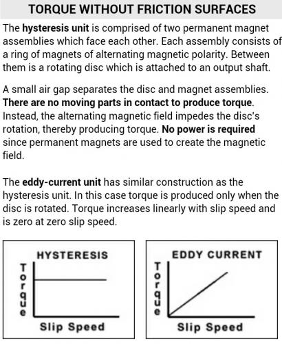
.
It seems like Hysteresis braking better fits the problem. With a flat torque curve you can implement a kind of "current limiting" that will protect the motor from overheating.
Add in the fact that the torque is applied through the throttle and you should be set.
The only losses I can see come from the difference between torque delivered verses torque applied and that loss shows up as "slip" and produces a small amount of heat. Using something like Silicon Steel and laminations should reduce eddy current losses. Laminated Silicon Steel typically produces less than 10 watts per kilogram of heat (often much less) so it should be small.
.
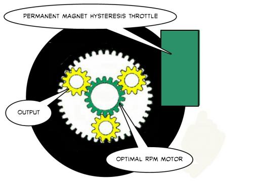
.
However, there's also an argument that some mixture of Hysteresis and Eddy Current techniques could achieve a better result.
.

.
With ebike controllers we typically distinquish between "battery side" and "motor side" current limiting and I think we are in a similiar situation. However, once you start to allow excessive currents into the motor you sort of reintroduce all the problems you were trying to fix.
If I were building one I'd use Hysteresis only... then consider testing other ideas afterwards.
.
Basically you are describing a standard mechanical clutch.
I think the question becomes one of output efficiency.
How much torque is transmitted to the output and how much heat is lost in the process?
For gasoline motors there is an expectation of having major losses in multiple areas, but the amount of power the gasoline motors create is so large that they tend to (until recently) not care much.
Also we might be talking about low torque levels with a Hysteresis type clutch. If the gasoline motor is producing 200 hp a Hysteresis type clutch might need to be too big and heavy to be practical.
With an ebike we care a great deal about efficiency and weight, so it needs to be proven which system is best. For 1000 watts of output we are not going to be happy if more than 25 watts of heat is lost through hysteresis. At 25 watts we are only talking about 2.5% loss.
* * * At low rpm for a motor with fixed gearing the losses are:
~ 400 watts to copper loss
~ 10 watts to hysteresis loss inside the motor
~ 40 watts to the chain / sprocket / gears
...overall efficiency becomes ~55%
* * * With this Hysteresis Planetary Gear motor the losses are:
~ 100 watts to copper loss (or less)
~ 35 watts to hysteresis loss inside the motor (higher rpm)
~ 40 watts to the chain / sprocket / gears
~ 25 watts to the hysteresis clutch
...overall efficiency becomes ~80%.
----------------
It's about a 25% reduction in "overall losses" at low rpm (like climbing a hill) but it's subtracting from copper loss which is the most dangerous for the small motors, so it's really addressing the most critical aspect of losses.
.
.
Truth always ends up being more complicated than you first expect.
Above is the Heat Dissipation equation for a Hysteresis Clutch.
On the left side (Pv) we have the actual heat in Watts that will be created by using this clutch. On the right on the bottom we have what seems like a strange constant of 9.55. What the heck is that you might say? Well, it's really just there to convert rpm values into radians per second, so you don't need to feel it's very mysterious.
Next we tackle the "slip" variable "s". If the clutch is rigidly clamped down so that no slip is taking place then no heat will be created. If there is no slipping going on then s=0. On the other extreme we might have a clutch that is not applying any torque at all and is "free spinning" which means that "slip" is at a maximum and s=1.
Things begin to get interesting as we apply some torque transfer into the system. In theory "slip" can be at it's maximum meaning the drive side is "free spinning", but it requires some power in the form of drag to maintain that speed. In such a case this is more like a brake.
Simplified we get:
Heat (Pv) = Torque (T) * Motor Rpm (ns)
...so for a given Torque the faster you run the motor the more linear heat you dissipate.
For a clutch things are a little different.
As we begin to actually transfer some rotation into the output side of the clutch our "slip" begins to decline. The relative rotational difference (ns) goes from 100% of the Motor Rpm (like with the brake) to an Output Rpm that is some amount less.
Here's where things begin to get weird...
A Hysteresis Clutch cannot be driven with heat to infinity. Like with an electric motor you have limits to how hard you can drive them and generally they must be kept cool and not driven harder than some value of Pv.
What this means is that what I was thinking in previous postings was overly simplistic. You can't so easily assume that a Hysteresis Clutch will deliver a simple heat dissipation.
The idea of have "current limiting" through use of the Hysteresis Clutch may have merit on the motor side, but now we have another issue to worry about which is the CLUTCH itself overheating. (didn't think of that)
---------------
So let's try some real numbers for the idea...
On the motor side let's say we started with 1000 watts of electrical power before we get to the motor. After losses the the motor delivers 90% efficiency (900 watts) at 6000 rpm. Using that 9.55 conversion (let's call it 10 for simplicity) we get:
6000 rpm / 10 = 600 radians per second.
Power = Torque * Radians per second
900 watts = Torque * 600 radians per second
So Torque = 1.5 Newtons
The planetary gear creates a 3-to-1 geardown...
Which means on the output side (the side where the clutch will be) the numbers become:
600 radians per second becomes 200 radians per second.
1.5 Newtons becomes 4.5 Newtons.
Now we have to "decide" how much heat the clutch will dissipate. Let's say we allow the clutch to dissipate a maximum of 100 watts of heat.
We then decide on the "slip" we will accept. This would be like our "throttle". Let's say we want our "slip" to be at 15%. So the value of ns will be:
200 radians per second at 85% is 170 radians per second and s=0.15
So:
100 watts = Torque * 170 radians per second * 0.15
Torque = 3.92 Newtons
Now we can know output power:
Power = Torque * Radians per second
Power = 3.92 Newtons * 170 Radians per second
Power = 667 watts
But we must substract our heat:
667 watts - 100 watts = 567 watts (yuck! 57% overall efficiency)
...so the overall efficiency comes out roughly equal to direct drive BUT the heat is now being generated primarily in the clutch rather than the motor.
Is it worth it? I'm not so sure... not the result I wanted. :(
Seems these Hysteresis Clutches create a lot more heat than I hoped.
For an RC motor that works best at optimal rpm I can see some benefit in that you can drive the motors with more speed and reduce bearing loads, but ultimately the clutch ends up being:
A GLORIFIED HEAT SINK !!!
.
Before ending the Hysteresis Clutch idea I need to go back to the D-Drive.
The "problem" has always been that when you try to implement some form of infinitely variable transmission you end up "fighting" one type of torque with another.
What makes the D-Drive so interesting is that the inputs are entirely independent of each other and that actually solves the problem.
The Hysteresis Clutch essentially "exposes" what the old problems were and doesn't really solve them.
...but what the heck, I gave it my best shot. ;)
-----------------
Hysteresis Clutch Performance (based on previously described planetary gear)
.
Assuming I got the math right... it looks like heat dissipation (left) is not too bad when the "slip" is fairly low. But as "slip" approaches 100% things get really ugly and heat rises exponentially.
The idea fails at low rpm... the very area it was supposed to fix.
.
Pages