
Hello all,
I recently purchased a Jan 2006 vintage E-Max Sport. After about 10 miles of good performance, I managed to break something by attempting a standing start up a grade while overloaded. I'm a reasonably good mechanic, but don't have much experience with AC motors and electronic controllers.
I have the shop manual, if it can be called that, it's abysmal. I'm interested in fixing my E-max, but I'm also interested in compiling or writing better troubleshooting documentation for other E-max users, as it's obviously needed. I'm also interested in some of the mods I've seen here, and willing to compile a single reference document for this info so it's a little more accessible.
Any tech help troubleshooting would be much appreciated, and shared with the E-Max community.
The symptoms:
Loud "knocking" sound from the hub motor on starting and cruising. Louder under high
load(starting underway).
In some positions (rolling back and forth), no motive power, just a "grinding" sound.
For both of the above symptoms, it feels a lot like a stripped gear tooth, although there
are of course no gears involved in the E-Max hub motor.
Fairly severe vibration when running under no load (up on center stand).
Reduced power (approx 1/2 - 2/3?).
The shop manual lists five possible causes for the symptom "The motor makes a loud noise":
Wheel bearing bad
Rotor grinds on cover
Loose magnet(s) in motor (manual calls this "alnico")
Motor cover is misaligned
Hall effect sensor defective
I pulled apart the motor, and am convinced that the problem is not due to any of the first four causes. I did find an old quality control sticker (!) riding around between the rotor and hub, but removing it didn't fix the problem.
The manual's troubleshooting technique for the Hall Effect sensor is less than illuminating, but from my tests with a voltmeter, it appears to be working. The "timing" could be off, don't have a good way to test that yet. The sensor wasn't loose or misaligned as far as I could tell.
I suspect that the trouble lies in the controller, probably one or more power transistors failed. I tried using the troubleshooting technique in the manual and did not get values in spec, which would confirm this. Caveat; some of those values are suspect, and the troubleshooting instructions are incomplete (sentence fragement at end of page).
I pulled the controller and opened it up, don't see or smell anything burnt. The 1000uf Capacitor #101 does have a large dent in it, but that looks like something that must have happened during or prior to installation.
This is a "new" style controller with the large 5-pin threaded collar and E-Max badge.
Here are the volt/amp/ohm readings I collected from the controller:
Voltmeter:
Black/Red - 50.0 volts
Yellow/Green/Blue - varies with position of motor, appears to be at regular intervals throughout 360 rotation.
Ohmmeter:
Black/Red - unstable readings. Starts at about 4.6 ohms, drops down past 1.0
Black/Yellow - open
Black/Green - open
Black/Blue - open
Ammeter
Yellow - 2.18
Green - 3.05
Blue - 4.88
These readings indicate a fault in the controller. Although I have opened the controller, I don't have a good plan to test individual components, so any specific help here would be much appreciated.
One more piece of probably unrelated information. Although I never tested it fully, Joe told me the one or more of the batteries were suspect and that this scooter had limited range. This problem appears to be distinct from the current "shuddering" and "knocking" problem as i did not have any problems for the first 10 miles of operation.
Guineng Battery voltages range from 12.60 to 12.89.
Odometer reads ~350, and the overall condition of the scooter conforms with this; it's in good shape and everything else works fine.
Anyone with troubleshooting tips and/or known good circuit specs - voltages and amps, your help is much appreciated. Like I said, I'll take the time to write them up and re-post a comprehensive troubleshooting guide for everyone's benefit.
Thanks,
Chris


Just some random comments/questions for tour consideration:
By "no motive power when rolling back and forth" what do you mean? Do you mean a "dead spot" in teh moor rotation where it is producing no torque? Also, is there a physical metal-on metal grinding sound?
It seems that the apparent amps for each motor phase should be the same (and should be AC amps by the way - a DC brushless motor can be regarded as a sort of AC motor), and should vary with the throttle setting. So, I'm not sure what you were measuring here.
The resistance between the red and black leads and the red and various phase leads should be a higher than the what you reported and should normally increase as the meter charges up the filter capacitors.
The large dent (i assume you mean a dent and not a bulge) in one of the capacitors is not good. If the capacitor is shorted one of the motor phases will be shorted. This will cause the motor to be partially plug-braking with a distinct resistance to turning the motor. This capacitor should be replaced.
The FETS are east to check with your multimeter on "diode check" - what the manual calls "through current". They are checked just like a NPN transistor, google for a procedure. I believe the manual had a fairy clear procedure testing them all together via the five leads.
I assume you checked continuity/resistance of the motor phase wires.
Did you charge the battery pack? The batteries seem to be at a low state of charge. Their open-circuit voltage should be about 13.5 or so when fully charged.
A stumbling and "stuttering" under load is the normal behavior of the controller's low voltage cutoff when the battery pack is depleted to the point of sagging to about 35 volts under load.
As far as repairing the e-max controller, with the programmable Kelly controllers for brushless motors that are now available for a reasonable price, I would not bother putting too much time, money or headaches into fixing the e-max controller. Replace it with a Kelly controller.
You symptoms are the same as mine.
ScooterTech (usatracy) posted a testing method for the hal sensors on the VoltsRider forum
http://www.voltsrider.net/vr/forum_posts.asp?TID=67
EVT thinks it is the controller, but I'm betting on the hal sensors.
I'll let you know what I find.
I have done the same thing - brokedown because of oveload. My son was standing still in a small hole and was trying to get up using full gas. Bad idea.
I have been working on it for some weeks now and it is the controller. I have a swedish home page that describes a lot of the procedure. THere are some images there that you might find useful but the text is in swedish. (www.ragnemalm.se/bengt, click on elektronik/e-max).
The fuses was broken
Two of the MOSFET's was broken
SOME circuit of the first MOSFET driver is broken.
The fuses and MOSFET's was secondary problem, the actual problem lies in the driving circuit. I can understand why it broke but it is some circuit before the MOSFET driver, TA110, not the driving circuit itself. To find out problem in driving circuits, measure on the gate to the transistors and turn whe wheel (by hand). I have disconnected the motor during the tests.
The error will lead to that both high side and low side of the transistors is turned on at the same time resulting in a short circuit.
The hall can be checked by measuring on the three return wires an turning the wheel. You should have a square wave. Power to the hall should be 6V. If you have 6 V when also the DC/DC-converter that sources 12-15 V to the controller circuits works. For any problem there, I have a schematics on my home page.
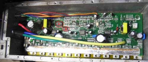
In my controller (the first version) all circuits are scaped so I know have problem finding out two circuits. Maybe someone can help med there? It is around the hall circuits, see the picture, circuit A and B.
Bengt,
Your controller board is revised considerably from the original e-max controller. (where's the third, large filter capacitor for the yellow phase?).
But the left part of the board does look similar to mine.
Thankfully, I have a controller which they didn't scrape the numbers off.
The IC that occupies the position "A" (on my board it's U4) is a Motorola MC33033DW brushless motor controller. It has 20 pins.
The IC at Position B (U9 on my board) is a HEF4069UBT hex inverter.
Hope this helps.
Thanks!
I was able to see that "A" (U4) was a Motorola part but not the number. I guessed that "B" was an inverter or a buffer but there are a lot of versions so that helps.
Regarding the filter capacitor, actually it is the "black phase" that is missing, it is shared with the input capacitor). Voltage is 63V, I think that is a little low as thge spikes could be larger, espcially as they use very low ohm resistors to the gates. I have an application note to the driver circuit that have recommandations to the gate resistor values. But the values should depent on the gate capacitanse so it would depend on the transistor.
Now I have full information about most of the driver circuit. I still miss the three eight pin circuits right of the circuits I mentioned but I do not think there are any problem there but it could be good to have for the future. (The first of the four is not scraped).
A big difference to future versions is that my have an unused DC/DC converter to the right. It is the yellow transformer and a transistor on the back.
Did you mean Blue? In order to run my e-max at 60 volts, I upgraded all the 63v 1000 uF filter capacitors to 100 volt. The fit was a bit tight, but do-able. One controller has about 9000 km of use without trouble.
Of three controllers I've owned one failed due to the large capacitor leads breaking from shaking. It was repaired and is running. Another controller failed similar to yours - something apparently caused the FETs for + and - commutation of the blue phase to close simultaneously causing a short. It happened right after doing the capacitor upgrade plus modifying the shunt resistors for higher current operation. This requires grinding recesses in the cover of the small-case used in earlier versions, so I attributed the failure to carelessness - stray metal or solder somewhere.
My version uses different FETS - IRFP2907 (TO-247 package). They have plenty of drain current capacity (180 amp continuous for each parallel pair) for adjusting the current limit upwards. I need 90-100 amps to get satisfactory hill climbing performance.
I bought replacement FETS, motor controller and gate drivers but never tried to replace the IC components as I really don't have the SMD soldering equipment and skills.
Please update us if you get the controller running.
Yesterday I finally succeeded to repair the controller!
First of all - note that all I write here are related to the first version of the controller but most should be the same for later versions as well.
Basically it was some MOSFETS + two of the MOSFET drivers that was damaged. If anyone have similar problems and want to try a quick and dirty repair, replace all of the damaged FETS (check for short circuit and 0.5V reverse diode) and also replace all drivers.
For those who want to go a little bit further you can continue with this. If the controller was damaged from overload as my was two or more of the MOSFETS will have been destroyed and the input fuses will have blown. If this is the case I can recommend the following procedure:
- The glue (heat melting type) that is used to the capacitors is agressive. Remove all and replace with non-agressive electronic silicone.
- Check all resistors to the MOSFET gates. Should be three 51 ohm in parallell. Measure with a ohm meter that the resistance is ~17 ohm.
- Replace all damaged MOSFETs. Check for short circuit and that the reverse diode of 0.5V is still there.
- If you do not have a power supply that can output at least 20V or a scope, replace all of the MOSFET drivers. It may not be sufficient to only replace the driver at the damaged MOSFETs. In fact, it may be some of the other drivers that are damaged.
- There are different types of MOSFETs in the controller. If it is a TO-220 that have a non isolated package, measure that the high side MOSFETs are not shorted to the box. (The low side are already grounded).
- If you have a power supply, feed the + line with 20-50V after the fuses with the power supply. (Note that the wheel must go free). Set the current limit very low, about 100 mA. Turn on power and check the current. Turn the wheel manually and check if the current changes. In case of high current just feel with your finger on the drivers and replce anyone that goes hot. Replace until there is no high current in this situation. End with trying to give some gas. The wheel should turn.
- If you have a scope yopu can measure on the gates at the same time as you do the above. The low side MOSFETs should have a square wave and the high side a square wave that is Pulse Width Modulated depending on the gas level.
- Finally put back new fuses (2x30A). Glas fuses can be hard to find and are tricky to solder. Replace with ceramic types from Little Fuse. See Farnell 151-0911.
- I replaced all 63V capacitors with 100V type to get better margins. It will be tight but possible to fit them in the box.
I think the reason that the drivers are damaged in case of overload are that at the time of break down the engine will put a large negative transient to the Vs pin of the driver. I have put an extra power diode from GND to Vs pin that may avoid this in the future. Normally this diode are already there as the reverse diode in the MOSFETs but if they are blown...
On http://www.ragnemalm.se/bengt you can find some schematics, images and more descriptions but all are in Swedish. I hope this will finally help many people that have damaged controllers.
Have a nice silent drive with your e-max!
/edit: The part on my homepage that are about the controller are now in english!!
Hello,
today I killed my controller again.
Now I want to use another one to win time for working on the original one.
I tought of a KELLY (Model KEB48220 100A 48V 2.2KW).
You think this would be the right one?
I still have no reaction from Kelly about the shipping to germany.
Are there any other suppliers?
All the China-Controllers only seem to make 1000W.
Best regards from Germany!
Michael