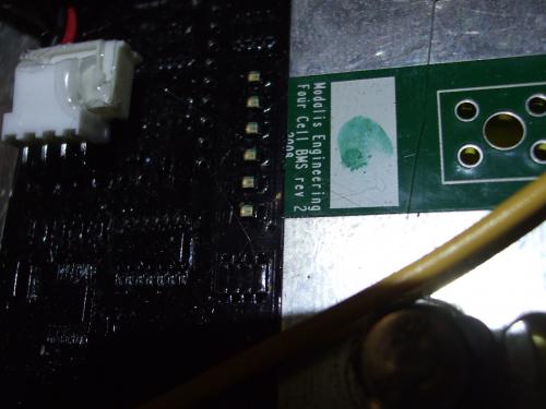
Photos of the innards of a Native Z6 Lithium electric scooter which isn't charging
Submitted by GreenBiker on Thu, 09/02/2010 - 21:50
- GreenBiker's blog
- Log in or register to post comments

Who's online
There are currently 0 users online.
Who's new
- eric01
- Norberto
- sarim
- Edd
- OlaOst
Support V is for Voltage

Comments
Re: Photos of the innards of a Native Z6 Lithium electric ...
Re: Photos of the innards of a Native Z6 Lithium electric ...
Re: Photos of the innards of a Native Z6 Lithium electric ...
Re: Photos of the innards of a Native Z6 Lithium electric ...
Re: Photos of the innards of a Native Z6 Lithium electric ...
hmm,
not familiar with that BMS.
having a look at it, it looks like it has one master module, and a few slaves, each connected to 4 cells a piece.
not a bad design as it gives 12v to each board.
pretty cool how the BMS boards also form the battery interconnects :D
since you now have access to all the cells, what are the voltages on each cell?
Matt
Daily Ride:
2007 Vectrix, modified with 42 x Thundersky 60Ah in July 2010. Done 194'000km
Re: Photos of the innards of a Native Z6 Lithium electric ...
Having another look.....it looks like the BMS has flexed.
unless the cells are *very* well strapped together, the cells move around relative to each other.
the BMS being bolted to multiple cells is rigidly connected.
I suspect one or more of the BMS module has developed a hairline fracture, causing it to fail.
I suspect it to be a design flaw in the BMS.
have EMS replied at all?
Matt
Daily Ride:
2007 Vectrix, modified with 42 x Thundersky 60Ah in July 2010. Done 194'000km
Re: Photos of the innards of a Native Z6 Lithium electric ...
Hello Matt,
The BMS has broken down in respect to the 5V signal to the battery charger's cobbled-on relay, as stated on the forums.
EMS says that the BMS should continue shunting/balancing the cells, and indeed, that does seem to be happening.
The BMS seems to be balancing the cells, as the voltages (see postings on the forums) as exactly the same on all 16 cells to within 3 decimals.
The present problem is charging the battery without overcooking the cells, as the EMS charger is a 68V (nominal) charger which puts out around 90V actual, and the scooter needs around 60V only. So, I'm thinking of just using a power supply for topping up the scooter batteries and using the 68V charger with a timer.
Re: Photos of the innards of a Native Z6 Lithium electric ...
Impressive design...
Re: Photos of the innards of a Native Z6 Lithium electric ...
BMS does not have any flex or fractures. Those lines look to be some left over threads of hot glue.
This vehicle was a sample vehicle sent to Canada for evaluation. The BMS is from the GPR-S. It was not really designed for the scooter because it requires an on board charger and there was not enough room on this unit to place it. Had to put the charger and Solid State Relay (SSR) in the trunk case which was not ideal. This unit was not meant for resale but more for Canadian DOT evaluation.
There was one other Z6 unit with a SSR BMS like this one that was used as an Olympic Cycling Center training vehicle.
All other Z-6 lithium models had the standard multi-battery wires to a remote BMS board. The key advantage to this BMS is no spaghetti of wires. The boards also data log which is a nice feature. We have tried dozens of BMS. In concept li Battery management systems are simple but in practice they can be complex and not at all trivial.
To see if all the BMS boards are communicating either a laptop needs to be used with the interface or all boards have to be visible to see the sequence of lights flashing in series. The boards will however operate stand alone with out communication with one another. Meaning they will still attempt to shunt however if the SSR is jumper-ed the charger cut off will be disabled. You can charge with the SSR jumper-ed however it would be a good idea to use a lower voltage charger as I think Matt had suggested.
TK