YAVLiC - Fitting the Li battery 2
Submitted by manfred.bartz on Sun, 08/18/2013 - 04:28
I am trying to figure out how to fit the battery. The original plan was to put 32 cells arranged as 2 rows of 16 in the bottom of the battery compartment. However, they don't fit.
At the rear, welding lugs from the frame's rear casting are protruding. I am prepared to grind some of that away to make the cells fit side by side.
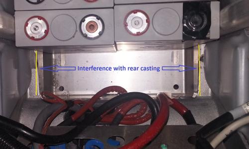
The interference at the front is more problematic:
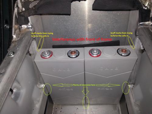
I am not going to attack the frame with a big hammer or a hydraulic jack and I won't grind away material from the frame's tubing.
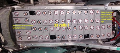
Well, adversity is the mother of all innovation... So now I will be able to fit 33 cells instead of 32! See:
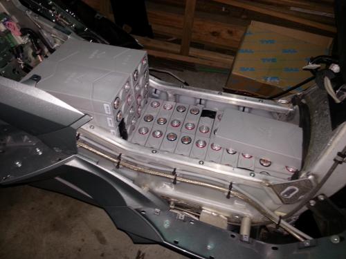
The whole pack will probably be arranged like this:
Topics:
- manfred.bartz's blog
- Log in or register to post comments
Who's online
There are currently 0 users online.
Who's new
- eric01
- Norberto
- sarim
- Edd
- OlaOst
Support V is for Voltage

Comments
Re: YAVLiC - Fitting the Li battery 2
I have heard that placing the batteries in a position with their broad face parallel to ground is NOT good, as circulation of electrolyte between the plates is impeded. It is better to place the NARROW side down, if not installing them in the normal, "terminals up" position, to allow better flow of electrolyte between the plates, by internal wicking action.Grinding of the internal welds of the VECTRIX battery box is a normal procedure when installing a larger lithium pack, be sure to remove all metal particles!
Robert M. Curry
Re: YAVLiC - Fitting the Li battery 2
You had me worried there for a while but all I can find about cell orientation is either nothing (vast majority of datasheets) or that it does not matter.
The other problem is that laying some of the cells flat as shown in my photo is the only way they can be made to fit under the existing fairing. Even then, the existing battery cover will have to be cut up and be partially replaced with something else – an aluminium cover I think.
It would be possible to stand cells up in a top layer but for that, I'd have to convert the scooter to a motorbike and fit a "tank". I actually would not mind doing that but I am not good at making complex 3D parts such as a motorbike tank ...
Edit 2013.09.01: ev-tv.me has some useful information about CALB CAxxFi cells including about cell orientation. According to that information, the cell vent must never face down. The manufacturer's recommendations are to mount cells with the vent up or if that is not possible, in horizontal position on narrow edge. I.e. not flat side down. The cited article further says that "We have yet to receive a cogent explanation of why horizontal mounting would cause any decrease in battery life or capacity. All such explanations we have found on the Internet are demonstrably nonsense".
Re: YAVLiC - Fitting the Li battery 2
I happened to have more 66Ah cells on hand so were able to take some pictures of how things fit
Manfred putting 5 cells in side ways in the bottom row prompted me to have another look at the bottom layer - putting 5 sideways hadn't occured to me earlier
I discovered that if you put the 5 cells in sideways at the motorcontroller end, you don't need to grind any material away to make the cells fit.
I didn't wire any of the cells up - I had to box them back up again to ship out on Monday
If you start with the positive terminal next to the MC in the bottom layer, and have the final negative terminal in the top layer, there's enough room under the seat for the shunt for the cycle analyst
I had to cut away the front of the fan cover for those 4 cells at the front to fit, but the top fairing cover still keeps the water out
Matt
Daily Ride:
2007 Vectrix, modified with 42 x Thundersky 60Ah in July 2010. Done 194'000km