A forum to collaboratively and openly develop repair, improvement and maintenance procedures for Vectrix Maxi Scooters.
This forum / thread is not a Vectrix manual yet.
It will possibly contain untested, speculative materials and potentially dangerous errors.
This is part 3 - due to the many photos a single thread takes longer and longer to view, so I have to start over every now and then.
I will try to provide thumbnails and links to higher resolution pictures, if needed, to keep the download size lower this time.
See http://visforvoltage.org/forum/3635-vectux-part-2-open-source-vectrix for the immediate lead up to this thread.
Mr. Mik


Today I opened up the battery compartment and checked the motor cable connectors with a mirror - without removing the battery: All looking good so far!
Whilst I was at it, I installed a 100mA fuse in each of the two cables from the motor controller to the RETAMPI, just in case... Everything needs to be fixed down with cable ties on the lower half of the motor controller cover, or the battery housing cover will not fit back on.
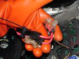
http://s281.photobucket.com/albums/kk217/Mr_Mik/Vectux/RETAMPI/?action=view¤t=DSC04827.jpg
Using Ohm's law I calculated that 418MΩ resistance would be needed in series with the RETAMPI to drop the voltage from 4.38Vmax to 100mVmax.
Time to practice my soldering...
http://s281.photobucket.com/albums/kk217/Mr_Mik/Vectux/RETAMPI/?action=view¤t=DSC04834.jpg
In the Real World, after many test drives, I ended up using 40*10MΩ resistors and a 2MΩ variable resistor (Pot(entiometer)).
The idea behind putting in a 2MΩ Pot was to be able to fine-adjust the RETAMPI to "100".
But the Pot was probably a waste of time (except that I learned lots today! LOTS! Stuff I knew, or so I thought...
And then it was Hot Glue time again:

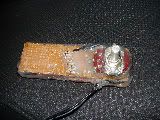
http://s281.photobucket.com/albums/kk217/Mr_Mik/Vectux/RETAMPI/?action=view¤t=DSC04855.jpg
After an all day effort the RETAMPI (Real Time Amp Indicator) is now calibrated to show the percentage of the maximum possible power draw. The hot glue cover on the RETAMPI proved to be a good choice so far: I was able to melt it away from the jumpers (for voltage and decimal point) and re-solder as needed (set to 2V range, no decimal point, although 200mV should have been the appropriate choice, but it did not work.) Then I closed the gaps again with more hot glue.


http://s281.photobucket.com/albums/kk217/Mr_Mik/Vectux/RETAMPI/?action=view¤t=DSC04840.jpg
http://s281.photobucket.com/albums/kk217/Mr_Mik/Vectux/RETAMPI/?action=view¤t=DSC04836.jpg
The meaning of the numbers on the RETAMPI display is:
"-50" means that half of the maximum possible current is being drawn out; "-100" means full amps leaving the battery; "66" means 2/3 of the max current are being put back in by regen braking, etc. etc.
Here is a video of the RETAMPI during acceleration and deceleration on relatively flat ground:
Mr. Mik
This information may be used entirely at your own risk.
There is always a way if there is no other way!
Could someone explain how I can make a safe voltage indicator for the Vectux dash?
I would like to keep all wiring that could become "live" (with the up to 150V of the battery) inside the secure battery compartment, and "export" only safe Voltages and currents out of there, even in a severe crash.
Ideally I would like to connect several groups of the 102 cells so I can get readings that indicate if/when a cell in these groups starts to fail = drop voltage under load more than the others.
And I would like a display of the real time voltage of the whole battery to serve as a "fuel gauge".
Mr. Mik
This information may be used entirely at your own risk.
There is always a way if there is no other way!
Easy, if you're up for a little soldering.
Get a cheap $3 DVM. Take it apart and desolder the screen. Then it's just a matter of semi-permanently hooking up the probes and extending the screen's wires up to the dash.
Since basic DVMs are so cheap, you could do this with multiple groups of batteries, but that's a lot of rewiring to do. :/
BTW, voltage on a NiMH/NiCd/lithium pack is a terrible indicator of SOC, especially on high quality cells. A123s hold their voltage so well throughout their discharge curve that it's been said that it feels like something suddenly has blown when they go dead.
The author of this post isn't responsible for any injury, disability or dismemberment, death, financial loss, illness, addiction, hereditary disease, or any other undesirable consequence or general misfortune resulting from use of the "information" contai
Thanks, LinkofHyrule, good idea using a dismantled voltmeter! That could work for the "whole battery" voltage display.
Some Vectux battery facts and calculations:
102 cells (54 + 48), Ni-MH.
Only two cables go into the battery: Positive and Negative lead, there is no cabling to individual cells.
There are 12 battery temperature sensors spread through the cells.
The battery voltage gets displayed only during charging.
Max voltage seen by me: 151V (whilst repeatedly charging in CP/tr/CP/tr/CP... etc mode after fuse replacement; battery indicator erroneously showing not full.)
Lowest voltage seen by me: 108V (wheel barely turning when on the rock, totally empty, unrideable long before that)
Usual range:
125V - 141V - 147V
125V - reduced power, ? fuse damage when going up steep hills?
128V - battery empty, just enough left to have full power available.
141V - resting voltage 24hrs after full charge
147V - at end of charging.
147/102 = 1.44V per cell at end of charging
141/102 = 1.38V per cell full resting charge
128/102 = 1.25V per cell just before "reserve" gets used with loss of full power
125/102 = 1.22V per cell when empty
So basically, the individual cells fluctuate between 1.38V when full, and 1.25V when almost empty. The BMS prevents further use of the motor gradually when the voltage hits about 125V, reaching an absolute cutoff at 108V.
There are three subsets of cells that could be measured without even taking the cell clusters apart: 27 cells x 2 in the rear battery and 48 cells in the front battery.
But if I decide to do the "battery rework" (as per recall), I could break it up into multiple smaller sub-sets.
The question is: How low is the voltage of a "cell going bad" going to be?
Or in other words: How big can I make the groups without risking missing it when a cell goes bad?
Groups of three cells? That makes 34 sets of wiring....
Groups of three is the only way to break the packs into even sized chunks so the measured voltages can be directly compared.
I would need sixteen 3-way switches and one 2-way switch for that...that switchboard would definitely not be something to be operated whilst riding!
Maybe I could build something that automatically switches between the sub-sets and logs the voltages electronically?
Another option might be groups of 9 cells x 6 for the rear battery, and 8 cells x 6 for the front battery. That would split it into the "chunks" that need to be re-connected differently for the battery rework (thats an educated guess only - I need to see what the actual dismantling process for the batteries turns out to be, to be sure).
If anyone has observed the actual battery rework - please let me know how it was done!
Negative battery terminal (Temp sensor cable removed):
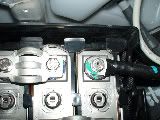
Click here for a high resolution picture
The positive battery terminal:
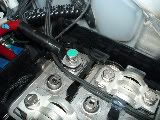
Click here for a high resolution picture
Front battery:
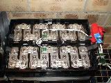
Click here for a high resolution picture
Rear battery:
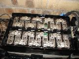
Click here for a high resolution picture
Both batteries:

Click here for a high resolution picture
Note that the temperature sensor cables remain attached and are removed from the frame together with the battery.
Mr. Mik
This information may be used entirely at your own risk.
There is always a way if there is no other way!
Could this setup work for the voltmeter from the whole Vectux battery to the dashboard?
I hope to switch the ReTAmpI from amps to voltage as needed.
Mr. Mik
This information may be used entirely at your own risk.
There is always a way if there is no other way!
The Vectux is down again, waiting for tow truck...
Main fuse blew whilst coasting!
This could mean a number of things:
A) The fuse was not new and had been damaged during the battery conditioning process whilst it was inside the Vectrix from which it was removed. The fuses might be damaged before the scooters even get to the dealers, or by dealers conditioning the batteries before delivery to the customers.
B) There might be a batch of faulty fuses around.
C) A higher rated fuse might be needed, 150A instead of 125A.
I'll try to source a 125A NEW Littelfuse; if that blows as well, then battery conditioning procedures (with under-voltages)are not the cause of the failures.
Still waiting for the tow truck...
Mr. Mik
This information may be used entirely at your own risk.
There is always a way if there is no other way!
I placed several requests for quotes etc with distributors in Australia and Singapore for a Littelfuse L25S 125 and am waiting for replies.
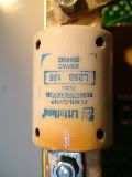
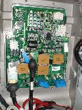
Click here for a high resolution picture
This fuse looks to me like it was removed from a scooter that had had the battery cable smoldering, and then it was put into my scooter.
Note the discoloration just above where the positive battery cable connects. That is just a guess, though...
I placed an order for a fuse that is apparently a fuse made to replace the Littelfuse L25S 125, with this fuse specialist:
SWE Check
I am not sure what the actual manufacturers name is, either Bussman or Edison:
The fuse is called E25S 125
Including postage and GST about AU$ 95.-
They anticipate a wait of 4 weeks for this fuse.
I have placed more requests for quotes/availability for this replacement fuse with other Australian distributors of Bussman fuses, hoping that I can get one sooner than 4 weeks away. It would be good to have a spare, anyway! The originals have lasted an average of 1500km.....
If I can get a new Littelfuse L25S 125 before the ordered E25S 125 turns up, then I'll put that into the Vectux and keep the other one as a spare.
In the meantime I might take the gearbox apart and get Nylon planetary gears made; but only if the downtime is likely going to be more than one week.
Mr. Mik
This information may be used entirely at your own risk.
There is always a way if there is no other way!
Here are more potential fuse alternatives to the original Littelfuse L25S125 for the Vectrix:
E25S(Amp); FWX(Amp)A; A25X(Amp) - 4; XL25X(Amp); RFN(Amp); SF25X(Amp).
Look here for details.
Mr. Mik
This information may be used entirely at your own risk.
There is always a way if there is no other way!
So you want to let manufacture nylon planetary gears for your vectrix? Hope you know what you are doing...
I'd be interested in your opinion about the faisability of putting an additional little battery pack in the trunk under the rear seat. Would the board electronic be able to deal with the additional voltage (I'm thinking about a pack of the same Amp of the original put in serie, voltage t.b.d.)?
I know exactly what I am doing - I am learning!
And: "I know that I know nothing!"
Today I learned that my assessment of the gears was correct:
I took the planetary gears and the ring gear to a gear and engineering workshop.
The old hand there measured the gears and found that the two noisier planetary gears were in fact 1/1000 of an inch larger than the good, quiet one.
And he also confirmed that the ring gear is slightly oval: 0.1mm difference with a quick measurement. I had found up to 0.18mm difference earlier.
He advised me to have the ring gear re-maćhined rather than making nylon planetary gears to start with.
AU$250.- for the machining, and several weeks wait because the machine is currently doing a run of other work.
He believes that the noise will not get worse over time if I do nothing. It might even get better because the ring gear is made from softer metal than the panetary gears and the narrow spot might wear down.
Regarding add-on batteries: NO WAY! Totally unsafe with these sort of voltages. The only other way I can see at the moment would be to replace the batteries inside the safe, low COG compartment with better batteries. But before that would work well, full access to the CanBus and the higher level programming of the scooter (charger etc) would be needed.
What could be done immediately is add a trailer with a true sine wave 2kW generator in it! But without full control of the software it could only be run when the scooter is parked. It would probably be unsafe to have a 2kW generator running whilst driving, anyway.
Always imagine yourself lying stuck under 230kg of damaged scooter in a puddle before considering any mods!
Although it appears idiotic at first that the main fuse can only be replaced with hours of work, it becomes clearer after doing the job a few times that this is for safety reasons.
The power of a battery pack this size needs to be contained well, in case of accidents and/or careless intentional access to live parts.
Mr. Mik
This information may be used entirely at your own risk.
There is always a way if there is no other way!
The Vectux is up and running again! (At least up...running tomorrow morning!)
I managed to get a fuse a lot faster than expected. But not the original Littelfuse - they have unfortunately not managed to answer any of my emails yet, and there are no characteristic curves published that I could find, and a lot of competition....It's a Bussman FWX fuse. The previously ordered Bussman FWX 125A fuse is still being manufactured for me (along with two more, they make them to order!) somewhere (?Mexico?) and should arrive in 4 weeks; then I'll have a spare!
Top marks for SWE Check !!!
Whilst other companies representatives were sounding annoyed when I asked them if they could check the availability of the 5 or 6 alternative fuses, the guy on the phone there had already checked before I asked him to! The fuse ordered yesterday arrived today - 2000km traveled overnight, but he did not even promise it would be here in 2 days time... Thats service! I know where I'll try to get my fuses from in the future!
Today I finally tried my original setup for the bridging cable between the two battery cell clusters. Using 2460Ω to slow down the charging up of the capacitors (and who knows what else) in there. It worked the way I expected, starting with about 60mA and dropping over roughly 30s to a steady 7mA. But the current builds up quite quickly again, the battery cables need to be connected quickly or the whole exercise is futile. All it does is prevent arcing at the battery connectors between the two cell cluster packs. (I do not want to call them "Batteries", because they are configured different than traditional batteries). But I might well be wrong about this. I'll use 2400Ω again next time, though! Previous attempts with an 8MΩ resistor and a variable resistor failed to work the way I expected.
I put the gear box back together again, too. Refilled with the same mix as last time.
A problem now is that the battery display on the right shows empty when the battery is in fact full. The same thing happened last time when the Vectrix tech changed the fuse, but then the battery had been 3/4 empty to start with. This time it is 95% full, but the Vectux believes it is empty.

Click here for a high resolution picture
So tomorrow morning I'll take off to work with 5km range, 2/17 in the battery - and I'll make it there and back, 40km! They could turn that into an ad....

But unfortunately it's just the display being out of sync with the real charge state of the battery. With a bit of luck this will reset the "Zero charge level" for the Vectux display, so that I do not have to equate 5/17 bars with empty any more....
Click here for a high resolution picture
Anyways, that's the sort of problem that needs access to the Vectrix software or at least the CanBus. I know from previous experience that the battery charge display on the right can be safely ignored when the known facts contradict it.
The motor power cable connectors all look very good, still, no signs whatsoever of any new heat damage. I think that's fixed!
And so should the fuse be, now....
A hopeful Mr. Mik
This information may be used entirely at your own risk.
There is always a way if there is no other way!
Hey Mik,
well you certainly are one of a true tireless tinkerer....man, I can't believe that Vectrix isn't volunteering to help you out.
They owe you schematics, software, support, even if it's not via this forum.
I for one would be nervous, honestly to have a fuse blow that often. Whenever I had that happen in electronics, it told me something was runner far hotter than it was designed to.
Looking at the severely discolored fuses (from not only your machine), I am really concerned that they have shot themselves in the foot and aren't up to admitting it.
Kudos for your pro-activity and I hope you can keep this baby on the road for as long as humanly possible.!
Peace out
GC
I'm sure there are many very fine people in that company that would help out if they could.
But the problem might be that they are bound by non-disclosure agreements, which are probably standard within a publicly listed company.
My impression is that even the Vectrix technicians have a hard time getting answers out of the tech department!
But that's not my problem any more and I sure feel a lot better for it!
2 days "down" this time due to the blown fuse instead of 25 last time, and 22 the first time is not so bad!
Fixing this interesting piece of technology yourself beats waiting for someone else to do it, anytime!
And this time it's a NEW fuse that will hopefully last for the life of the Vectux.
Mr. Mik
This information may be used entirely at your own risk.
There is always a way if there is no other way!
The battery ćharge indicator was showing 0/17th and the EST Range "0" for almost the entire trip to work (20km).
Otherwise the performance of the Vectux was FLAWLESS!!!
The uneven noise is gone! I might have become biased due to the time and money invested, but honestly, I could not hear it most of the time!
I got a strong feeling that from now on this bike will be reliable.
My colleages think I am deluded and want to know what pills I'm on, though....
So that's what it's supposed to be like riding a Vectrix...very nice indeed!
As to for the reason it is quieter now: I am not sure (apart from "God helps those who help themselves", that is!!).
It could be that the mounting pins for the ring gear are not perfectly symmetrically placed on the gear box housing and that I put the ring gear in 180deg different to last time, cancelling out the oval shape to some degree.It is impossible to mount the ring gear with opposite face towards the motor, but it can be rotated 180deg in the plane of the wheels spin.
If it was shaped perfectly it would not matter in which of these 2 positions it is mounted.
I'll have to make another video of drive-by noise levels as a reality check!
Mr. Mik
This information may be used entirely at your own risk.
There is always a way if there is no other way!
Mr. Mik
I have been silently reading, and enjoying, I think I might have a small bit of help...
During my intitial service, after new software, the tech said that I should do a full discharge to reset the battery, he warned that it my be out of sync until that is done.
I did the full discharge even though I noticed no problems. To do this he said to discharge the battery past zero bars, until the red battery light comes on for 5 seconds. He said at this point the battery (and BMS?) reset itself.
Have you pulled out 'the rock' and done a true full discharge?
I also wanted to comment about your unusual battery characteristics, mentioned in the Vectrix break in board. Even under hard riding I do not notice a moderate performance reduction until say 2-3 bars. Tops speeds stay well into the 50s or 60s MPH until about 1 bar.
But we'll see how my new battery performs ***next week*** (fingers crossed & biting lip ;) )
Thanks, Tangentstar!
The battery/display has never been set or adjusted properly on my second Vectrix, now the "Vectux".
Initially the battery showed 13 or 14 out of 17 bars full when the scooter would in fact not move any longer, and the battery symbol and buSVLt were on.
It was impossible to discharge it "past zero bars"!!!
I had to put it on the rock to slowly chop away at it until it got to zero, several discharges later.
A few hundred km later the fuse blew, and after it was replaced I did not repeat the procedure, because I was told that it might damage the fuse to discharge too deeply.
The "full" point of the display was incorrect after the fuse blew: The battery was somehow declared empty by the electronics, even though it was not empty. And the charger kept trying to get the display to show full, increasing the voltage to 151V repeatedly and heating up the battery.
It is doing the same thing again now, but worse because the battery was almost full when it was "declared empty" due to the fuse blowing.
Interestingly, removing the battery and the entire motor controller for longer periods did not cause this effect; the battery display was showing a plausible amount of charge, not zero, despite up to a week without batteries or motor controller board!
I rode 40km today with zero range and zero/17th on the display!
I just stopped the recharging process after almost 3 hrs, because it has reached 151V several times and because I fear it could cause damage to the battery. It will right itself gradually over the next 1-2 recharges. Yesterday it showed 2/17 bars when full, today 14/17 bars when full. One more recharge and it will be OK again.
If the "zero" point will be set properly remains to be seen.
Today I rode around a bit longer after returning home until the battery symbol came on and buSVLt was shown. It stayed on for about 10sec although I eased off the throttle immediately. I was trying to accelerate to 60km/h on a mild downhill slope at the time.
The RETAMPI showed that despite the lowish voltage of the battery the current draw was no higher than 33% up the driveway. I believe now that if low voltage and high torque have anything to do with the fuse failures, then the damage is more likely happening on the hilly road leading home; at 60-80km/h uphill the current draw can approach 100%; I have not yet tried this with a flat battery and the RETAMPI running.
Due to the low speed up the driveway the current drawn is much lower.
Mr. Mik
This information may be used entirely at your own risk.
There is always a way if there is no other way!
I did make a video, and biased me finds the noise much improved, even in the video!
The low speed vibrations are also gone, I think.
Only the 30km/h parts are included in the video, because that's when the noise is the loudest. I can only hear a touch of it at that speed now, at higher or lower speeds it is quieter and very even.
Still not "Negligible" as in the hype, but acceptable. I will be able to listen to podcasts at speeds below 60km/h now, and above if I get a windscreen extension.
And I remembered something else I did yesterday that might after all have something to do with the improved noise level.
Foxes and other sensitive creatures should cover their eyes again....
 This one is good!
The thing that might have done it is.....
The EAGLE: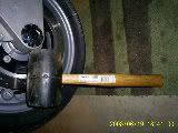 One of my favorite tools! Click here for a high resolution picture
I carefully measured the longer and shorter diameter of the ring gear again before reinstalling it into the Vectux yesterday. I marked where the longer diameter is, then placed the ring gear onto the carpet on concrete floor, and hit it with the mallet once. Then measured again, no change. Then hit it twice, measured, hit it thrice, measured, hit it four times, measured, hit it five times, measured - and gave up. 15 measured whacks all up....I thought it had not done anything, and that might be correct. I did not dare whack it any harder, in case it bends too much, or shatters.
Here is a remake of an earlier noise level video including the "After Eagle" recordings made today:
Remember, the "Before Eagle" noise levels in this video had already been markedly improved from the original state by shuffling the planetary gears to optimal positions inside the gear box.
Mr. Mik
This information may be used entirely at your own risk.
There is always a way if there is no other way!
This says it much better...
Non!
Rien de rien...
Non!
Je ne regrette rien
Ni le bien
Qu’on m’a fait,
Ni le mal,
Tout ça m’est bien égal!
Non!
Rien de rien...
Non!
C’est payé,
Balayé,
Oublié,
Je me fous du passé!
Avec me souvenirs
J’ai allumé le feu,
Mes chagrins, mes plaisirs,
Je n’ai plus besoin d’eux!
Balayé les amours,
Avec leurs trémolos,
Balayés pour toujours
Je repars à zéro...
Non!
Rien de rien...
Non!
Je ne regrette rien
Ni le bien
Qu’on m’a fait,
Ni le mal,
Tout ça m’est bien égal!
Non!
Rien de rien...
Non!
Car ma vie,
Car mes joies,
Aujourd’hui,
Ça commence avec toi!
(Edith Piaf)
This information may be used entirely at your own risk.
There is always a way if there is no other way!
I have been reading up on Ni-MH batteries.
Fantastic info here: http://www.batteryuniversity.com/
Pertinent points in short (you should read up on batteries in detail):
Frequent deep cycling wears them out quicker.
Best charge level for storage is 40%.
10% self discharge on day 1.
Higher temperature reduces life expectancy drastically (up to 30-40%!!!!)
The battery heats up during the later stage of the charging cycle and during discharging.
Hot batteries do not accept charging well.
A deep discharge (to about 80% DoD) is recommended each three months.
The way I have been charging the Vectux so far was wrong:
The battery temperature of my Vectux has been over 30°C just about every time it was charged. I have usually charged it right after driving it home, after hard uphill work, with a warm to hot battery each time, often around 40°C. At the end of charging the battery would usually still be around 30°C warm. This will increase the self-discharge rate.
Ideally, the scooter should be driven until the battery is around 1/2 empty or fuller, then left standing to let the batteries cool down, then charge when the batteries are about 20°C and just before using the scooter again.
A timer should be used to delay the onset of charging, rather then to turn the charger off.
This should have a significant impact on life expectancy of the battery, at least in warm to hot climates and during summer in moderate climates.
One big problem in hot weather is that the batteries are packed away so securely that they do not cool down readily without forced air cooling. They remain warm to hot for days, therefore aging more rapidly then necessary.
I have therefore re-wired the battery housing cooling fans, so that I can turn them off or run them independently of the Vectux electronic by connecting an external 12V DC source. Each of the two fans draws 2.2A @ 12V. This will allow me to cool the batteries down before charging, so they will accept a full charge quickly and live longer. Range should improve that way because more energy gets accepted by the battery during charging, and less will be lost to self discharge.
Mr. Mik
This information may be used entirely at your own risk.
There is always a way if there is no other way!
Very Interesting Mr. Mik.
Your research is greatly appreciated.
So it sounds like i'll have too "cool it" when im racing around and hear my fans rev up and stay up, atleast if i want to preserve my batteries.
Speaking of racing around town did it mention anything about high current draw and wear?
I will apply this to my new batteries, if I ever get it back!
Mr. Mik
I have greatly enjoyed your posts. I think we have all learned alot from your trials.
Based on your battery post and others, I have purchased a heavy duty appliance timer. With this I will be able to set my start time and end times for charging. Now, based on your battery post, I will delay charging for a few hours after a ride. I will have to look into the possibility of some aux cooling before hand. It does not get too awfuly hot in the SanFranciso Bay area, but we have our days.
I am very much looking forward to the delivery of my new Vectrix. And I think I am better prepared after reading the posts here.
Thanks to everyone...
Luther Burrell, Mesa, Arizona, USA
Rides: ZuumCraft from zuumcraft.com
Previous Rides: Blue Vectrix Maxi scooter
Here are the details at Batteryuniversity.
And more here, really good stuff!
But this might be completely different from thrashing the Vectrix. The currents drawn are probably lower than the peak currents drawn by flashes etc.
Mr. Mik
This information may be used entirely at your own risk.
There is always a way if there is no other way!
And it did increase the range when I tried it for the first time today. Charging started by timer and finished 2 minutes before I left to work - I know this bike well by now!
I arrived at work with 13/17 bars left, this sometimes happens, but usually it's12/17 bars left. Back home I had 7/17 bars left, the highest ever, usually it's 5 or 6/17 bars when I get back.
A potential contributing factor is that is getting cooler, but the temperature drop in the last few days was only very small. Nothing like the result I got.
Another factor could be that I did a deep discharge cycle on the rock a few days ago, down to 108V. At that point the BMS only allows the wheel to free-spin at about 30km/h to 40km/h.
Mr. Mik
This information may be used entirely at your own risk.
There is always a way if there is no other way!
Todays time-delayed recharge used 3.1kWh instead of the usual 4.1kWh and also took at least one hour less time!
When I checked the Vectux in the morning, expecting it to be in the CC or tr charging part, is was already finished.
Battery temp 20C, Voltage 147V.
I believe that means increased charging efficiency and reduced losses to spontaneous self-diśharge, rather than increased capacity due to the recent deep discharge.
It also means better range for side trips or increased battery life span due to reduced deep cycling.
I cooled the batteries from 27C to 22 by running the fans via an old car battery for two hours after yesterdays return home, then set the timer to start charging at 0245am.
I am working on an automatic setup that can do this without the need to return to the Vectux.
It can probably be achieved with a 5A, 12V power supply and two relays.
It would turn a Vectrix into a Vectux temporarily, or permanently if they catch you, but should be fully reversible if you can get the exact same connectors that are used on the Vectrix. I just cut the cables and added equivalent connectors in, because my Vectux is already free from warranty worries.....
Mr. Mik
This information may be used entirely at your own risk.
There is always a way if there is no other way!
Here is a diagram showing the project I am working on:
Click here for a higher resolution picture.
Timer 1 turns off the auxiliary power supply to the battery cooling fans after the time set.
Alternatively, as soon as the Timer 2 turns on the power to the Vectux charging system, the relay turns off the auxiliary power supply and switches on the connectors from the Vectux to the fans.
But there is a problem:
It appears that sometimes only one of the fans gets turned on by the Vectux charging system. I am not 100% certain of this, yet.
And it would be tricky to reliably determine if it is always the same fan, or if - for example depending on the differential readings received from the 12 temperature sensors spread through the 102 battery cells - either of the fans gets turned on separately.
Therefore, I need to revise the diagram so that he relay gets provided with power from one or the other positive lead coming from the Vectux electronics, but not by both at the same time. Otherwise the relay might stay out or fry and then go out; if this happened after the Timer 1 has turned off, then charging would proceed without any battery cooling fans running. Not good, although the MBS would probably prevent further charging once the battery is too hot.
I will do some measurements first to determine if the standby power consumption of the accessory power supply is high enough to necessitate switching it off via one of the 4 poles of the relay. Maybe the standby power is so low that I can free up that pole and use it to make sure that either one or the other positive cable from the Vectux activates the relay.
Any suggestions how to do this?
I believe I have figured out how I can do it with a separate relay, diagram coming later.
I would prefer though if I can get away with just the one relay.
Mr. Mik
This information may be used entirely at your own risk.
There is always a way if there is no other way!
The measurements:
The aux power supply uses 50W under almost full load (4.4A, rated 5A). It gets quite warm despite the 18°C ambient temp. I doubt it will last very long in summer heat without a fan. Placing it on the swingarm into the airflow will do in theft-safe locations (excellent place to dry boots and gloves, too!)
Without the fans connected the power consumption is too low to measure with my device = it is negligible and I do not need to switch if off via the relay (as long as it's output to the fans is switched off).
Here is the more complex diagram including the second relay, which I hope will turn on only one of the positive power supplies to the first relay at a time:
Click here for a higher resolution picture.
Any review of the diagrams would be greatly appreciated - I always find that stuff quite confusing and I had to re-draw it several times after I found severe errors in the design. It might well still be a faulty design.
Let me know if you have any suggestions before I start soldering, please...
Here are links to the components used:
12V 4PDT Relay
The relay description is actually wrong - the printed catalog as well as the actual relay says 5A rated, not 3A.
12V 5A power supply.
Mr. Mik
This information may be used entirely at your own risk.
There is always a way if there is no other way!
...I have usually charged it right after driving it home"
Amazing, that is exactly the reason why the E-MAX batts "gassed" several times.
Charging delay via kitchen timer is now my modus operandi, NEVER charge on a hot battery!
There is a lot that needs to be standard equipment, such as a charger that determines (via temp sensors) when the batt can be safely and effectively charged!
In Vectrix' defense, it has that built in. It cools the battery before charging if it is very hot.
I just think I can improve it significantly.
They want to portray the image of 'plug in at any time and forget", but batteries are not that easy. They last longer when treated right! The current Vectrix BMS is a compromise between ease of use and optimal battery treatment.
If I were to design the next version I would give the rider the choice to select the time expected until the next ride. The electronics can then decide when to charge and how.
I'd add external temp sensors to the 12 internal temp sensors.
And of course, I would get rid of the wasteful 120W standby power consumption!
This information may be used entirely at your own risk.
There is always a way if there is no other way!
Today the Vectux behaved for the first time like the first Vectrix did behave every time:
The last 4 bars disappeared in one split second and the range indicator dropped to zero at the same time.
It happened at full throttle up the steepest part of the driveway about 1-2 sec after the battery and bathot came on. I had ridden it for about 42km after a charge to only 16/17th; the charge was stopped during the first tr cycle due to time restraints during an opportunistic charge.
The last few kilometers before the event had been at reduced performance, but it did not drop as suddenly or severely as before.
It appears to me that that was the "reset" the tech mentioned to you.
It'll be interesting to see if -and how - the behavior of the battery display changes now.
The RETAMPI showed no current surge whatsoever during the ride up the driveway, it stayed below 30% all the time.
The advice I was given by the Vectrix tech - to avoid full throttle with a low battery so to prevent fuse damage - was probably not only incorrect regarding the fuse damage (as evidenced by the fuse failure despite consistent avoidance of this situation), but also stopped me from doing what was needed to sync the "Empty" point of the battery display!
Non!
Rien de rien...
Non!
Je ne regrette rien......
(Particularly not with the spare fuse in my pocket which arrived today!!! )
)
Mr. Mik
This information may be used entirely at your own risk.
There is always a way if there is no other way!
It's interesting to note that, in theory, one could implement something like what you describe simply by revising the firmware in the scooter. It's got a real-time clock, and there are enough input switches and controls (e.g., throttle forward/back to set the start time?) to allow for setting the charging behavior. Once the Vectrix is plugged in, all of those controls are currently ignored; they could be used for this alternate input use without affecting their normal use/behavior.
I realize that Vectrix has other, bigger issues on their hands, so the chances of seeing this happen are vanishingly small, but it's nice to occasionally ponder "what if" scenarios like this from time to time.
Pages