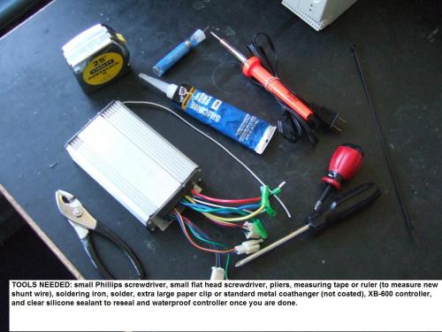
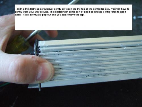
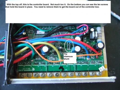
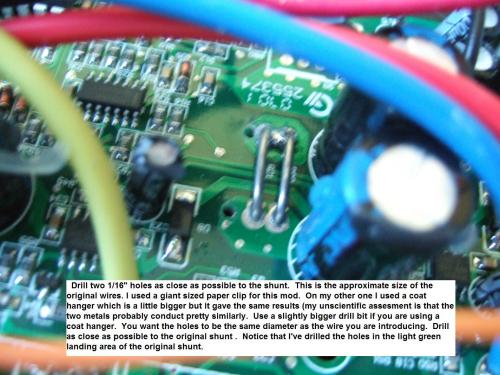
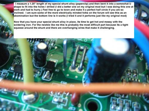
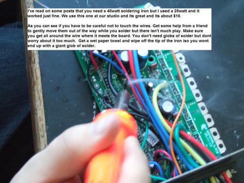
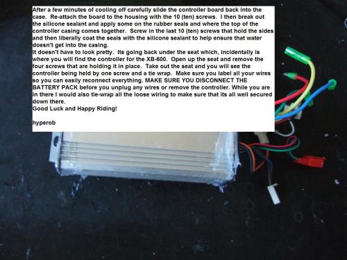
I finally got around to documenting the process for those still unsure of the process. Hopefully this will help a few people out who still aren't sure of the procedure.
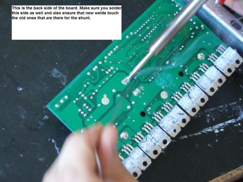
I'm wondering though...since you solder the new "shunt" on the underside of the board...why is it necessary to solder on the top side as well? If it's making good contact with the other two shunts on the underside wouldn't eliminating the soldering on the top of the board be a good thing...since it's not as easy getting to the base of the new shunt on the top with all those wires sort of in the way? Or could you put a 90 degree bend in each end of the new shunt, provided you can work it into the holes, such that the ends of the new shunt touch the welds of the existing shunts on the underside of the board...soldering each end directly into the existing solder bed of the existing shunts...and again forget about any soldering on the top of the board? What do you think?
I did the top and bottom to make sure that the shunt stays in place. There will be some vibration on the controller and I wouldn't want it shaking loose on the ride. Better safe than sorry and I don't want to have to open it again. Plus its soldered on both sides in the original as well.
Now that you have this...what's it going to be Gushar? Are you finally going to take the plunge? Get crazy with the Cheez-Wiz as they say and get some zip in that scoot?
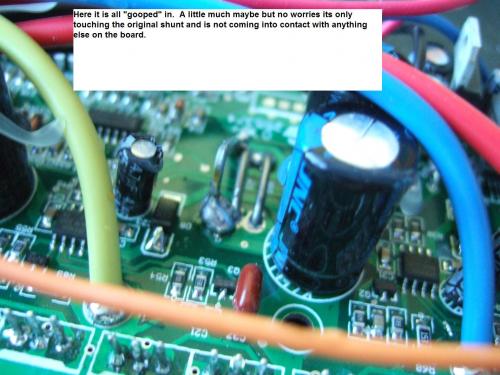
the 90' thing wont work because there is only a little room under the board and you wouldn't want to have the shunt make contact with the casing. :( I don't think that would be a good idea.
Oh...so there's not much space between the bottom of the board and the case. I just recall my electronics friend who taught me how to solder always had me soldering things on the underside of the board. And the goop of solder that you see on the topside sometimes was the flow of solder running through the hole to the top from the underside. Anyway, hey I'm the novice asking the questions...not the expert here! Wish my expert friend still lived in my town cause I'd just have him take a look and I can tell you he'd have that shunt in there looking like it came that way from the factory! He lives a state away now...but I'm telling you the guy is an electrical/electronics genius!
Well, you know I'd like that zip...but I also like the XB600 so much even like it is...and so I'm still debating. Of course this past weekend when lightning began popping all around me when I was out for a ride...I sure thought about more zip!!! YIKES!
I just want it to last as long as possible without a motor, controller, or other major component replacement...or lots of extra work/maintenance. That's one of the things I've enjoyed the most this past year since I got it...not having to do any work on it. It seems like "stuff" around the house is always breaking and I get tired of fixing stuff rather than using them! BTW, this month marks 1 year since I took delivery of my XB600. Can't recall exactly which day...but July of last year. Till I replaced the keyswitch recently...the only other thing I had to do was replace a tube.
I sure like hearing that Zerogas put 72v to the motor and controller, even for minutes, and didn't realize any adverse affects. That makes me think those components will last an awful long time...certainly with the stock power. And again, it's not really the cost of parts...but the time to work on things. So I don't know. I'm sure itching to do this mod...so we'll see....:-)
I really don't think that we are going to have a long term problem with the motor or controllers. We arent really going any "faster" just draining the batteries a little faster. Its still the same voltage going through the machine. I think the motor has a lot more grit than what we are seeing.
I have three small children, my twin girls are 4 and my boy is two and the last thing I want to add is more overhead to my life but this was totally doable in say three hours of time. I liked doing it cause it really got me acquainted with the bike in a more tactile way. Now I know how the wiring is put together. I got to see how the frame is welded and just how it was put together. That for me gives me a better feeling when I'm riding the bike. I am not a mechanic or an electrician in any way shape or form so its not like I do this all the time but I know in a pinch now I could probably replace most things on the bike or be able to figure out what might be going wrong and where.
Congratulations on the yearaversary!
Zerogas seems to me like he has way more knowledge of this stuff then I do and he's done some research. So far nothing adverse has happened to his bike and he rides a lot more than I do. Its great that he is out there at the forefront to see what's possible with these bikes. Its fun. I don't think I would ever do all the stuff he is doing (Way too Chuck Yaeger for me) but some of the stuff is most defenitely an improvement on what is there.
Actually, the solder on the top side of the board is not a good thing for the shunt. A shunt is supposed to have a measured resistance, and putting solder on the top of the board reduces that resistance substantially. It is better to just solder on the bottom side of the board and if some solder wicks up to the top of the board, that is ok.
Yeh...I hear what you're saying. I'm a records and information manager by profession...but I as well (although not for a living) have built houses and done about every mechanic's job on a vehicle. So I'm pretty handy. My electrical and electronics knowledge and abilities are more than the average person I think...but far from that of "real" electricians and electronic technicians. So, I'm always learning something new here when it comes to these things. I just appreciate the sharing of knowledge here. I'm like you. The more I see explained, etc. the more I know about my ride, and that makes me confident that I can repair it when something fails.
Like I wrote in another thread...I may just have to buy the upcoming 700li...and I may want to keep everything "stock" on the 600 so I can resell it easily. But then I may not buy the 700li in which case I will be itching to do this mod! That's why I wanted to make sure I understood exactly what you guys were doing.
I really like the fact too that Zerogas is doing the experimenting! I just think if I got that heavy into it I'd have to spend that time converting one of my cars to electric! But I can certainly appreciate his desire to see just what he can get out of this ride! And he certainly seems to be enjoying the experience...which is what alot of this is all about!
Ummm, I'd say all you guys have more knowledge about this stuff than me!! LOL What knowledge do I have?? I just try stuff out. :D If it works.. GREAT! If it doesn't, I change it back. LOL. My prior electric vehicle "mods" include raising the voltage on my daughter's power wheels from 6v to 18v... and that's it! I just figured, "Hey, if it worked on that piece of crapola it should be killer on this xb 600!" It is!!!!!!!! I love electric vehicles... they are so easy to mod. For the record, Gus, I'm already planning a vehicle conversion, as soon as I find a decent car with a manual tranny. I already got the "green light" <---- (pun intended) from my wife. I've even picked out a kit from cloud-ev.com that should propel me to 70+mph electric bliss! But that's another thread and another time... Stay Tuned
-Warren
Yesterday you were at 50mph now your looking towards 70mph. Just 700 more mph and SONIC BOOM BABY! The first EV past the sound barrier.....Good luck hanging on to your celll phone camera for that one!
Rob
P.S. You may be trying stuff out but you got the balls to go first. That's what I'm talking about.....Lead the way.
My work here was too illustrate the process that a few people had used so far to successfully mod their controllers. I am sure there is room for improvement on the process. The only issue I potentially see with yours is that you need at least 1.25" length of wire between the points (it seems everyone was kind of stressing that) but the distance between the contact points is less than 1" as far as I could measure. You would need a cuve in it wouldn't you? It would defenitely touch the casing at that point. Just a thought. Maybe there is a way around that.
You are missing the point of the shunt. The shunt serves as a fixed, standard resistance. The voltage drop across the shunt is proportional to current. We are lowering this fixed resistance value to lower the perceived current so that the controller sends more current to the motor than it was originally designed to do.
If you "simply solder a cable" you will short out the shunt. Globs of solder on the top of the board partially short out the shunt.
Just using "coat hangar wire" is enough of a compromize, because we are assuming that coat hangar wire has enough resistance in it so that a 1.5" length of it will not short out the shunt. Now if you start soldering wires to the back of the board, you are not even coming close to reducing the resistance of the shunt in a controlled way.
It doesn't matter whether you solder the loop of coat hangar wire to the top of the board or the bottom of the board, you need to make sure the coat hangar wire does not short out the shunt or anything else on the board. And you should solder it somewhat neatly so that you get as much of the 1.5 inches of coat hangar not compromized by solder as possible.
I decided to perform this mod today and now my bike is dead. I did everything as noted in the instructions but as I connected the power I heard a pop. I could not tell where the sound came from but I checked the fuses and they were all good. The green 30amp and the small glass (near the controller) fuses are ok. I don't know if there are any other fuses. The only thing not working is the hub motor. I get horn, lights, hi beams, turn signals working.
Where can I get a new controller and how much?
Really sorry to hear about your trouble doing the mod. I've done two this way and haven't had any worries.
Did you label the wires from the bike to the controller? Did you make sure that they were properly connected?
I've had stuff pop if its not properly fitted together. I believe the offending one for me was the white wire.
I would also do the checklist that arcticfox mentioned.
One question: Are you sure the solder points on the underside of the board are not touching the casing?
Also: You did disconnect the battery before you took out the controller and reattached the controller?
Please take a look at the wiring diagram of the scooter and check to make sure no wires got crossedxb-600wiring256.jpg (29.53 KB) Theres a bigger version on the site under the xb-600 modifications thread if you can't read this one.
If you do need another controller you can get it from xtreme or articfox probably. From X-Treme they run $65 delivered. Maybe AF can do better I don't know.
If you post some images of the mod maybe we can help figure out what happened.
If the pop came from inside the controller, you will be able to see it by looking at the controller board. If the controller board still looks fine, your controller is still fine, and some wire got shorted and probably a connector is fried.
Some other thread suggest to short thick red and black wires on the controller to avoid any unwanted electrical charges by way of the solderer .Soldering batteries with butane is safer as it has damaged my batteries operated pinpoint solderer.
You are missing the point of the shunt. The shunt serves as a fixed, standard resistance. The voltage drop across the shunt is proportional to current. We are lowering this fixed resistance value to lower the perceived current so that the controller sends more current to the motor than it was originally designed to do.
If you "simply solder a cable" you will short out the shunt. Globs of solder on the top of the board partially short out the shunt.
Just using "coat hangar wire" is enough of a compromize, because we are assuming that coat hangar wire has enough resistance in it so that a 1.5" length of it will not short out the shunt. Now if you start soldering wires to the back of the board, you are not even coming close to reducing the resistance of the shunt in a controlled way.
It doesn't matter whether you solder the loop of coat hangar wire to the top of the board or the bottom of the board, you need to make sure the coat hangar wire does not short out the shunt or anything else on the board. And you should solder it somewhat neatly so that you get as much of the 1.5 inches of coat hangar not compromized by solder as possible.
Thank you for the explanation, but I am still not clear about it...
Do you mean there is so much current going through the wires that it raises their temperature and so increases the resistance?
Or is the resistance fixed and the wires are not supposed to heat up?
Why not use a high wattage resistor instead of coat hanger wire? (I do not believe the USA have standardized coat hangers...yet!)
Could you not just put some solder onto the ends (on the upper side of the PCB) of one or both of the existing wires to reduce their resistance?
I believe I also remember someone (Andrew or LinkofHyrule ?) posting that you could just add one or a few strands of wire to a shunt...but that might have been for a different vehicle altogether.
Or cut out part or all of one of the existing wires and replace it with a resistor, instead of drilling holes and adding solder blobs on the underside which can apparently make contact with the case?
Hope this does not sound like I want to nag or something....but it seems to be an important issue. (And as the last few posts show, not without risks...sorry to hear about your misfortune, audiophil2)
In case it has all been discussed and explained in detail before, then please give me the link to it and I'll read up!
Mr. Mik
This information may be used entirely at your own risk.
Phil,
That's horrible bro, are you sure you put the coathanger in the right place? I've run this mod for several months now with absolutely no problems. Even at 72v my controller held up. Seems to me you may have a loose connection. These little white connectors are crap. I had to push some of the terminals back into the connectors on mine, because they were "falling" out. :( Hope you get it straight.
- Warren
I can't comment on some of your questions because they are beyond my electrical understanding but I can tell you that the "coat hanger" thing came from a post about a completely different controller for a different (and bigger bike). I've done two conversions with a coat hanger and with a giant sized paperclip that matched perfectly the diameter of the original shunt. Both gave me the same result.
I think the lenght was also mentioned in the same thread but on the xb-600 the shunt measures less than 1". Its a different length than the shunt on the original post I believe so I don't know if the 1.5" is necessarily the magic number for resistance.
I don't know if some on this thread have actually done any of the modding mentioned but yeah there are some principles to be observed but you also have to put the process in context of the materials you are working with.
Thank you for the explanation, but I am still not clear about it...
Not your fault. I am not good at explaining it.
Do you mean there is so much current going through the wires that it raises their temperature and so increases the resistance?
Or is the resistance fixed and the wires are not supposed to heat up?
The shunt wires should never have so much resistance/voltage drop that they heat up. They only provide a small voltage drop that can be measured to indicate how much current is used by the motor. The electronics uses this measure of current to keep the components in the controller and external wiring from being damaged. The controller limits the maximum current that can be used by the motor.
Why not use a high wattage resistor instead of coat hanger wire? (I do not believe the USA have standardized coat hangers...yet!)
There should not be many watts of power consumed by the shunt - the resistance is very low. So we aren't really looking for a high wattage resistor - we are looking for a highly accurate low-resistance resistor. A fixed length of shunt wire is a better controlled resistance for that low of a resistance than any resistor could be - that is why they make shunt wire. The accuracy of the resistance of the shunt wire determines the accuracy of the current measurement used by the controller. There is no question that a better solution would be to use shunt wire instead of a coat hangar. Maybe not all coat hangars are made the same, and they definitely are not manufactured to the precision of shunt wire.
Could you not just put some solder onto the ends (on the upper side of the PCB) of one or both of the existing wires to reduce their resistance?
You could, but it sure seems that would be even less accurate than using 1.5" of some unknown coat hangar wire.
I believe I also remember someone (Andrew or LinkofHyrule ?) posting that you could just add one or a few strands of wire to a shunt...but that might have been for a different vehicle altogether.
Maybe. But while the voltage drop across the shunt is low, the current passing through the shunt is 20 amps or more. It seems to me that thin strands of highly conductive wire would burn up, while a length of not-too-good-conducting coat hangar wire would carry the current easily.
Or cut out part or all of one of the existing wires and replace it with a resistor, instead of drilling holes and adding solder blobs on the underside which can apparently make contact with the case?
Hope this does not sound like I want to nag or something....but it seems to be an important issue. (And as the last few posts show, not without risks...sorry to hear about your misfortune, audiophil2)
Not nagging at all - it is helpful to understand what the shunt does, at least enough to stress to people that they should try to follow the directions exactly. Seemingly subtle changes, like putting too much solder on top of the shunt or using copper-coated coathangars, could have disastrous results.
Here is probably more than you will ever want to know about making shunts:
I understand it now. I almost put a shunt into the Vectux to measure the amps going in and out of the battery, but then used an existing hall effect sensor around the cable instead.
Basically, all the current used by the motor goes through the two shunt wires. They have a very low resistance, but enough to cause a small voltage drop across them.
Ohms law lets you (or in this case the motor controller) calculate the current going through the shunt wires if you know the resistance and the voltage drop.
V/I=R --> I = V/R
The controller is fooled into "believing" there is less current going through because no-one told it there is now a coat-hanger reducing the resistance....
Mr. Mik
This information may be used entirely at your own risk.
My controller is fried. I won't bother posting pics cause it does not show anything. I ordered a new controller today so hopefully I will be riding again by next week.
I plan on upgrading to a 3500Li in a few months but I am willing to try this mod one more time before the upgrade.
Phil
Really really sorry to hear about the controller frying. Any idea what went wrong? You said the controller doesn't show anything. You mean you can't see any difference on the controller from pre mod to post mod?
Bummer. :(
On Friday night after work I decided to take a long ride up some hilly areas in my community to really test out the scooter and the mods. About 4 miles into the ride and after 4 or 5 pretty steep hills at full throttle the bike gave out on me. Once I got it home I opened it up and found that the blade fuse and the holder had melted and I had lost power. Upon further investigation, it looked like the fuse might have been improperly set into the box with the blade sandwiched between one connector and the plastic casing. I hadn't opened it since getting the bike from the manufacturer so it probably came that way. You should check to make sure that this doesn't happen to you. I am sure I was drawing more amps then I should with the mod but I think the improper placement of the fuse had something to do with it.
I couldn't find the exact replacement part from X-Treme so I found a temporary fuse box and some new fuses (the fuses that come from the manu are really really cheap compared to the ones I got at Radio Shack.) I replaced the box and everything was working fine again. On Sunday night I decided to redo the same trip to see how it would go and the bike did it all without a hiccup (The whole 8 miles up and down hills). I will say that I stayed one notch back on the accelerator just in case but it only reduced my speed to about 16mph going up some pretty steep hills. I checke the condition of the fuse after the ride and it appeared unchanged.
I have to say after a few weeks of ownership that some of the parts are pretty low grade. The screws and bolts especially. The bolts that hold the seat have already stripped after only a few times of taking the seat off. I went to my local hardware store and when I showed them the screw I needed to replace they were amazed at the low quality of the original. I replaced all the screws and bolts I could easily see on the bike for about 8 bucks. It was well worth the time and money for me to not have to worry about stripping screws all the time.
Congrats, Rob!!
Glad to hear all is well with your 60v mod! Get some vids on youtube so we can all see you zooming around!! I got my 4110 mosfets in today, so 72v is not far off. Helloooo 35mph for good this time!


Nice post, Rob.
You got almost as much solder on there as I did! LOL. Good pics.
Keep the rubber side down and the shiny side up.
Wow...thanks for taking the time to provide this!
I'm wondering though...since you solder the new "shunt" on the underside of the board...why is it necessary to solder on the top side as well? If it's making good contact with the other two shunts on the underside wouldn't eliminating the soldering on the top of the board be a good thing...since it's not as easy getting to the base of the new shunt on the top with all those wires sort of in the way? Or could you put a 90 degree bend in each end of the new shunt, provided you can work it into the holes, such that the ends of the new shunt touch the welds of the existing shunts on the underside of the board...soldering each end directly into the existing solder bed of the existing shunts...and again forget about any soldering on the top of the board? What do you think?
Gushar
Gus
Hey Gushar,
I did the top and bottom to make sure that the shunt stays in place. There will be some vibration on the controller and I wouldn't want it shaking loose on the ride. Better safe than sorry and I don't want to have to open it again. Plus its soldered on both sides in the original as well.
Now that you have this...what's it going to be Gushar? Are you finally going to take the plunge? Get crazy with the Cheez-Wiz as they say and get some zip in that scoot?
Hey Gus,
the 90' thing wont work because there is only a little room under the board and you wouldn't want to have the shunt make contact with the casing. :( I don't think that would be a good idea.
Oh...so there's not much space between the bottom of the board and the case. I just recall my electronics friend who taught me how to solder always had me soldering things on the underside of the board. And the goop of solder that you see on the topside sometimes was the flow of solder running through the hole to the top from the underside. Anyway, hey I'm the novice asking the questions...not the expert here! Wish my expert friend still lived in my town cause I'd just have him take a look and I can tell you he'd have that shunt in there looking like it came that way from the factory! He lives a state away now...but I'm telling you the guy is an electrical/electronics genius!
Well, you know I'd like that zip...but I also like the XB600 so much even like it is...and so I'm still debating. Of course this past weekend when lightning began popping all around me when I was out for a ride...I sure thought about more zip!!! YIKES!
I just want it to last as long as possible without a motor, controller, or other major component replacement...or lots of extra work/maintenance. That's one of the things I've enjoyed the most this past year since I got it...not having to do any work on it. It seems like "stuff" around the house is always breaking and I get tired of fixing stuff rather than using them! BTW, this month marks 1 year since I took delivery of my XB600. Can't recall exactly which day...but July of last year. Till I replaced the keyswitch recently...the only other thing I had to do was replace a tube.
I sure like hearing that Zerogas put 72v to the motor and controller, even for minutes, and didn't realize any adverse affects. That makes me think those components will last an awful long time...certainly with the stock power. And again, it's not really the cost of parts...but the time to work on things. So I don't know. I'm sure itching to do this mod...so we'll see....:-)
Gushar
Gus
Hey Gus,
I really don't think that we are going to have a long term problem with the motor or controllers. We arent really going any "faster" just draining the batteries a little faster. Its still the same voltage going through the machine. I think the motor has a lot more grit than what we are seeing.
I have three small children, my twin girls are 4 and my boy is two and the last thing I want to add is more overhead to my life but this was totally doable in say three hours of time. I liked doing it cause it really got me acquainted with the bike in a more tactile way. Now I know how the wiring is put together. I got to see how the frame is welded and just how it was put together. That for me gives me a better feeling when I'm riding the bike. I am not a mechanic or an electrician in any way shape or form so its not like I do this all the time but I know in a pinch now I could probably replace most things on the bike or be able to figure out what might be going wrong and where.
Congratulations on the yearaversary!
Zerogas seems to me like he has way more knowledge of this stuff then I do and he's done some research. So far nothing adverse has happened to his bike and he rides a lot more than I do. Its great that he is out there at the forefront to see what's possible with these bikes. Its fun. I don't think I would ever do all the stuff he is doing (Way too Chuck Yaeger for me) but some of the stuff is most defenitely an improvement on what is there.
Actually, the solder on the top side of the board is not a good thing for the shunt. A shunt is supposed to have a measured resistance, and putting solder on the top of the board reduces that resistance substantially. It is better to just solder on the bottom side of the board and if some solder wicks up to the top of the board, that is ok.
Yeh...I hear what you're saying. I'm a records and information manager by profession...but I as well (although not for a living) have built houses and done about every mechanic's job on a vehicle. So I'm pretty handy. My electrical and electronics knowledge and abilities are more than the average person I think...but far from that of "real" electricians and electronic technicians. So, I'm always learning something new here when it comes to these things. I just appreciate the sharing of knowledge here. I'm like you. The more I see explained, etc. the more I know about my ride, and that makes me confident that I can repair it when something fails.
Like I wrote in another thread...I may just have to buy the upcoming 700li...and I may want to keep everything "stock" on the 600 so I can resell it easily. But then I may not buy the 700li in which case I will be itching to do this mod! That's why I wanted to make sure I understood exactly what you guys were doing.
I really like the fact too that Zerogas is doing the experimenting! I just think if I got that heavy into it I'd have to spend that time converting one of my cars to electric! But I can certainly appreciate his desire to see just what he can get out of this ride! And he certainly seems to be enjoying the experience...which is what alot of this is all about!
Gushar
Gus
Ummm, I'd say all you guys have more knowledge about this stuff than me!! LOL What knowledge do I have?? I just try stuff out. :D If it works.. GREAT! If it doesn't, I change it back. LOL. My prior electric vehicle "mods" include raising the voltage on my daughter's power wheels from 6v to 18v... and that's it! I just figured, "Hey, if it worked on that piece of crapola it should be killer on this xb 600!" It is!!!!!!!! I love electric vehicles... they are so easy to mod. For the record, Gus, I'm already planning a vehicle conversion, as soon as I find a decent car with a manual tranny. I already got the "green light" <---- (pun intended) from my wife. I've even picked out a kit from cloud-ev.com that should propel me to 70+mph electric bliss! But that's another thread and another time... Stay Tuned
-Warren
Keep the rubber side down and the shiny side up.
Hey Warren,
Yesterday you were at 50mph now your looking towards 70mph. Just 700 more mph and SONIC BOOM BABY! The first EV past the sound barrier.....Good luck hanging on to your celll phone camera for that one!
Rob
P.S. You may be trying stuff out but you got the balls to go first. That's what I'm talking about.....Lead the way.
Hi,
I'm also trying stuff out cautiously...The way to go!
Maybe I am missing something, but could you not simply solder a cable between the soldering points on the underside of the PCB?
No drilling etc?
I believe the electrons don't mind which way they go around to the other side...
And a cable would be no thicker than the solder blobs, but insulated against contact with the case.
I'd also add some hot glue if the clearance to any conducting cover is too small.
Mr. Mik
This information may be used entirely at your own risk.
There is always a way if there is no other way!
Hi Mr.MIk,
My work here was too illustrate the process that a few people had used so far to successfully mod their controllers. I am sure there is room for improvement on the process. The only issue I potentially see with yours is that you need at least 1.25" length of wire between the points (it seems everyone was kind of stressing that) but the distance between the contact points is less than 1" as far as I could measure. You would need a cuve in it wouldn't you? It would defenitely touch the casing at that point. Just a thought. Maybe there is a way around that.
hyperob
Mr. Mik,
You are missing the point of the shunt. The shunt serves as a fixed, standard resistance. The voltage drop across the shunt is proportional to current. We are lowering this fixed resistance value to lower the perceived current so that the controller sends more current to the motor than it was originally designed to do.
If you "simply solder a cable" you will short out the shunt. Globs of solder on the top of the board partially short out the shunt.
Just using "coat hangar wire" is enough of a compromize, because we are assuming that coat hangar wire has enough resistance in it so that a 1.5" length of it will not short out the shunt. Now if you start soldering wires to the back of the board, you are not even coming close to reducing the resistance of the shunt in a controlled way.
It doesn't matter whether you solder the loop of coat hangar wire to the top of the board or the bottom of the board, you need to make sure the coat hangar wire does not short out the shunt or anything else on the board. And you should solder it somewhat neatly so that you get as much of the 1.5 inches of coat hangar not compromized by solder as possible.
I decided to perform this mod today and now my bike is dead. I did everything as noted in the instructions but as I connected the power I heard a pop. I could not tell where the sound came from but I checked the fuses and they were all good. The green 30amp and the small glass (near the controller) fuses are ok. I don't know if there are any other fuses. The only thing not working is the hub motor. I get horn, lights, hi beams, turn signals working.
Where can I get a new controller and how much?
Check for smells.
Check your solder joints. Check any capacitors on the board. Inspect the circuit board for any blown traces.
If you can take high-res pictures of the board, please post them.
<table border="0" style="border:1px solid #999999; padding:10px;"><tr><td>
<a href="http://www.BaseStationZero.com">[img]http://visforvoltage.org/files/u419...
[size=1][color=black]www.[/color][color=#337799]BaseStationZero[/color][co
Hey audiophil2,
Really sorry to hear about your trouble doing the mod. I've done two this way and haven't had any worries.
Did you label the wires from the bike to the controller? Did you make sure that they were properly connected?
I've had stuff pop if its not properly fitted together. I believe the offending one for me was the white wire.
I would also do the checklist that arcticfox mentioned.
One question: Are you sure the solder points on the underside of the board are not touching the casing?
Also: You did disconnect the battery before you took out the controller and reattached the controller?
Please take a look at the wiring diagram of the scooter and check to make sure no wires got crossedxb-600wiring256.jpg (29.53 KB) Theres a bigger version on the site under the xb-600 modifications thread if you can't read this one.
If you do need another controller you can get it from xtreme or articfox probably. From X-Treme they run $65 delivered. Maybe AF can do better I don't know.
If you post some images of the mod maybe we can help figure out what happened.
If the pop came from inside the controller, you will be able to see it by looking at the controller board. If the controller board still looks fine, your controller is still fine, and some wire got shorted and probably a connector is fried.
What kind of coat hangar did you use?
Some other thread suggest to short thick red and black wires on the controller to avoid any unwanted electrical charges by way of the solderer .Soldering batteries with butane is safer as it has damaged my batteries operated pinpoint solderer.
Thank you for the explanation, but I am still not clear about it...
Do you mean there is so much current going through the wires that it raises their temperature and so increases the resistance?
Or is the resistance fixed and the wires are not supposed to heat up?
Why not use a high wattage resistor instead of coat hanger wire? (I do not believe the USA have standardized coat hangers...yet!)
Could you not just put some solder onto the ends (on the upper side of the PCB) of one or both of the existing wires to reduce their resistance?
I believe I also remember someone (Andrew or LinkofHyrule ?) posting that you could just add one or a few strands of wire to a shunt...but that might have been for a different vehicle altogether.
Or cut out part or all of one of the existing wires and replace it with a resistor, instead of drilling holes and adding solder blobs on the underside which can apparently make contact with the case?
Hope this does not sound like I want to nag or something....but it seems to be an important issue. (And as the last few posts show, not without risks...sorry to hear about your misfortune, audiophil2)
In case it has all been discussed and explained in detail before, then please give me the link to it and I'll read up!
Mr. Mik
This information may be used entirely at your own risk.
There is always a way if there is no other way!
I'll post pics when I get home from work today in about 9 hours. Thanks for the help everyone.
Phil,
That's horrible bro, are you sure you put the coathanger in the right place? I've run this mod for several months now with absolutely no problems. Even at 72v my controller held up. Seems to me you may have a loose connection. These little white connectors are crap. I had to push some of the terminals back into the connectors on mine, because they were "falling" out. :( Hope you get it straight.
- Warren
Keep the rubber side down and the shiny side up.
Hi Mr.Mik
I can't comment on some of your questions because they are beyond my electrical understanding but I can tell you that the "coat hanger" thing came from a post about a completely different controller for a different (and bigger bike). I've done two conversions with a coat hanger and with a giant sized paperclip that matched perfectly the diameter of the original shunt. Both gave me the same result.
I think the lenght was also mentioned in the same thread but on the xb-600 the shunt measures less than 1". Its a different length than the shunt on the original post I believe so I don't know if the 1.5" is necessarily the magic number for resistance.
I don't know if some on this thread have actually done any of the modding mentioned but yeah there are some principles to be observed but you also have to put the process in context of the materials you are working with.
Happy Riding
hyperob
Not your fault. I am not good at explaining it.
The shunt wires should never have so much resistance/voltage drop that they heat up. They only provide a small voltage drop that can be measured to indicate how much current is used by the motor. The electronics uses this measure of current to keep the components in the controller and external wiring from being damaged. The controller limits the maximum current that can be used by the motor.
There should not be many watts of power consumed by the shunt - the resistance is very low. So we aren't really looking for a high wattage resistor - we are looking for a highly accurate low-resistance resistor. A fixed length of shunt wire is a better controlled resistance for that low of a resistance than any resistor could be - that is why they make shunt wire. The accuracy of the resistance of the shunt wire determines the accuracy of the current measurement used by the controller. There is no question that a better solution would be to use shunt wire instead of a coat hangar. Maybe not all coat hangars are made the same, and they definitely are not manufactured to the precision of shunt wire.
You could, but it sure seems that would be even less accurate than using 1.5" of some unknown coat hangar wire.
Maybe. But while the voltage drop across the shunt is low, the current passing through the shunt is 20 amps or more. It seems to me that thin strands of highly conductive wire would burn up, while a length of not-too-good-conducting coat hangar wire would carry the current easily.
Not nagging at all - it is helpful to understand what the shunt does, at least enough to stress to people that they should try to follow the directions exactly. Seemingly subtle changes, like putting too much solder on top of the shunt or using copper-coated coathangars, could have disastrous results.
Here is probably more than you will ever want to know about making shunts:
http://tinyurl.com/366awg
Thanks for that!
I understand it now. I almost put a shunt into the Vectux to measure the amps going in and out of the battery, but then used an existing hall effect sensor around the cable instead.
Basically, all the current used by the motor goes through the two shunt wires. They have a very low resistance, but enough to cause a small voltage drop across them.
Ohms law lets you (or in this case the motor controller) calculate the current going through the shunt wires if you know the resistance and the voltage drop.
V/I=R --> I = V/R
The controller is fooled into "believing" there is less current going through because no-one told it there is now a coat-hanger reducing the resistance....
Mr. Mik
This information may be used entirely at your own risk.
There is always a way if there is no other way!
My controller is fried. I won't bother posting pics cause it does not show anything. I ordered a new controller today so hopefully I will be riding again by next week.
I plan on upgrading to a 3500Li in a few months but I am willing to try this mod one more time before the upgrade.
Phil
Any idea what caused it to fry? Did your solder spill over to other areas on the board?
Keep the rubber side down and the shiny side up.
Hey Phil,
Really really sorry to hear about the controller frying. Any idea what went wrong? You said the controller doesn't show anything. You mean you can't see any difference on the controller from pre mod to post mod?
Bummer. :(
rob
Hey Guys,
On Friday night after work I decided to take a long ride up some hilly areas in my community to really test out the scooter and the mods. About 4 miles into the ride and after 4 or 5 pretty steep hills at full throttle the bike gave out on me. Once I got it home I opened it up and found that the blade fuse and the holder had melted and I had lost power. Upon further investigation, it looked like the fuse might have been improperly set into the box with the blade sandwiched between one connector and the plastic casing. I hadn't opened it since getting the bike from the manufacturer so it probably came that way. You should check to make sure that this doesn't happen to you. I am sure I was drawing more amps then I should with the mod but I think the improper placement of the fuse had something to do with it.
I couldn't find the exact replacement part from X-Treme so I found a temporary fuse box and some new fuses (the fuses that come from the manu are really really cheap compared to the ones I got at Radio Shack.) I replaced the box and everything was working fine again. On Sunday night I decided to redo the same trip to see how it would go and the bike did it all without a hiccup (The whole 8 miles up and down hills). I will say that I stayed one notch back on the accelerator just in case but it only reduced my speed to about 16mph going up some pretty steep hills. I checke the condition of the fuse after the ride and it appeared unchanged.
I have to say after a few weeks of ownership that some of the parts are pretty low grade. The screws and bolts especially. The bolts that hold the seat have already stripped after only a few times of taking the seat off. I went to my local hardware store and when I showed them the screw I needed to replace they were amazed at the low quality of the original. I replaced all the screws and bolts I could easily see on the bike for about 8 bucks. It was well worth the time and money for me to not have to worry about stripping screws all the time.
Cheers
Congrats, Rob!!
Glad to hear all is well with your 60v mod! Get some vids on youtube so we can all see you zooming around!! I got my 4110 mosfets in today, so 72v is not far off. Helloooo 35mph for good this time!
Keep the rubber side down and the shiny side up.
Pages