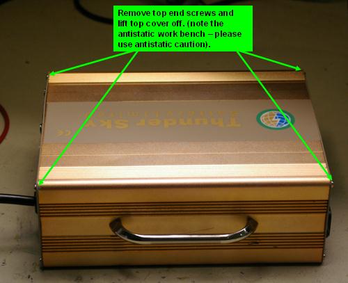
Greetings - I have been asked how I changed the TSL60-10 charger to handle charging 21 LFP cells on my XM-3500LI from the original 20 cells.
First, let me mention you undertake this at your own risk, you will void your warranty, and this info is free so I do not assume any responsibility for how it is used or any damages that occur from it! ;)
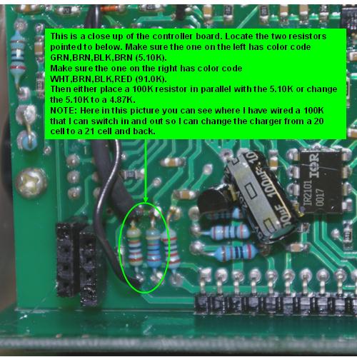
Now, below is what is needed for changing this charger to scale its output by 5% high to cover 21 cells in series from the original 20. I hope it makes sense (note - if you want to go more than 21, I would hesitate as the electronic components and design might run out of margin and you will get a failure - I feel comfortable with just a 5% increase).


I hereby loan eped my disclaimer. ;)
The author of this post isn't responsible for any injury, disability or dismemberment, death, financial loss, illness, addiction, hereditary disease, or any other undesirable consequence or general misfortune resulting from use of the "information" contai
typically you'll want to look for 1% accurate resistors.
XM-3000...
-DC-DC converter replaced with a Dell D220P-01 power supply.
-72V mod
-Expensive bank charger until I come up with something better... Still trying.
-
Thanks eped, great info.
Does this mean you got a schematic somewhere, or didja just use your incredible psychic powers to mind meld it?
R
Sorry, no schematic. Since I am a EE working for a company that sells power control ICs, I have a pretty good idea on how these work and just traced down the output voltage sense and how it is fed back.
Green electric power and use thereof; what more do we need?
Hi eped,
Hey I was just wondering about your 21st cell.
How did you go about "compressing" your added cell?
Did you put some aluminium plates and steel straps around it, like the stock method? duct tape?
Is this as important as I've read?
I've read that if not compressed(restrained), the repeated swelling and shrinkage of Lithium cells can result in separation of the electrolyte paste from the conductors, reducing function and leaving room for gas buildup with possible hazard.
What's your take on this?
Ross
Hi Ross - I should receive my 21st cell tomorrow (they have been back ordered at Elite) and then plan to strap it in somehow. I was planning just basic metal straps to secure it and give some support around the case but nothing major.
This image is out of the Thunder Sky manual and if you do not over/under charge the cell you should not experience swelling. With the BMS, Paktrakr, and modified "fuel" gauge I hope to avoid that! ;)
Green electric power and use thereof; what more do we need?
From the ThunderSky picture, it looks like all the swelling is on the ends of the pack, not in the middle. Their "restoration" squeeze plates apparently just re-form the ends. Is that correct?
In all the installations I have seen, the ends (where one connects the thick conductors) are not constrained at all. They are usually packed in very closely, side to side, but that would seem to be just because they are tryinig to use the smallest battery case possible.
With the ridges on the sides, it looks like one could have (even force) some "cooling" air-flow around the batteries. Is there any such air-flow around the batteries in the XM-3500li?
Thanks, Gary
Cheers, Gary
XM-5000Li, wired for cell voltage measuring and logging.
eped - excellent info!
I just did this mod on my TSL60-15 that was factory adjusted for 21 cells and lists 75V on the dataplate. The controller board looks identical to your TSL60-10 including the resistor values.
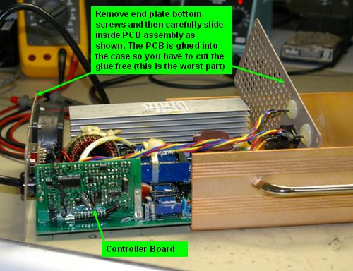
After about 6 months of charges the glue had broken away from the aluminum charger case so sliding the main board out fo the case was effortless.
Thank You!
Hi, I have the same charger, but for 19s/69V. The resistors have the same value as yours. It means, that manufacturer sets the voltage elsewhere. Or maybe is the voltage hardcoded into firmware? How far one can increase the voltage of this charger and stay safe? Is 24s (86.4V) possible?
I can GUARANTEE that if you don't STRONGLY strap that single cell, it will puff up in the middle under normal operating conditions. I know because I just used zip ties to hold it in place. Went for a ride pulling the normal 100Amps and after the 25 minute ride the cell was all puffed up and within a week was reading 0 volts after a ride. If you dont strap it, it will puff up and destoy itself.
------------------------------
eRider 8000w Scooter - PDT Version
72v 50AH CHL battery
350A Sevcon controller
24km: Delivered - 24 September 2011
2490km: Installed dual 35w HID lights Bi-Xenon Projectors - 27 November 2011
8313km: Installed BMS -
pcarlson,
I have a fair amount of experience with Thundersky cells in their various incarnations - Thundersky, TS-Ningbo, and now the much improved Winston LYP cells. I have used 40AH cells discharged at up to 100 amps and the only case of swelling was when a cell was over-discharged down to near zero volts. You may have had a bad cell?
I have only seen bulging on defective or abused cells
I don't strap any cells ever, simply because you don't have to
What is curious is why your extra cell failed, presumably you top balanced it with the rest of the pack when you put it in?
Matt
Daily Ride:
2007 Vectrix, modified with 42 x Thundersky 60Ah in July 2010. Done 194'000km
Thanks for the great contribution I have been very useful as I get the scooter with a charger for 19 cells, with 20 the scooter.
Greetings from Spain.