I'm posting a picture of the XB-500 Controller and the wiring as what I know or believe to be true. Please help me identify the wires and connectors if you know where they go. ? Next to ones I am not sure about. Feel free to copy this and/or edit. Hopefully once it's correct and verified it will help someone else later.
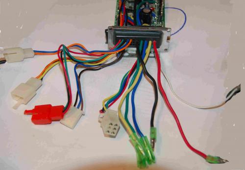
From Right to Left
[Right Side Group]
White Single = ?
Red Single = Positive input from battery
Black Single = Negative input from battery
Blue Single = To motor
Green Single = To motor
Yellow Single = To motor
White 6 Connector = Motor Hall Sensor (6 connector but only 5 wires)
[Left Side Group]
White 3 Connector = ? (Brown Blue Black)
Red 3 Connector = ? Throttle (Red Black Green)
White 3 Connector = ? E-Brakes (Orange Yellow Black)
White 2 Connector = ? Speedometer (Orange Blue)
-Whome

Somewhere on this board, there is a link to an entire XB-600 schematic, but I can't find it right now. Here is a section of that schematic that I clipped out and posted for another question. It shows the color of the wires, which look to be the same as your photo above. Ignore the red circle;
I hope this helps,
Tom
Thank you. That helped a good bit. So the only thing left to identify is the on White 3 prong connector with the (Orange Yellow Black) wires, and the lone white single wire.
From Right to Left
[Right Side Group]
White Single = ?
Red Single = Positive input from battery
Black Single = Negative input from battery
Blue Single = To motor
Green Single = To motor
Yellow Single = To motor
White 6 Connector = Motor Hall Sensor (6 connector but only 5 wires)
[Left Side Group]
White 3 Connector = E-Brakes(Brown Blue Black)
Red 3 Connector = Throttle (Red Black Green)
White 3 Connector = ? (Orange Yellow Black)
White 2 Connector = Ignition Switch (Orange Blue)
-----------------------------------------------------------------------------------------------------------------------
Just FYI and comparison:
This is the controller I ordered today to replace the stock controller on my Xb-500.
-Whome
Hi!
Here is the link to the xb-600 wiring diagram
http://www.markmilley.com/ev/xb600wiring.png
The single white wire is for the speedometer.
maybe the "Orange Yellow Black" connector did not go anywhere. On my xb-600 controller there are connectors that are not on the plan. I don't know what they are for.
Thanks so much for the wiring diagram Gendronw!
From Right to Left
[Right Side Group]
White Single = Speedometer
Red Single = Positive input from battery
Black Single = Negative input from battery
Blue Single = To motor
Green Single = To motor
Yellow Single = To motor
White 6 Connector = Motor Hall Sensor (6 connector but only 5 wires)
[Left Side Group]
White 3 Connector = E-Brakes(Brown Blue Black)
Red 3 Connector = Throttle (Red Black Green)
White 3 Connector = ? (Orange Yellow Black) --------?????-----------------> Brake Lights ?
White 2 Connector = Ignition Switch (Orange Blue)
-Whome
Some controllers have a purple wire (not white) for the speedometer.
I don't think the (Orange Yellow Black) plug is for brake lights. Normally all lights are fed by the 48v/12v converter.
On the plan you can see the two diodes in parallel connected to the brake light. It's probably the same for Xb-500.
Nice project you got there !
good luck !
Thanks everyone for your help. Here is the completed list. I will test and confirm when I get the new controller.
From Right to Left
[Right Side Group]
White Single = Speedometer
Red Single = Positive input from battery
Black Single = Negative input from battery
Blue Single = To motor
Green Single = To motor
Yellow Single = To motor
White 6 Connector = Motor Hall Sensor (6 connector but only 5 wires)
[Left Side Group]
White 3 Connector = E-Brakes(Brown Blue Black)
Red 3 Connector = Throttle (Red Black Green)
White 3 Connector = ? (Orange Yellow Black) Not used on the XB-500
White 2 Connector = Ignition Switch (Orange Blue)
-Whome
Well I just wanted to thank everyone for contributing on this. I succesfully installed a new Infineon controller in the scooter this weekend and took it out for a test run this morning. It runs great and is only running on the original stock batteries thus far. The only thing I was unable to get working so far is the speedometer.
I installed a 72 Volt – 45 Amp Infineon controller that can run any voltage between 27v and 90v. It also has a variable LVC. I plan to go to 60volts tommorow. . . .
Now ZZZZZZZZZZZ
-Whome
Where'd you buy it? How does it do on hills?
Well . . . I actually bought it from a guy on the Endless-sphere Forum who customizes controllers. This one was actually made for a regular bike with the new Wilderness Energy Bl-36 Hub motor, but the sensorless mod on it did not work quite like I expected, so I tried it on the XB-500.
It does great on hills. Only slows down a little bit, but I have blown fuses, so I am now using a 40 amp fuse.
I upgraded to 60v today and it only runs a little faster(not really impressed) but I had some wiring problems pop up. I may need to rewire some things before I try 72v.
-Whome
This is what happens to the tiny little Chinese wires when you mod your XB-X00 to 72v and run too many amps with the shunt mod. They get really hot and melt together. This was not the only spot. I went for a ride Monday evening and had to push my scooter home about 3/4 mile. The motor was draggin the whole way too since the wires melted to each other and closed the circuit. The motor was acting like a brake.
I highly recommend running new wires for the motor if you plan to use these mods on your scooter as a commuter.
-Whome
4 months ago, I also got to push The Beast 1/4 mile with a locked wheel. If I knew then...
Tip in case there's a next time: make sure you have a tool kit on board, especially a Phillips head screw driver. If you run into a problem like this again, disconnect the battery and then disconnect the controller and your wheel will unlock. Another secret, if you can do something with your battery box (have someone come pick it up or leave it at a neighbor's house), the scooter actually sorta rides much more like a bike minus the 40+ pounds of battery. Even if you don't pedal it, it's much easier to push that way.
I actually did have some tools with me, and I disconnected everything. Batteries, controller, wires to the controller. However in this case, because the wires were melted in several spots (especially where the plastic wire tires were used) inside the enclosed white vinyl wire wraps along the frame of the bike.
That caused the motor to act like a generator and also gave me a clue to what was wrong when I got it back home to work on it.
Good idea though about leaving the battery, but it was getting dark. I don't think I will ever put the pedals on this. I'd rather push it.
FYI: The bike seems to run a lot faster and accelerate better now with the new wires! This could be new mod in itself. Just replacing the tiny 16gauge wiring with 10gauge has made a noticeable difference in performance. Of course I am also not using the stock controller, so it would make sense that the small wires were not able to deliver what the new controller was able to supply, but I was not getting the speed I expected or had read of others getting with the mods before either.
This new controller is capable of 40-45amps. I only ran the new wiring from the controller in the front to the point in the rear where the motor wires plugged into the wiring harness. So . . . . there is still a potential for melting between that point and the motor, but at least it is in the open and can get more air to cool off. I did notice also that the wiring from the motor to the rear harness connection is much stiffer than the original wiring that ran from the controller in front.
Anyone know the actual "true" specs on the amps output of the stock controller on the xb-500 and xb-600? According to the X-Treme Scooters website it boasts a 48 Amp Circuit for the xb-500,600. However the xb-508 lists a 56 Amp Circuit. I also notice the part numbers for the motors are identical for all three of these models.
-Whome
Whome wrote:
Before I did the Shunt Mod on my XB500, I measured the maximum battery current on my XB500 while going up a 14% grade and coming to a complete stall. The max current was 15 amps, which translates to 720 watts. (48V * 15A). After doing a shunt mod by adding a 2.3 inch piece of steel 16 gage wire to the already existing shunt, my max current was 24.8 amps, and my bike did not stall on the 14% grade, but did slow down to 5mph with a 170 pound load. I used my current and voltage measurements to determine how much resistance I needed for my shunt mod, without pushing the current limit so high that it would melt my wiring or blow my fuse. My shunt mod instructions are posted on my website at:
http://bergerweb.net/xb500
When you get there, click on the tab "More Power". My website also contains a bit of additional technical info that you might find handy.
Dickey_B
Dickey_b
Waste Not, Want Not
Hey whome
Just wanted to send a big THANK YOU your way for posting your wiring results for your controller. It saved me BIG time when I had to reconnect mine.
Cheers
Dave
Cheers
Dave
I would like to know if its possble to plug only the Motor and the wiring for the sensors, The speed adjust holder, the batteries (72v) and the power switch with the stock Controller with the shunt mod and the 72v mod ? Thanks
Is the E-brake slow tne motor ? or is just a system to avoid trottle input when you brake ?
**
I have a question about my xb-500. I want to do the 60v mod to my bike so I took the front panel off to see if the controller and the other box said 64V on it and it says nothing on either box. So should I still do it or not take the chance?
Mike D
I just bought an xb500 and am in need of someone to build me a new controller with the shunt mod as it wont get up a seemingly insignificant gradient. If you could do this or are interested in making some extra cash send me a pm. Thanks