
Assuming you were an electrical engineer with knowledge of how to work safely with and around such powerful batteries, how would you diagnose a Vectrix battery with suspected problems?
Can we work out a protocol that strikes a reasonable balance between being thorough and being excessively time consuming?
Could we come up with a protocol that can be handed to an electrical workshop along with a sick Vectrix so that they can give a realistic quote for how much it will cost to perform such a task?
It is quite surprising how long a thorough battery analysis takes - easily weeks or even months!
A "quick and dirty" job could get your Vectrix going again in a short time period, but it might miss some marginal cells - and because of the serial arrangement of the Vectrix battery, just a single bad cell is enough to limit the performance of the whole pack severely.
A number of different testing protocols might be needed, ranging from "I'm a dodgy used bike dealer wanting to make a quick buck - how do I get it going again for a few charge cycles" to "I have several complete, but damaged batteries and want to find the best cells in them, to combine them into an excellent battery that could last 80,000km".
Remember: The voltages and currents produced by these batteries can be lethal. You could also cause fires or caustic burns if you treat them very wrongly - so if in any doubt, leave it to someone who has the necessary knowledge, safety training and tools!


Here is a minimalist approach to finding the worst cells in a pack:
Take out the modules, then check along the sides with the serial numbers and Celsidots for any swollen cells.
It might be easier to feel than to see!
Any cells which are swollen are almost certainly damaged, but they might have significant capacity left and could work much longer if treated well.
I have never found any cells that were swollen on both sides and did not have markedly reduced capacity.
This approach will probably (making assumptions here) be completely useless to diagnose high mileage batteries. I assume that cells which have a very high cycle count do not swell on the sides, even if the capacity is very low. The swelling is due to increased gas pressure inside the cell during some regrettable events in the past, either over-charging or reverse charging. The cell may also have vented some gases during these events.
A cell which ages gracefully without abusive events will probably look perfect from the outside. Time (a lot of it!) might tell....
This information may be used entirely at your own risk.
There is always a way if there is no other way!
In order to build the best possible battery out of a number of mixed bag batteries (for example from broken bikes or old stock abandoned for years), one would need to test each cell in a number of ways. This is in many circumstances prohibitively time consuming. And time is money....
1) Capacity when fully charged. This is the easiest test. It's important to test at similar temperature and after very similar rest periods after charging.
One approach could be to charge until well and truly full and warm, then immediately begin the discharge. This allows some flexibility with the timing, if the charging current is chosen well so that the temperature plateaus rather than continue to rise.
2) Peak discharge current (or at least "capability to produce a certain peak current"). That one is tricky, because the Vectrix draws over 200A. I have not figured it out, jet! I assume the call can do it if it has survived life in a Vectrix without any other detectable damage!
3) Self-discharge rate. This one takes a lot of time. And because the results are not comparable if the storage conditions or storage time are different, it is anything but trivial to get meaningful test results! The self-discharge rate is highest at the beginning, then gradually reduces. There is also the constantly-on motor controller to take into consideration if the modules are charged and stored in the Vectrix before the capacity test.
It depends on how fast you can discharge and measure the cells. I usually use 20A discharge current for the capacity tests, because more than that is difficult with the CBA I use. That means it will take 1 hour to discharge a 20Ah cell. If it's a good cell and it's freshly charged, it would take over 1.5hrs to do the test! If you could and wanted to do testing each weekend, 1 module (8 or 9 cells) each Saturday or Sunday, you would need six weekends plus the self-discharge period to complete the tests! Charge one module on Saturday and one on Sunday, then wait for however many weeks you have decided to run the self-discharge test before testing the cells, then spend all day testing them. You can usually expect that some of these weeks needed for the whole testing run will have significantly higher or lower temperatures, which will throw your results out! So you might need an air-conditioned room to do all this in.
If you charge a module of 9 cells together, then test the cells sequentially just one week later, then the time difference between the first and the last tested cell is also significant: around 7% difference in self-discharge time between the first and the last cell tested!
4) Reconditioning. This takes a lot of time, too. It should really be done first, so that the later tests show the best the cell can do. But you might be wasting time on cells that will never perform well, no matter if reconditioned or not.
I use this approach for reconditioning:
A) Discharge at 20A to 1V cutoff.
b) Discharge at 3A to 0.9V cutoff.
C) Discharge at 1A to 0.9V cutoff.
D) Discharge at 0.5A to 0.5V cutoff.
Sometimes I skip a few of these steps, it takes longer but needs less operator input that way. But on average, I cannot even get one cell reconditioned per day, and it ties up a CBA and a laptop around the clock. The results are good, but I do not know how long they really last. THAT test would take even longer.....
So this is something for the hobbyist with a lot of time, who wants to get the best possible result.
This information may be used entirely at your own risk.
There is always a way if there is no other way!
Battery testing is a well documented, tried and tested science. Whether existing techniques are adequate for the kind of 'testing' Mik has in mind is another matter.
Basically, if a battery can provide energy (watt hours) in accordance with the manufacturers specifications and does not suffer from excessive self discharge it is 'fit for service'.
Manufacturers specifications will give internal resistance, ampere hour capacity, and recommended maximum discharge and charging rates. Depending on the type of battery they will also state recommended maximum depth of discharge, electrolyte specific gravity and level, temperature constraints, vibration tolerance etc.
For the NImH battery however, the main concerns are internal resistance, capacity (or charge held) and internal losses (self discharge).
It would seem that there is no easy way to assess the battery as a whole. With 102 cells in series and some 144/146 volts on the terminals any single cell failure will be hard to spot from a voltage measurement. Even a simple capacity test i.e filling it up then measuring how much power it can put out (Watt hours) could result in one 'low' cell reverse charging, overheating and causing damage to adjacent cells without anything being obviously wrong by the terminal voltage reading.
As the battery is built up of twelve blocks of cells, the obvious way to do any serious testing is to separate the blocks and test each of those separately. Monitoring the voltage (per cell) whilst on charge and on discharge.
The cell's internal resistance is important to the Vectrix due to the High discharge currents required. This can be tested but the equipment is expensive.
A cell with 'high' internal resistance is a danger to it's adjacent cells by virtue of the heat it would generate at high discharge currents. A low capacity cell would have a tendency to become reverse charged, again with the potential to damage adjacent cells via the heat generated by the reverse charging current.
On reflection, I don't think that there is any simple and effective way to test the Vectrix battery. Perhaps others on this forum will have ideas that I have missed.
The Laird
And that is the "Middle Way" which I will be using. But I will not monitor the individual cell voltage directly; I want to leave the Vectux battery intact and measure capacity through the M-BMS. The individual cell capacity for the lowest capacity cell can be -I believe - deducted from the discharge curve shape!
I found a way to relatively cheaply measure IR, with very credible and repeatable results. But the IR measurements did not help to distinguish good cells from bad cells!
Here is my description of it from Endless Sphere:
Thinking of it again now, I may have missed the important point back then: The IR is significantly increased at the (20A to 1.1V cutoff level)!!!
That could be the fast and cheap test to do! Discharge at 20A to 1.1V ccutoff, measure IR, throw out the bad cells??? That would be reasonably fast, if it works.
I also noticed a few days ago that on one of the cells I got from azvectrix, the charge monitor graph of the CBAIII is thickened throughout the whole curve, but much more so during the initial Ah going into the battery. I think the thickness of the graph represents IR. The CBAIII measures continuously, and the RT808D charger pulses the charge current to measure open cell voltage every minute or so. A high IR cell needs a higher charge current in relation to open voltage, and as the bumps in the curve get scrunched together over the hours (charging to 45Ah at 3A), the individual bumps become indistinguishable and blend into a smooth curve. Bump size determines the thickness of the curve and is a measure of IR!
Weighing the cells did not work, either (I thought they might have vented enough electrolyte / gas to make them significantly lighter - not so!)
I'm sure they have!
I know of one Tasmanian rider who used a light globe or some similar resistance to discharge cells removed in partially charged state from the Vectrix. Measuring time to a certain voltage drop, he found a number of cells that were under-performing compared to the others. These cells turned out to be the ones with lateral swelling, though, and the test might therefore not have added any sensitivity above the basic inspection / feeling for swelling method.
Maybe he could write a few words about the exact method he used?
This information may be used entirely at your own risk.
There is always a way if there is no other way!
i would do a pack level test first
if that results in fail,
then a module level test.
if that results in fail, then cell level.
the test i would do is:
pack level, charge at 3A 10 mins, cool 10 mins, such that the 3A on accumulates for 15hours.
then, discharge at the pack level at 10A until 1v step drop (or 110v if there doesn't seem to be) (i would use a grid-tie inverter as load, but a heater element would also do, since the voltage is high enough)
if less than 25Ah = fail.
that will get the batteries that are completely good out of the way.
module level:
charge at 10-30A until all Ah in first test replaced, then charge at 3A for a couple of hours.
discharge at 10A until voltage of the 8 or 9 cells drops below 1vpc average.
you would use these cheap grid-tie inverters for load (i actually use these for testing sub-packs):
http://cgi.ebay.com.au/300W-GRID-TIE-INVERTER-12V-DC-220V-AC-SOLAR-PANEL-300W_W0QQitemZ250574841276QQcmdZViewItemQQptZAU_Car_Par...
again, less than 25Ah = fail.
then do cell level testing.
i would peak current test at the module level using a carbon pile like this one:
http://cgi.ebay.com/ebaymotors/BRAND-NEW-500-AMP-CARBON-PILE-BATTERY-LOAD-TESTER_W0QQcmdZViewItemQQhashZitem2554d03d82QQitemZ160...
less than 275A at full charge = fail
less than ~180A after 10Ah = fail
as for reconditioning,
i would also attempt it at the module level first, at least for the good ones.
the capacity will still be limited by the smallest cell.
so if you aren't replacing any of the modules cells, conditioning some cells to a greater capacity level individually than the weakest seems a bit pointless (IMHO)
self discharge:
i would do this at the module level,
charge at 3A on/off till full,
cool to 25 deg C,
then let sit for around 2 days,
then discharge.
if less than 20Ah = fail
all IMO, the Ah values i use are based on my known "good" pack
Matt
Daily Ride:
2007 Vectrix, modified with 42 x Thundersky 60Ah in July 2010. Done 194'000km
Makes perfect sense to me when approaching an "unknown" battery pack.
I don't know what the exact numbers would be for testing at 10A, but for 20A testing you would get something close to this:
If just one cell has capacity of 20Ah, and the others have 33Ah, the 101 good cells would be at 1.196V when the weak cell goes "over the cliff".

101 x 1.196V = 120.796V; add to this the 1V that the weak cell would be contributing just before the drop, and you get 121.796V. About 30sec later, you will have something like 120.8V when the weak cell has dropped to 0V.
120.8/121.796=0.991822
1 - 0.991822 = 0.8177% drop in voltage.
That is tricky to detect!
How would you detect it? I guess if a cell reverses early on, like after less than 16Ah or so, it is probably not worth saving from ongoing reverse charging and you could just log the voltage for the first half of the discharge. You need a high resolution graph to be able to spot the single cell reversal which has happened before you return to check.
For the middle part, it's debatable what you want to do.
For the last part of the discharge, you want to make sure there is either an automated detection and shutoff, or you would need to watch it continuously to avoid reversing a relatively good cell for prolonged times.
I think it might be possible to spot a single cell 1V drop with something like the PoScope in recorder mode set to 7V, with a x10 probe; but I have not tried it out, jet! See http://www.poscope.com/product.php?pid=13 , the software works without the hardware for playing around.
All very good ideas, I think. When I ride the Vectux with the M-BMS monitoring the weakest cell, and keep it above 0.7V by voluntarily crawling along, this is effectively what happens. I have wondered for a while if an automated device, which reduces the discharge current gradually until the cell is at 0.4V with extremely low current flow, would achieve good reconditioning results? It would certainly be a lot faster than manually stepping the current down repeatedly.
I think I want a longer self-discharge test time than 2 days. The increased self discharge of a damaged cell will accumulate between EQ charges. So if I want to do an EQ charge infrequently with the refurbished pack, i need to test for longer periods of self discharge. I'm thinking of 2 weeks; that would allow to charge the entire battery at once, but still get all the capacity tests done within one weekend, with a maximum self-discharge time difference of just under 10% (I need 40hrs to test 10 modules at 7A, the max the CBAIII can do at module voltage.) If you use a short self-discharge test time, then even short times between tests are causing significant differences, particularly because the self-discharge is higher early on.
This information may be used entirely at your own risk.
There is always a way if there is no other way!
Having not been to this site in quite a while, grew tried of beating a dead horse IMPEDANCE .
The Lard I pleasantly surprised to find someone else with the complete understanding of internal impedance importance
Have read most of your posting and glad that at last more people are focusing on taking impedance reading .Deriving figures using the voltage measurement over two different currents has much error possibility the impedance figures is very low less than 2-3 mho (good cells)contact problems, measurement accuracies and math approximation will contribute to error .
When faced with determine the condition of a batteries with high cells count, always reach for a impedance meter such as HP4328A , HP4338B , writte down each cells impedance, have found that in 98% of the time, cells with lower impedance will have higher capacity (noting that their state of charge is the same and also their temperature ,this is not a easy task.),of course cells with internal short will give incorrect readings.
The percentage of shorted cell is very low compared to dried out one ( higher impedance )
Those impedance findings is independent of chemistry.
Impedance of cell is the determining factor in charging , discharging ,temperature rise however the fact that it is very difficult to qualified accurately and varies with state of charge, age of cell and temperature ,very few on this site can justify spending the money for decent impedance meter, have purchased several ones made in China, none where worth the postage I paid ,suspected some member purchased those same units and believe incorrectly that impedance is not important.
Impedance value are less importance when charging and discharging are over longer time period ( in hours 12-24 or longer )this site focus is on quick charge and extremely quick discharge (1C to 10C ).
Impedance is manufacturer first test to determine cell quality , it can be performed very quickly ( faster than cell/second) and does not change the state of charge or temperature unlike the other testing method .
looking toward when this site discuss cells characteristic and a impedance figure is given, it amaze me seeing ridiculous figures in A/H with no impedance .
With a impedance number peak available current or power can be determine with simple math V/2R Volt divided by twice impedance example N.C. or NH 1.2 volts 10 mho cell will give you about 60 amps peak or 36 peak watts .
Have been working with Panasonic cells HHR650D (1.5-2 mho) capable of delivering 5 times that, close to 300 amps for well over 30 seconds that is 150 Watts from a "D" cells ( terminations to the cell is quite a challenge)
HEAT & LOSS & INEFFICIENCY RELATED DIRECTLY to IMPEDANCE
Perhaps the solution to this problem (well, the diagnosis part anyway) is hidden away in what Mik said when he wrote:
There are ways of detecting small voltage changes whilst ignoring the general voltage level on a device.
Some years ago I designed a device which measured a change in volt drop on the earth strap on a car (the one connecting a car battery to the chassis of the car). I was able to detect a voltage change of less than 2.5 millivolts without difficulty. Perhaps a variation on this idea could be used to detect the voltage drop of a single cell during testing.
In the mean time, I do feel that this topic may be getting unnecessarily complicated.
The condition of a battery is solely down to three things and they are: The capacity in Ampere hours, the internal resistance and the rate of self discharge. If all three are not up to spec then the cells responsible are sub standard and the battery is of limited use.
Whether the 'faulty' cells can be brought back into serviceable condition depends on their 'fault'.
If the cell suffers from high self discharge there is little (nothing even!) that can be done with it.
If it suffers from a high internal resistance when charged (compared to the remaining cells) then again there is little can be done with it.
If it is suffering from low capacity then it may be possible to return it to full capacity by cycling it (charging and discharging a number of times). If not then it is no longer serviceable and is due replacement.
The way forward on this topic is to find a way of detecting faulty cells (perhaps via a periodic (every three / six months?) test charge discharge cycle, perhaps by means of detecting that rapid volt drop that Mik describes when a single cell drops suddenly in voltage.
Having located the faulty cells, we then need to locate a supply of replacement cells at reasonable cost.
It may yet prove to be possible to obtain these from the 'New Vectrix' in due course. A growing collection of 'dead' Vectrix scooters around the world will not be a source of good publicity for them and their products. They need good publicity and we could use their help.
I will look further into a means of detecting that voltage drop. Watch this space.
The Laird.
The Lard , pretty much agree with you,however I rely less on voltage measurement changes since it require large current flowing in the cell.
Have found that cycling cell as you say,will improve the capacity, which in turn reflect in lower impedance.
The point I was attempting to make in my previous post was that a impedance measurement of cells in a batteries give a quick and easy indication of good and bad or even weak cell ( low A/H)
From intensive testing, have found that impedance will get lower as the cell A/H increase.
I ran numerous test on Lead Acid , Nickel Clad , Metal Hydride , and Nickel Zinc, have not done much with LifeP04, until recently .
The 20 A/H made by A123 cells I started working the past couple weeks , indicate that they also behave the same way ,as their capacity improve from cycling their impedance drop ( 350-500 microhms).
Have been able to cycle Nickel-Zinc cells and see their impedance drop from 200-300 mho( completely scrap , unuseable cell) to less 3-4 mho and more remarkeable they deliver their designed A/H .
HEAT & LOSS & INEFFICIENCY RELATED DIRECTLY to IMPEDANCE
Well, I still don't have access to such an expensive device, but I saw something similar a year ago from a German manufacturer for a few hundred Euro. Will need to search for it again.
But I do believe that the 4-cable method I used gives accurate results!
Now is the first time that I am in a position to test this, if you are prepared to help. I can send you a good and a bad Vectrix cell, which I have tested with my method for IR at various SOC. Then you use your proper impedance meter and repeat the tests at the same temperature and SOC points, and then we will know!
I assume that the increased IR is something that occurs only due to certain failure modes of a NiMH cell, and that it is primarily age related (or cycle life related). The cells in my Vectux have most likely been damaged due to severe imbalance, followed by brutal C/3 overcharging and venting of the best cells in the pack! The venting of gases will reduce the capacity, but it might not do anything to the IR of that still young cell. The chemicals in it are still squeaky clean and fresh, but there is less of it! I assume that cannot be detected by simple IR measurement, and that is why this method has failed to produce useful results in the case of the Vectux. That does not mean that it will not work in other cases, particularly when assessing really aged batteries!
It will be a month or so before I have the old cells out of the Vectux, then I can send you some and you run the test with your equipment. I might send you some NHW10 cells as well, maybe you can determine if these are indeed the same as the Panasonic HHR650D cells you have worked with, or a custom job for the MK1 Prius. I could also run IR tests with my setup on these cells, and I'm sure I have some damaged ones with increased IR, because they get hot during 100A discharge testing.
This information may be used entirely at your own risk.
There is always a way if there is no other way!
Mik
Be glad to provide any help, my expected trip to Australia had to be postponed indefinitely.
Fairly certain I will be able to measure the difference in your two cells.
The resolution on the 4338A is 1 microhms, would be difficult to catch on the analog 4328a but I believe doable.
I assume that the increased IR is something that occurs only due to certain failure modes of a NiMH cell, and that it is primarily age related (or cycle life related). The cells in my Vectux have most likely been damaged due to severe imbalance, followed by brutal C/3 overcharging and venting of the best cells in the pack! The venting of gases will reduce the capacity, but it might not do anything to the IR of that still young cell. The chemicals in it are still squeaky clean and fresh, but there is less of it! I assume that cannot be detected by simple IR measurement, and that is why this method has failed to produce useful results in the case of the Vectux. That does not mean that it will not work in other cases, particularly when assessing really aged batteries!
Any time there is a loss of electrolyte the conductivity of the cell changes(impedance)there is a very strong correlation between impedance and A/H, problem is that it is not a linear function and depend on temperature , SOC , age, mechanical pressure and other .
Much more information is available if the impedance measurement is made at different frequencies, some time ago there was a paper describing quality measurement using this multi frequency impedance test , the down side was , it required more far testing time , a commodity manufacturer are reluctant to spend .
Most reliable manufacturer will give a impedance figure on their cell ,very suspicion of the ones reluctant to pass me this information
From my experience it is a very good quick test to separate good cell from bad ones, also have found that even if one is able to perfectly match cell within a 1% or better in A/H if their impedance are not the same , within several charge/discharge cycles they will diverge.
There is charging IC made by TI using impedance as testing parameter.
When you have the two cells ready to be shipped, let me know.
Regards
Andre
HEAT & LOSS & INEFFICIENCY RELATED DIRECTLY to IMPEDANCE
Can't wait!
In the meantime, I'll try to rig something up to test if it will work with what I already have:
Which one is more likely to be successful for detection of a 1.2V drop under load?
So far, the scope is not really an option, because it keeps crashing my laptop when I try to log anything for more than a few minutes....
This information may be used entirely at your own risk.
There is always a way if there is no other way!
Observing small voltage changes on large D.C. levels
I fear that another overcomplicated technique is being constructed to solve a relatively simple problem.
Going back to the post by Mik of 15th Feb. What was said was that a methond of detecting a 1.0 volt drop over a 30 second period could be used to indicate that one (or more) cell(s) had gone 'over the cliff' (run out of power as Mik put it0 during a discharge / capacity test.
Of the two diagrams presented above the first, using a 'scope, is unlikely to work because, D.C. coupling the scope will throw the trace off the screen (due to the D.C. level) and A.C. coupling the 'scope will not permit the change to show.
The second diagram shows a 'CBA 111'. I don't know what a CBA 111 is. If it is a digital voltmeter then it will definitely show the 1.0 volt drop (it will appear as a 1/3rd of 1.0 volt due to the potential divider of 3x 1.0 megohm resistors. But I still don't understand how this works, unless someone is sitting watching the readout, waiting for the voltdrop to appear so that then they can switch off the discharge and note the time.
I am puzzled also as to the operation of the Prius S.M.R. switch. It seems to be used to connect/disconnect the load resistors, but by what means is not stated. The circle left of the battery has a 'Y' or a 'V' in it. Is it a voltmeter of some description? or is it a 'Y' and if so what does the 'Y' represent? An explanation of the workings of the proposed circuit would be helpful.
The original object of the exercise?
I imagine that the setup requirement is for a discharge / capacity test, with some means of logging the discharge time Plus a means of stopping the discharge at the point where one or more cells loses voltage suddenly (suddenly in this case being over a time period of less than 30 seconds), this to be done automatically rather than manually. Can this statement be confirmed as correct by someone, please?
It is my intention to be helpful (although some people may be starting to wonder about this)
I have offered to look at this problem with a view to providing a solution, I will continue to do so but I have other demands on my time and it is not, for me, a top priority.
I will willingly look at circuits offered on the forum but, in order to comment constructively, a description, including values, of all of the component parts and of how the proposed circuit is intended to work is essential.
Keep smiling ;-)
The Laird
Thanks The Laird!
The V in a circle (I don't know why my circuit diagram software insists upon using a Y for it - maybe a resolution issue) is simply a voltmeter as backup to read the pack voltage when the computer / CBA III / scope has crashed again. A DMM with min/max function allows me to know what the minimum voltage was before the timer turned the load off. As you know, the voltage bounces back up as soon as the load is removed.
Yes, this is just a simple setup to allow detection of voltage drops by visual inspection of the recorded voltage graph, or by watching it happen. It is not automated. It is not practical in the long run, but very informative for me!
The CBA III is a Computerised Battery Analyser that can also log voltage during battery charging. I don't think it minds much if it was actually logging discharging, instead. It has a voltage limit of 55V, so for a 102s or 120s NiMH battery string I need to bring the measured voltage down to 1/3rd.
For the scope settings I would try to choose a setting that shows the largest amplitude that fits on the screen and then use the recorder function. Unfortunately this has so far been nothing but trouble, I have not succeeded to get a useful and reliable recorder function with the PoScope Basic 2.
But I have done many CBA III recordings, most of the time it works well. It's just a matter of the resolution on the screen: Will the 1.2V/3 = 0.4V drop be visible clearly enough on a 55V / screen graph? I hope I will soon know the answer. Just need to finish charging up a NHW10 120s battery pack and solder together the voltage divider.
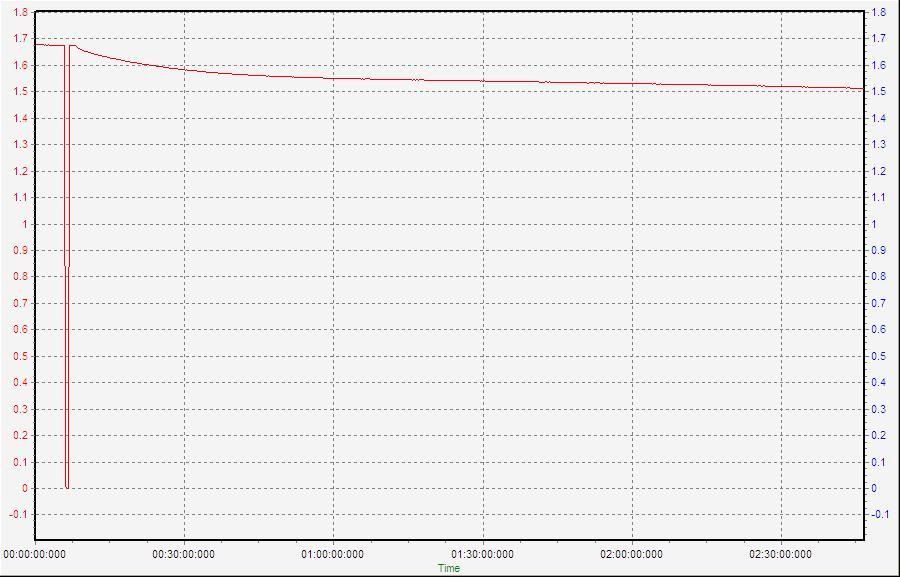
Here is an example showing a CBA III charge log of one of the cells AZVectrix sent me. On the other side are the notes showing the testing / reconditioning process. The graph shows a Vectrix cell coming back up "the cliff" after a controlled deep discharge to 0.5V at 0.5A (the reconditioning discharge is a bit like abseiling down the cliff rather than falling over the edge!):
The Prius SMR is one of the System Main Relays from a Japanese MK1 Prius battery. A chunky contactor allowing me to automatically switch off the load on the battery according to the time set on a mains timer. The mains timer just turns off the 12V supply to the SMR, which then turns off the discharge process. I calculate how long it will take to discharge the battery, set the timer to a shorter time than that, record a graph (or, so far, just record the minimum pack voltage). I have so far used a fairly low discharge current, like 400W globes causing 1.35A discharge current on a 120s NiMH battery. Once the pack is getting close to empty, I reduce the load further, until the first cell reverses. This reversal I had to measure with a DMM, manually, so far. Measuring 20 modules of 6 cells is time consuming and dangerous because there is potential for touching exposed 150V terminals. So I would prefer to just look at the computer monitor instead of recording 20 module voltages repeatedly.
The first part of the discharge could run unobserved. If the cells were all fully charged before the test, then any cells reversing early on would not be able to be salvaged, anyway. But the recorded graph would show that empty cells are present.
It would of course be very nice to have a gizmo that automatically does the switching off when a voltage drop is detected. Software and / or IC wizardry would be required to make one.....
This information may be used entirely at your own risk.
There is always a way if there is no other way!
Unfortunately the CBA III will not work as hoped.
The reason is that it has only 10kOhm resistance when used as charge monitor. The 1MOhm resistors do not let sufficient current pass to let it have a realistic voltage measurement. The CBA III measures 0.8V when it should be about 55V!
And there is another issue with the voltage divider using 3 x 1MOhm resistors: That is too close to the impedance of a DMM (typically 10MOhm) and causes considerable measurement error! Once the DMM is connected, it is in effect a 1Mohm - 0.909MOHM - 1MOhm voltage divider.
I do not want to use a 10kOhm - 10kOhm(CBA) - 10kOhm voltage divider, because it will cause 0.5W heat to be generated across a 10kOhm resistor at 55V. I assume that is why the CBA has the 55V limit.
So it's back to the 'scope plan.....
This information may be used entirely at your own risk.
There is always a way if there is no other way!
Voltage drop of 1.2V at 144V will be *just* detectable with the PoScope monitor!
Here is a screenshot of a recording made with a x100 probe.
Y-achsis shows Volt x 100.
X-achsis shows minutes.
The recording was started when the 120s NiMH pack was being charged at 0.3A, then the charger was removed.
There are 10 visible steps in the voltage curve, representing a drop from 169.9V to 166.2V.
A 1.2V drop due to a single cell dropping to zero V would show up as 3 or 4 steps within a minute or so!
This information may be used entirely at your own risk.
There is always a way if there is no other way!
Here are the PoScope recorder results for a complete discharge of a 120s NiMH battery (Prius NHW10 half-pack, 6Ah or 6.5Ah).
This half-pack is just fine, although it has been left deeply discharged for over a year, maybe several years.
The absence of a single bad cell makes it difficult to be certain about the methods ability to detect a single cell dropping to zero volt. When the first cell dropped to zero volt during this discharge, the average cell was down to about 1.1V and the overall discharge curve was beginning to drop off steeply. Many cells, if not most, were getting close to the point where they would drop to zero volt if the discharge had continued.
That makes it very difficult to spot the small sharp drop from a single cell. It gets hidden in the overall drop of the curve. A cell that has much lower SOC than the others would be easier to spot, because the 1V drop would occur on the much flatter middle part of the pack discharge curve.
However, the rule of "three visible steps down on the screen display within one minute means one cell is empty" got me to exactly the right result, anyway! Sheer luck!?! I stopped the discharge when 1 cell was at zero volt.
Y-achsis: volts x 100
X-achsis: h:min;s;ms
I cannot show the entire graph in one frame. Here is the first half:
The first half shows:
5min of pre-recording;
brief disconnection of measurement cables to adjust something and check zero calibration;
reconnection of cables followed soon by commencement of discharge.
Discharge parameters:
First part timer limited to 4hrs.
4 light globes in series make up the load; their rating is 100W @ 240V AC.
This results in a slowly falling discharge current; it started with 1.35A, fell to 1.33A after a minute, down to 1.28A after 2h:40min. At the end it was 1.19A, shortly before I terminated the discharge.
I figure (Pi x thumb...) that about 6.1Ah were drained during the entire discharge.
The second half of the graph shows:
- the last 1.5hrs of the first 4hr part of the discharge;
- a 15min break (with voltage recovery) between automatic timer termination and manual recommencement of charging;
- recommencement of charging as before, with a 1hr timer limit;
- termination of discharge after about 45min (manually);
- voltage recovery of the pack for another 15min.
The third screenshot shows the manual termination of charge in much more detail:
The single steps are much easier to see, as is the fact that 3 steps per minute had just been reached.
During the last minute of the discharge ( 1.19A ) I manually checked the voltages of all 20 6-cell-modules in the half-pack:
The negative voltages are due to the measurement process and help to check that I measured them all):
21 6.67
22 -6.72
23 6.67
24 -6.81
25 6.78
26 -6.84
27 6.86
28 -6.75
29 6.79
30 -6.65
31 6.13
32 -6.63
33 6.72
34 -5.54
35 6.63
36 -6.63
37 6.70
38 -6.73
39 6.87
40 -6.90
When I had tested them 10 min earlier (also part of the third graph shown), they had all been balanced.
Next, I will reduce the discharge current and turn it into a reconditioning discharge for the weak strings 34 (and 31).
This information may be used entirely at your own risk.
There is always a way if there is no other way!
Am I missing the point?
This topic is very interesting, however, I think that there is the danger of missing the point.
The start of all of this was the Vectrix battery's failings and these failings were duly attributed to the cells becoming seriously un-balanced (as regards their state of charge) resulting in reduced range, cells being damaged, sometimes irrecoverably, through reverse charge during deep discharges etc, etc.
The problems of returning the battery to a state of 'balanced' cells has largely been overcome by the 'new' Vectrix software (of Oct / Nov 2008) or by the occasional use of the Freddy equalising charger.
Of the two solutions, the use of the Vectrix's own charger using the 'new' software, the likely result will be a reduction in the over life of the battery caused by excessive charge rates when nearing full (and also during it's inbuilt equalising charge) and the resulting battery internal heating and consequent damage.
The manual termination of the Vectrix's built in charge process (at around 80% full and the use of Freddy to complete the equalising charge may well prolong the life of the Vectrix battery.
The ideal solution to the problems caused the inept programming of the Vectrix charger, is to reprogram the charger whereby the correct charge process would always take place. THIS option is not available to us by virtue of the reluctance of the Vectrix organisation to allow us access to the software information / coding.
Now the diagnosis of the faulty battery/ faulty cells.
First test is a voltage check under specified conditions. The voltage of a full battery in good condition is the starting point.
The ability of the battery to provide it's Ampere Hour capacity (in full) using a specified discharge current over a specified time and ending at a specific voltage, would be the next check. If the battery can satisfy these two tests then it is in serviceable condition.
A battery which fails either (or both) of the above tests is unserviceable and is in need of maintenance or replacement.
Assuming that the battery fails the above test(s), An equalising charge should be carried out and the tests repeated. This will sort out the 'unbalanced' batteries from the genuinely faulty ones.
If the indications are still of a faulty battery then further testing can indicate which cell(s) is/are at fault and this is where I believe we are at on this current topic.
On 'Reconditioning cells' The impressions being given are that faulty cells can sometimes be 'reconditioned'. This is not strictly correct. 'Faulty' cells which have stood for a long time and/or lost capacity through lack of use, can be put through a number of charge / discharge cycles and this process will often 're-activate' the cell and bring it back up to a serviceable condition.
However, if a cell has 'lost' any of it's active chemicals through physical loss or an irreversible chemical reaction, then it will never be anything but sub standard and, arguably, unserviceable if it is intended to be used in series with 'good' cells
The previous post, by Mik, is of a Prius battery and, by what I understand, this battery is a 6.0 / 6.5 A/H which has been standing unused for some time.
To accept a full charge and to be able to provide 6.0 A/H on a discharge test indicates that this battery is in serviceable condition. The fact that some cells or cell groups are 'empty' and dropping voltage before others is normal. The remaining test is that the battery can supply current at the required (high) discharge rate, again as per manufacturers specification. If all of these test results are satisfactory then the fact is that this battery is fit for service and that is all that matters.
Although it would be nice if all of the cells lost voltage together (that is to say that they are all perfectly matched) this is extremely unlikely in a battery of any age other than brand new.
That the individual cells, which are 'weaker' (have a lower capacity than others) can be identified is very useful when dealing with a 'faulty' battery but is otherwise unnecessary.
I hope that the above notes will clarify the issues at hand which appear, to me anyway, to be getting very complicated.
Back to the current project.
Mik's methods of locating the elusive, relatively small volt drop in the large battery output voltage is only one of many ways of achieving the same result.
The use of any four digit voltmeter will easily show a volt drop of as little as 0.1 volts.
There is no need for oscilloscopes or other expensive data / voltage logger systems. (Indeed, the digital oscilloscope shows 'steps' of voltage drop when the drop is actually analogue. This can be misleading).
The absolute requirement is for a means of 'noting' a sudden (or at least a fairly rapid) volt drop of about 0.2 / 0.4 volts.
Again, I intend this information to be helpful. I will continue to look for a simple solution to the problem and when I have it I will share it on this forum.
Keep working, keep smiling and above all, Keep It Simple
The Laird
The USB scope which I use was cheaper than the cheapest DMM with computer link and data logging function. That's in the shop (Jaycar). The USB scope I bought via ebay from China was even cheaper but broke on day one. With a simple DMM one would have to sit and watch the entire time, as opposed to checking the graph every hour or so for signs of an empty cell.
Treatment of a known battery is a different matter - the subject here is how to identify if a battery is OK or not, with as little effort as possible.
I still have 2 Prius batteries of 240 cells each, which I have not even started with! It will save me a lot of time in the long run to establish a test procedure which only requires operator input a few times a day. And the Vectrix 102s NiMH battery is sufficiently similar to these ones to be analysed in a similar way.
Once I get my hands on a used Vectrix with battery problems, I'll know how to tackle the battery in the most efficient way.
Cells that cannot produce high currents will get so hot during normal riding that they will also suffer capacity loss, which can hopefully be detected with these simple methods.
This information may be used entirely at your own risk.
There is always a way if there is no other way!
Here is the PoScope recorder graph for the continuation of discharge for the same Prius battery half-Pack (BC HP2):
This was done by removing the 4x 100W rated globes with a single 25W globe (rating for use with 240V AC).
It resulted in a discharge current of 0.08A, or C/75. The equivalent for a Vectrix pack would be a discharge current of 0.4A .
I set the timer to four hours and left it alone.
When I checked 6-cell-module ("Stick") voltages after almost 4hrs, I found that 3 sticks had a voltage indicative of a single 0V cell.
I added a picture (lower down) with arrows added to the discharge graph to show where these cells were most likely dropping to zero V.
You can try to spot it on this graph first:
Here are the markers:
The spotting of a (pre-)reversing cell is trickier at such a low discharge current; the discharge graph is often not a typical "knee" or "Cliff" shape under such conditions. Sometimes it is more linear, or irregular in some way. At higher discharge current a single cell seems to always show the knee or cliff (I'm sure there are exceptions - I'm talking about relatively serviceable NiMH cells here).
This information may be used entirely at your own risk.
There is always a way if there is no other way!
.
.
.
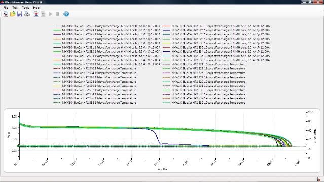
It turns out that this Half-pack was not fine:
I did a 19 day self-discharge test with individual stick capacity testing at 12A to 5.4V cutoff level.
Stick Nr 34 showed as clearly damaged in this test, but all the others were fine:
Clearly, that stick has a bad cell in it! But only the self-discharge test showed it this clearly. It might have shown up on a high current discharge test or an IR test as well - now that I have a "bad" stick to play with I might be able to determine this with some certainty!
The first half-pack out of the battery passed the self-discharge test; it seems that this 240s battery really has just one single bad cell in it!
...
...
Back to the Vectrix battery testing: TheLaird has sent me a schematic for an automated circuit which will terminate discharge when a 1V drop over 1min is detected - but I have not had any time to build and test it.
I have however used my PoScope in recorder mode for the discharge of the Vectux battery after 3 weeks of self-discharge rest. This was to determine if this is possible and if I have other cells with issues in the pack (other than the ones I know are bad - unfortunately it looks as if this might be the case; more about that later.)
Because I know the weakest cell in the Vectux pack, and because I can monitor it's voltage through the M-BMS, I was able to verify the detection method for a single cell dropping to zero volt in a 102s string.
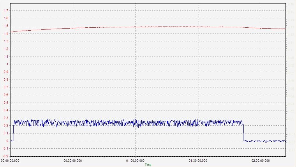
Here is what the PoScope graph looks like at the point of cell 103-003 dropping over the edge of the discharge "cliff":
Quite clearly visible! Pack voltage drops from 123V to 122V and discharge current from 1.13A to 1.12A over about 1 min.
Channel A: RED : Volt x 100
Channel B: BLUE: Discharge current in Ampere x 1/10 (voltage measured via a 10Ohm shunt = 1/10th of shown number)
This information may be used entirely at your own risk.
There is always a way if there is no other way!
OK, end of the theory part - I finally have a complete (used) VX-1 NiMH battery to test! It is probably in good order, but I know how much drama it is to take it all apart again, so I will try to test it thoroughly with little effort...HAHA! We'll see how long it takes this time....
This information may be used entirely at your own risk.
There is always a way if there is no other way!
Inspection showed that the batteries is in good condition. No transport damage visible. I found several rubber plugs the likes of which I had never seen before: I think it means they were missing in the original battery of my "Vectux". These plugs close the gaps between the three layers of the plastic container for the cells. They do however not really matter much, because the three layers are taped together anyway, which is sealing them better than the plugs would. I guess the tape around the batteries was introduced because these plugs kept falling out - just guessing though.
There is surface rust on most of the Inter-cell-connector (ICC) bolts of the rear battery top layer, but almost none on the front battery top layer ICC bolts. I have not peeped into the lower layers yet; it might just be the top layer and I don't know why. Once basic testing is done I will have to take off the worst affected ICC bolts and have a look if this rust goes down towards the threading and the contact area between cells and ICCs. And apply some corrosion inhibitor to stop it from progressing. I wonder if this could have been caused by condensation of moisture on the (cool) batteries during charging in warmer and humid conditions? If that's the case, the bottom layers might be affected more than the top layers. Has anyone else seen such rust on a Vectrix battery? Does anyone know what causes it and how to best stop it?
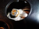 CLICK TO ENLARGE.
I tightened the ICC bolts in the top layer because I was told by the previous owner that some had been removed but had not been properly torqued up upon re-installation. Good tip - some were very loose, indeed!
.
.
Only other thing worth mentioning is that there are a few marks on the Andersons connector pins (front surfaces): Probably from re-connecting the battery without an ICL. I think this does not matter, because this damage to the connector happens at the front of the connector and that part is not making contact when it is completely closed. Clever design! This does not matter if you buy just a battery, but it might matter if you buy an entire VX-1. There is no easy way of knowing if the marking on the Andersons connector occurred when the presently installed fuse was already in the scooter. However, the capacitors on the motor controller can apparently also get damaged by inrush current. I have no idea if this would be an "all-or-nothing" event, or if the capacitors can suffer cumulative damage similar to the fuse - and then suddenly fail later on for no apparent reason.
This information may be used entirely at your own risk.
There is always a way if there is no other way!
Here are the open voltage measurements after I received the battery.
It had been completely discharged for transport purposes.
The measurements shown below can all be made without removing the battery from a VX-1.
I deduct that three cells in the front battery were at close to zero volts - and all the cells in the rear battery were at normal voltage.
(All cell numbers relate to Nr.1 being the cell at the negative battery end):
.
.
Initial voltages:
.
Entire Front battery:50.00V
Module 4: 7.83
Cell 28: 1.144
Cell 29: 1.10
Cell 30: 1.15
Cell 31: 1.08
Cell 32: 1.13
Cell 33: 0.0056
Cell 34: 1.09
Cell 35: 1.09
.
.
Modules 4,5,6+7 together: 33.29V (likely 2 more low cells.)
.
.
Module 9: 8.87V
Cell 75: 1.09
Cell 76: 1.088
Cell 77: 1.096
Cell 78: 1.085
Cell 79: 1.086
Cell 80: 1.123
Cell 81: 1.128
Cell 82: 1.124
.
.
Entire rear battery:
.
Module 1: 9.92
Cell1: 1.124
Cell2: 1.096
Cell3: 1.091
Cell4: 1.081
Cell5: 1.073
Cell6: 1.097
Cell7: 1.075
Cell8: 1.109
Cell9: 1.139
Modules 2+3: 19.93.
Modules 10+11: 19.87
Module 12: 9.79
Cell94: 1.097
Cell95: 1.098
Cell96: 1.084
Cell97: 1.083
Cell98: 1.075
Cell99: 1.081
Cell100: 1.073
Cell101: 1.079
Cell102: 1.089
.
.
Both batteries plugged together: 109.2V .
.
.
Maths:
1.1 * 99 = 108.9 (again supporting 3 empty cells in front pack).
.
.
Front pack: 50V/47=1.06V per cell if only cell Nr 33 is at zero V.
but more likely, (because all good cells are around 1.1V) you get this: 1.11*45=50V - meaning that there are (48-45=3) cells with zero volts in the front battery.
.
.
Rear pack: 1.1* 18 = 19.8
1.1 * 9 = 9.9
That means all cells in the rear pack are having good voltage.
.
.
.
After these measurements I put the battery on a few hours of "Freddy" charging to see how the zero-volts cells recover.
This information may be used entirely at your own risk.
There is always a way if there is no other way!
I hadn't noticed the damage on the andersons before....I haven't hooked that pack up without first precharging the controller caps, however, Vectrix Australia could have done so.
I have since accidentally hooked up my MC to a fully charged battery, it survived (with some ozone).
I'll let you know if the caps die for no apparent reason :)
the rust on the top bolts in the rear could have been the result of water ingress earlier in the year.
I rode through a ~100mm deep puddle at 80kmh.
enough water made its way at high enough pressure to cause the temp sensor boards to stop reporting (until they dried out).
My display light up like a christmas tree at the time, and the charger stopped working.
all was well after a few hours, but thats probably why you are only seeing rust on the rear battery.
I hadn't actually noticed it before.
re rust inhibitor (potassium acid, or was it nitric acid, I forget)....I would suggest something along the lines of noalox for the electrical contact area.
same keeping the water out quality, but better conductivity.
This is the stuff im talking about (im sure its available elsewhere aswell):
http://www.evworks.com.au/index.php?product=BAT-NOA8OZ
Matt
Daily Ride:
2007 Vectrix, modified with 42 x Thundersky 60Ah in July 2010. Done 194'000km
Hi Mik et al,
The rust on terminals. Yes, I have seen it before and it was due to saltwater ingress prior to the 'holes' in the front frame being covered with tape. The saltwater could have been sea spray on the roads or salted roads during freezing roads conditions.
Clean off the rust and apply a little lanolin / vaseline / petroleum jelly and all will be well.
Capacitor failure, is usually due to a dielectric breakdown through the application of excess voltages (transient voltage 'spikes' etc). With very high value, low internal resistance types (the type that the Vectrix has) the capacitor can be damaged by the sudden application of high voltage. This causes excessively high current to flow into the capacitor and the connecting leads simply burn out. Damage is usually instantaneous and irreparable. It is unlikely that the capacitors would fail in use because the currents in and out of the capacitor (when in use) would be very considerably less than the connection surge mentioned earlier.
Back to the original topic, identifying a battery with faulty cells/ damaged battery.
I have read many of the posts and given the matter some thought. It has occurred to me that we should step back and consider some older strategies. With lead acid batteries, the test for a 'faulty' battery was to place a high current resistor accross the terminals and observe the voltage. If the voltage dropped within a few seconds OR the voltage was low generally, then the battery was 'unfit for service'. The battery would be given a charge to 'fill it up' and the test was again applied. If the voltage dropped again within a few seconds, then the battery was condemned as unfit for service and had to be replaced.
Now, applying the same idea to the Vectrix battery, we have a battery of which we know the terminal voltage and the internal resistance. We know the open circuit voltage at full charge and we can calculate the volt drop at the terminals when a known load ( fixed/known resistance) is applied. We also know that if any cell(s) is/are not 'up to the job' there will be additional voltage drop. Preliminary calculations produce the following results.
(using a Cell resistance of 0.0012mOhms)
102 cells will drop 0.1224 volts per ampere of discharge.
At 10 amperes discharge the volt drop will be 1.224 volts.
At 20 amperes discharge the volt drop will be 2.448 volts.
At 30 amperes discharge the volt drop will be 3.672 volts.
This pattern continues.
If a faulty cell is present or if the battery is in a low state of charge, then the volt drop will be greater than expected.
For every cell which is empty there will be an extra drop in the voltage.
Therefore what is needed is a simple way to load the battery with a fixed resistance and a means of measuring the relatively small voltage drop without the other 125 or so volts obscuring our view. This is not as difficult as it sounds and I already have a circuit design which could make the required voltage drop easy to observe.
The difficulty with this method is in the application of the resistive load. One way of doing this which might work is to apply the brakes and use full throttle to give a fixed current drain on the battery. One would need to know a) that the Motor control unit would not be damaged by this (it shouldn't as it is only a stalled take off and would only last for a few seconds) and b) exactly what current would this draw from the battery.
If anyone thinks that there is something here of interest, then I will produce working drawings of the circuit I have in mind and you/we can give it a whirl.
have fun folks,
The Laird.
Thanks for that! Do you think it is necessary to take all the ICCs off and / or check the lower two levels of cells as well?
Good to know, thanks again!
That is definitively of interest! But there might be an easier way, and I guess that is what Vectrix do with the "Memory dumps" sometimes mentioned.
Because I figured out some of the CANBUS messages we might be able to "calculate" many battery parameters from the measurements done by the bike itself!
http://visforvoltage.org/book/ev-collaborative-hand-books/6916#comment-40745 has the necessary details, namely:
Time; speed; throttle position; current draw; and battery voltage.
.
.
Can anyone please work out how to feed the data from the post http://visforvoltage.org/book/ev-collaborative-hand-books/6916#comment-40699 , showing a full throttle Vectux acceleration, into a spreadsheet program?
If we can figure out how to efficiently import data from the CanHacker program into a spreadsheet program, then we can draw the most informative graphs that tell us a lot about a battery!
Even the 1V drop caused by a single cell reversing would be visible on these graphs, given the right conditions.
This is exiting!
Those computer whiz-bangs among the silent crowd, please work out how this:
50.600 00FEF74C 8 00 00 8A 00 00 00 00 8A B1/4By3+8:GO:Vlt;BY5:CP=68;CC=1C;tr+EC=0D
50.600 00FEFC4C 8 D1 00 40 46 CF 35 9A 3D B1/4 FE 00 40 46 xx xx FA/B/C 4A
50.600 00FF0A4C 8 00 00 00 78 00 00 12 14 B1/4 5x00;By4=8x;By7=1x,By8=1x;EC:By7+8=TempSensor with delay
50.610 00FEFD4C 8 88 00 00 00 00 00 00 0E B1/4 6x00; Byte1=88, BYTE8=1x
50.610 00F00300 8 2E 02 14 30 30 79 00 49 B1/1 By1+2+5=THROTL;By4=BRKE+KILSW+SIDSTAND;By6+8=?timers?
50.610 00FEF105 8 00 00 62 00 5A 00 88 5A B1/4 By3=SPEED;By5+8=AMP;By7=VOLT
50.610 18FEE617 8 0F 06 1A 00 01 01 34 00 B1/47 Hr/min/sec/00/01/01/Lightsensor/00
50.610 00F00300 8 1B 02 14 30 1D 7A 00 4A B1/1 By1+2+5=THROTL;By4=BRKE+KILSW+SIDSTAND;By6+8=?timers?
50.610 00FF0F00 8 84 00 00 00 31 30 30 37 B1/4.2 HEADLIGHT + INDICATORS
50.610 00FEEFF9 8 00 00 00 00 00 00 00 55 B1/40?Charger/voltage? active charging D
50.720 00F00300 8 17 02 14 30 19 7B 00 4B B1/1 By1+2+5=THROTL;By4=BRKE+KILSW+SIDSTAND;By6+8=?timers?
50.720 00FF0505 8 15 01 61 27 21 22 1F 00 B1/4 12 00 00 1x 14 1x 1x 00
50.720 00F00300 8 16 02 14 30 18 7C 00 4C B1/1 By1+2+5=THROTL;By4=BRKE+KILSW+SIDSTAND;By6+8=?timers?
50.720 00FEF74C 8 00 00 8E 00 00 00 00 8E B1/4By3+8:GO:Vlt;BY5:CP=68;CC=1C;tr+EC=0D
50.720 00FEFC4C 8 D1 00 40 46 CF 35 9A 3D B1/4 FE 00 40 46 xx xx FA/B/C 4A
50.720 00FF0A4C 8 00 00 00 78 00 00 12 14 B1/4 5x00;By4=8x;By7=1x,By8=1x;EC:By7+8=TempSensor with delay
50.720 00FEFD4C 8 88 00 00 00 00 00 00 0E B1/4 6x0
can be imported into a spreadsheet program!
I'm talking about a fast and automatic process - which can turn the entire data stream of a charge or discharge into visual graphs without much manual typing.
This could become the first truly open-source piece of "Vectux" software - it does not rely on any copyrighted stuff!
This information may be used entirely at your own risk.
There is always a way if there is no other way!
Back to the progress on the battery being tested:
After finding that three cells in the front battery were at close to zero volts, I charged the battery with "3 u-Freddy" for about 8 hrs.
Results: The zero-V cells became indistinguishable from the rest of the pack within a few hours of 0.15A charging.
Voltages after about 9 hours @ 0.15A charge:
.
Module 4: 9.83
.
Cell 28: 1.231
Cell 29: 1.217
Cell 30: 1.246
Cell 31: 1.214
Cell 32: 1.235
Cell 33: 1.215
Cell 34: 1.222
Cell 35: 1.216
.
Modules 5,6,7+8 together: 39.08
Calculation: 39.08 / 4 = 9.77V average for inaccessible front battery modules.
.
Module 9: 9.82
.
Cell 75: 1.216
Cell 76: 1.221
Cell 77: 1.223
Cell 78: 1.218
Cell 79: 1.214
Cell 80: 1.228
Cell 81: 1.227
Cell 82: 1.232
.
.
Module 1: 11.05
.
Cell1: 1.225
Cell2: 1.220
Cell3: 1.222
Cell4: 1.223
Cell5: 1.226
Cell6: 1.222
Cell7: 1.222
Cell8: 1.221
Cell9: 1.227
.
Modules 2+3: 22.04
.
Modules 10+11: 22.06
.
Module 12: 11.01
.
Cell94: 1.217
Cell95: 1.216
Cell96: 1.217
Cell97: 1.218
Cell98: 1.224
Cell99: 1.221
Cell100: 1.229
Cell101: 1.214
Cell102: 1.216
.
Both batteries plugged together: 124.6
.
.
After that very gentle initial charge, I had to leave the battery alone for a week.
During that week I thought about the IDeA (Imbalance Detection Apparatus) and so I started using measurements of IDeA segments 1, 2 and 3 from then on.
The 3 IDeA segments are equal sized parts of the battery, 34 cells each.
.
.
The following are the measurements after 7 1/2 days of rest at about 20degC:
Entire battery: 121.6
.
IDeA segments:
1: 40.71
2: 40.57
3: 40.66
.
Module 4: 9.58
Modules 5,6,7+8 together: 38.18
Module 9: 9.60
.
Module 1: 10.77
Modules 2+3: 21.55
Modules 10+11: 21.54
Module 12: 10.70
.
.
I measured the other accessible modules as well, just to be sure; but over the following week I was able to verify that the IDeA voltages are usually sufficient to determine if there is any imbalance. A very quick and easy way to check for pack imbalance!
This information may be used entirely at your own risk.
There is always a way if there is no other way!
Once it was established that the battery - including the cells initially at zero Volts - was holding voltage well, I proceeded to charge it up completely:
I started with a "8-u-Freddy" charge while I was working on the re-build of my "Universal Freddy" for higher currents. It takes too long to charge the battery from empty with an 8 uF motor-run capacitor (the original "Freddy") at about 0.3A. It would take 100 hrs at least, but probably double that due to charge inefficiencies which are higher at low currents.
Charge start:
Freddy 8uF
Timer 24hrs
123.8V after about 2 min\
23.3degC ambient, falling
24.9degC max all over battery
Measurements at 30min:
Entire peak V: 128.4
Actual present current (A): 0.34
.
Measurements after 13.5 hrs:
Entire peak V: 138.5
Actual present current (A): 0.32
Temperature:
Ambient: 22.4
Max IR at battery: 23.4
IDeA segments:
1: 46.28
2: 46.23
3: 46.31
Measurements at time: 22hrs:
Entire current V: 139.7
Actual present current (A): 0.32
Temperature:
Ambient: 23.7
Max IR at battery: 24.0
IDeA segments:
1: 46.65
2: 46.63
3: 46.69
.
.
After 22.5hrs of this 0.3A charging I had "Universal Freddy" ready again. Ah gone in until disconnect: 22.5h * 0.33A = 7.4Ah
Charging with New UFreddy from here on:
Full bore = 58uF results in 2.43A @ 139.8V
I charged for a couple of hours at maximum current of ~2.4A, then reduced it to 1A for overnight charging. During the day I turned the charger off while at work.
Then I connected my logging PoScope the next evening to get better recording of what is happening.
Entire open V:140.1
Actual present current (A): 0; then start at 2.43A
IDeA segments: Few minutes after start:
1: 47.05
2: 47.06
3: 47.10
Temperature:
Ambient: 20.6
Max IR at battery lid: 21.5
1845pm: Restarted same settings DTimed 2hrs.
Total max Ah gone in so far: 21Ah + 8.4Ah = 29.4Ah
Charge rate reduced to 8uFreddy = 0.3A for overnight charging.
PoScope continuing to run.
DTimed for 10hrs.
Measurements at time: early am:
Entire peak V: 143.8
Entire current V: 143.8
PoScope (V): 145
Actual present current (A): 0.3A
Temperature:
Ambient: 19
Max IR at battery top cover: : 23
38.7Ah so far.
Increased to max 2.35A for couple of hours, then turned off for the day.
Measurements at 2010-10-01, evening: before start of last charge stage:
Entire present V: 141.8DMM ; 141.3CDMM; 142PoScope
IDeA segments:
1: 47.19
2: 47.19
3: 47.21
Temperature:
Ambient: 20.3
Outer battery case: 23.3
Max IR down into battery without plastic cover: 26.4 front; 25.8 rear
Start charge at 58uFreddy 1735pm: 2.45A start
Measurements at time: 1840
Entire peak V: 148.6DMM / 149PoScope
PoScope (V): 149
Actual present current (A): 2.3
IDeA segments:
1: 49.35
2: 49.30
3: 49.36
Temperature:
Ambient: 20
Outer battery case: 23.5
Max IR down into battery without plastic cover:
Front: 28
Rear: 28
1hr left on timer - continue
Measurements at time: 1940 (15min post turnoff)
Entire peak V: 148.7
Entire current V: 146.1
PoScope (V): 146 / 149 peak
Actual present current (A): 0
IDeA segments:
1: 48.57
2: 48.49
3: 48.56
Temperature:
Ambient: 20
Outer battery case: 27.6
Max IR down into battery without plastic cover:
Front: 36
Rear: 36
46.9Ah total gone is so far.
.
.
Final, slow 8uF topup charge for about 12hrs: This also serves to show the behaviour with the 8 uF Freddy charger when used for it's design purpose: An EQ charge topping off a battery already filled by a faster charge process.
0.3A / 8uFreddy DTimed 14hrs.
Measurements at 1h:10min :
Entire peak V: 145.7
Entire current V: 144.7 (still falling from the earlier 2.4A charge)
PoScope (V): 145
Actual present current (A): 0.3
IDeA segments:
1: 48.11
2: 48.02
3: 48.11
Temperature:
Ambient: 20
Outer battery case: 28
Max IR down into battery without plastic cover:
Front: 36.9
Rear: 36.7
Measurements at 6hrs:
Entire V: 144.5
PoScope (V): 145
Actual present current (A): 0.3
Temperature:
Ambient: 20
Outer battery case: 25
Max IR down into battery without plastic cover:
Front: 33
Rear: 35
Temperatures have fallen despite ongoing charging and voltage has stabilised.
.
.
Measurements at 12hrs:
Entire peak V: 145.0
Entire present V: 144.9
PoScope (V): 145
Actual present current (A): 0.3
IDeA segments:
1: 48.24
2: 48.17
3: 48.24
Temperature:
Ambient: 19.5
Outer battery case: 26
Max IR down into battery without plastic cover:
Front: 31.7
Rear: 32.8
Turned off after this.
50.5Ah total gone in.
.
.
This was then followed by the first discharge with monitoring for single cell reversal.
I am not sure why the IDeA segment 2 is around 70mV lower than the other two at full charge.
The 0.3A charge from the original Freddy design with 8 uF capacitor causes a mild degree of warming only. About 12degC above ambient without any active cooling. However, the ventilation on the garage floor is bound to be a lot better than inside the Vectrix battery compartment. It might heat up more inside the scooter - but that is very easily controlled by running the cooling impellers.
This information may be used entirely at your own risk.
There is always a way if there is no other way!
Now to the discharge capacity test of the battery (done just after finishing the charge):
Measurements at time: before start:
Entire V: 143.8CDMM
PoScope (V): 145
Actual present current (A): 0
IDeA segments:
1: 48.07
2: 48.00
3: 48.07
Temperature:
Ambient: 19
Outer battery case: 26
Max IR down into battery without plastic cover:
Front: 31
Rear: 32
Measurements at time: Just at start:
PoScope (V): 145
Actual present current (A):
CDMM6.1
DMM across shunt: 6.1
PoScope: 6.3
4 x 400W Halogen heater elements and 1x 100W globe results in 6A discharge current.
Measurements at time: 0833am / 20min record
PoScope (V): 138
Actual present current (A):
DMM across shunt: 5.89A
PoScope: 6A
IDeA segments:
1: 45.76
2: 45.68
3: 45.75
Plan is to add another 100W globe when current drops to 5.8A
.
.
Measurement of cell voltages to figure out why the IDeA segment 2 is 70mV lower than the others:
(All values in Volts; At beginning/At end of measurement during discharge)
Entire battery: 135.1/134.5V
5.85A/5.84
IDeA segments:
1: 45.15/44.97
2: 45.08/44.91
3: 45.15/44.97
Module 4: 10.60
Cell 28: 1.319/1.316
Cell 29: 1.320/1.317
Cell 30: 1.318/1.316/
Cell 31: 1.321/1.319
Cell 32: 1.319/1.318
Cell 33: 1.320/1.319
Cell 34: 1.320/1.319/
Cell 35: 1.320/1.319
Module 1: 11.95
Cell1: 1.322
Cell2: 1.321
Cell3: 1.323
Cell4: 1.324
Cell5: 1.325
Cell6: 1.321
Cell7: 1.325
Cell8: 1.322
Cell9: 1.319
.
And another 16min later:
Entire battery: 133.3/133.2
IDeA segments:
1: 44.55/44.52
2: 44.50/44.46
3: 44.56/44.53
5.82A/5.81A
Module 4: 10.46V
Modules 5,6,7+8 together: 41.86V (41.86/4= 10.465)
Module 9: 10.46
The 70mV difference does not appear to be due to individual cells!
.
.
A further 100W globe was added to load to bring current back up when it had fallen to 5.8A after about 55min of discharge.
The current remained around 6.15A for the remainder of the discharge.
current gone to 6.26A DMM
.
.
Measurements at 4hrs:
PoScope (V): 128; DMM: 126.8
Actual present current (A): DMM across shunt: 6.13 PoScope: 6.2
IDeA segments:
1: 42.36
2: 42.34
3: 42.38
Measurements at 4h:32min:
PoScope (V): 126; 124.7 CDMM
Actual present current (A): DMM across shunt: 6.08 PoScope: 6.2
IDeA segments:
1: 41.69
2: 41.65
3: 41.70
Temperature:
Ambient: 20
Outer battery case: 26
Max IR temp down into battery without plastic cover (DegC):
Front: 28.7
Rear: 30
Measurements at 4h:43min: cell spotted zero-ing on PoScope graph (at abbout 4:44:30 in graph below)
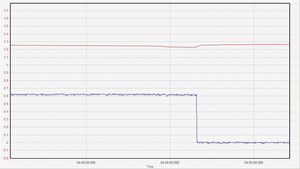
PoScope (V): 123/ CDMM 122.3
Actual present current (A): DMM across shunt: 6.06A? PoScope: 6.1A
IDeA segments:
1: 39.93V The reversing cell is located in IDeA segment 1!
2: 41.32V
3: 41.37V
The sudden drop by about 1.4V is clearly visible, as is the slightly delayed voltage recovery of cell 30 just a few seconds after the load was removed.
And it shows up like expected in the difference between the IDeA segment voltages.
.
.
Manually stopped discharge after 4h:44min after spotting the 1-cell drop in the graph above. That means around 29Ah discharged in total.
Measurements just after turning load off:
PoScope (V): 126; CDMM: 124.9
Actual present current (A): 0
IDeA segments:
1: 41.75 The reversing cell has immediately bounced back when the load was removed.
2: 41.74
3: 41.82
Restarted discharge 12min later to find the reversing cell:
Measurements during restart:
Actual present current (A): DMM across shunt: 6.2 falling to 6.02
IDeA segments:
1: 40.36/40.27/ 39.95 Rapid voltage fall in segment 1
2: 41.70/41.33
3: 41.72/41.36
Entire battery: 122.3V
Module 4:
Cell 28: 1.214
Cell 29: 1.214
Cell 30: -0.217 But this is not the cell that was at zero Volts initially!
Cell 31: 1.216
Cell 32: 1.199
Cell 33: 1.212
Cell 34: 1.212
Cell 35: 1.212
Module 1:
Cell1: 1.224
Cell2: 1.219
Cell3: 1.219
Cell4: 1.223
Cell5: 1.224
Cell6: 1.218
Cell7: 1.224
Cell8: 1.218
Cell9: 1.216
.
.
That concludes the discharge - followed by some inspection of the pack.
Close inspection of cell 30 revealed that it is laterally swollen - and it is the only swollen cell in the 4 modules in the top layer.
The 4 visible Celsidots in the top layer are all still white (meaning pack was never hotter than 60DegC).
The rusting of the ICC bolts is also present in the middle layer (maybe a bit less), but almost absent or absent in the bottom layer. This is all quite hard to see through the gap in the side of the container. I don't yet understand how this occurs.
The cells with visible stickers were produced in November 2006:
Module 4:
Cell 28:
C3008 061125 000263
Cell 29:
C3008 061125 000502
Cell 30:
C3008 061125 000559
bulging
Cell 31:
C3008 061125 000046 Celsidot white
Cell 32:
C3008 061125 000555
Cell 33:
C3008 061125 000070
Cell 34:
C3008 061125 000541
Cell 35:
C3008 061125 000509
This information may be used entirely at your own risk.
There is always a way if there is no other way!
Pages