Equalising batteries. - Principles of Equalisation
Background.
It is the case that during manufacture, there are cells variations which include internal resistance and internal leakage (of the charge). These two effects produce/cause the problem we know as imbalance, whereby during use, (both charge and discharge) the state of charge of cells in series, begins to vary cell by cell.
In all series connected batteries, when the state of charge between cells varies sufficiently, a deep discharge will result in those cells containing the lower charge to become 'empty' whilst the remainder of the battery still has a useful charge remaining. These 'empty' cells will become reverse charged if further current is taken from the battery.
Equalisation.
In series connected batteries the term Equalisation refers to the process whereby equality of state of charge of each and every cell is achieved.
The need for equalisation is brought about by the simple fact that not all cells are equal (there will always be variations in the manufacture of the cells) and because the cells are series connected and all receive the same charge as each other regardless of their losses (through use or leakage), imbalances in the state of charge of individual cells will eventually occur. To correct this, some means of compensating for this 'inequality' is needed.
Lead Acid batteries.
The Lead Acid battery is equalised by the simple expedient of 'overcharging'. In this process the battery is given a 'full' charge which is then followed by a further charge which is continued until all cells are 'full' as denoted by the specific gravity of the electrolyte.
This simple process is adequate and does no damage to the cells. During the 'overcharge' the cells 'gas off' i.e. they produce oxygen and hydrogen (electrolysis of water) and the lost water is replaced as required by 'topping up' the cells with distilled water.
As a side note. Lead acid cells are not damaged by reverse charging (cell reversal) as both plates (+ve and -ve) are basically lead.
Comparing Lead Acid with NiMH.
The NiMH cell is totally different from the Lead Acid cell in almost every detail. Lead acid are open to air and can be topped up. NiMH are closed and sealed and pressurised. Lead acid can be reverse charged NiMH cannot. Lead acid can be overcharged without damage, NiMH will build up excessive internal pressures if overcharged and can become permanently damaged.
[ Regardless of the above it is (common?) practice to try to compensate for imbalance of the NiMH cells by overcharging. Certainly in the case of the Vectrix charge process 'overcharge' is the norm and it occurs every 12 or so hours of use and the damage can be seen in the failed batteries and/or the bulging cells which are contained within most (probably all) Vectrix batteries.]
Equalisation methods/practices
The present method of equalisation was developed many years ago for early battery technologies (Lead Acid) whereby the 'overcharge' or 'equalising charge' did not effectively cause cell / battery damage.
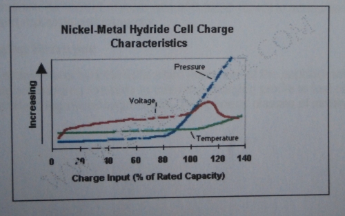
With modern battery technologies, equalisation by overcharge is totally unsuitable due to the potential damage which will be caused by even moderate overcharging. For the NiMH cell, internal pressure begins to build up after the cell reaches 90% of 'full'. There is a substantial pressure build up at 100% charge and at 120% charge, the pressure becomes dangerously high. see graph below.
The ideal method of equalisation of 'new technology' batteries is to monitor every cells voltage and to provide a means of varying the charging current cell by cell, whereby every cell of the battery is charged to full but no cell is overcharged. This is generally referred to as a 'battery management system'.
In the absence of a battery management system and in view of the cost and complexity of retro fitting such a system to the Vectrix, I have considered the possibilities of doing something different.
Logically, if you cannot safely equalise by overcharging, could it be possible to equalise by undercharging or discharging? What I am in process of doing is testing the following method of 'equalisation by undercharge/discharge'.
In Practice
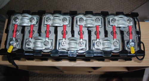
Equalisation by discharge can be easily achieved by permanently fitting a low value resistor (39.0 Ohms)to each and every cell, the value to be determined by available time for equalising and a practical rate of discharge (not too fast that it would empty the battery in too short a time span).
When the battery begins to show a 'lack of range'/'loss of capacity', it is discharged to it's lowest practical level and left to complete 'equalisation' i.e. to run completely flat (as in 0.1 volts per cell). When this is achieved, the battery is then recharged. Universal Freddy would bring it back up to 100 volts in a half hour or so and then the Vectrix charger would take over the charge completion.
Th result of this would be that all cells would now have an equal state of charge unless there were faulty cells, in which case no form of equalisation will succeed.
In a really bad case of imbalance, assume that some cells were at a 10% difference in state of charge, from battery 'empty', some cells empty and others at 10% charge, it would take 5 days to completely empty/equalise the battery. In practice 1 day for every 2% of imbalance.
This unusual method of equalisation will never reverse charge a cell nor will it ever overcharge a good cell. This method of equalisation has been undergoing tests on two eight cell sections of Vectrix battery for the past few weeks. Results to date are good, one of the two sections had cells voltages ranging from less than 1.0 volt up to 1.31 volts at the start of testing, after the first equalisation discharge all cell voltage remained equal throughout a charge of 30 A/H and remained equal throughout a discharge of 26 A/H. These cells have retained their equal voltages throughout further charge Discharge cycles.
The second section has shown almost identical results and I now intend to build this system into my Vectrix battery (which is not very well at the moment and a battery rebuild will be a good time to incorporate this system).
There is a natural 'follow on' to this system. If the individual cell voltages differ, then they will also discharge (through the resistors) at different rates. Higher voltage cells will discharge faster than lower voltage cells. This results in an ongoing 'equalisation' which is taking place at all times. This could account for the equality of the cell voltages in the tests which have taken place so far.
The cells fitted with resistors are pictured below.
Before the doubters begin to whinge I will admit to the 'faults' of this system.
The cells are being permanently discharged at the rate of 26mA (at 1.0 volts) to 35mA (at 1.35volts) per cell.
There is a heat production of between 2.6 watts and 4.8 watts (whole battery) continuous.
The battery will 'run down' in 35 days from being fully charged with no useage.
A 'Universal Freddy' will be needed to begin the recharge process following every 'equalisation'.
However, the NiMH cells will not be damaged by the total discharge provided that it is not left totally discharged for extended periods of time. ( I have taken this information from Ever Ready's data sheet, they do not define 'extended' but I suggest that it refers to Months as opposed to Days/Hours).
Whatever else might be said about this radically different method of 'equalisation', it will never destroy a cell through overcharge unless that cell is already in damaged/faulty condition.
Further information is available from The Laird by personal message or on the forum.
Have fun folks, I am waiting for the comments / critisism.
The Laird :-)


Laird,
Great approach. Again looks like you have put in a great deal of work and intelligent thought into this process.
I do have a question. You state
"With modern battery technologies, equalization by overcharge is totally unsuitable due to the potential damage which will be caused by even moderate overcharging. For the NiMH cell, internal pressure begins to build up after the cell reaches 90% of 'full'. There is a substantial pressure build up at 100% charge and at 120% charge, the pressure becomes dangerously high. see graph below."
From my research I was of the understanding that pressure build up is from excess heat and the associated expansion. We know that as NiMH approaches full it converts more of the energy to heat. It is also my understanding that as long as the batteries are charged at a sufficiently low rate such that the batteries can dissipate the heat and not build pressure then this is an acceptable method of equalization.
This is what I did with the batteries in my Honda Insight. In this case I charged 4 subpacks at a time at a low rate( .5 Amp for a 6.5 ah battery ) while running a fan. Worked great for about 9 months till they got out of balance again. Maybe I need a freddie for my Insight...
My point being that the enemy is the heat and the symptom is the pressure. As long as as the heat is dealt with, via slow charging with your modified charging scheme or a freddie and running the fans, then would you not end up with safe equalization?
This does not address the other problems your system fixes, draining individual cells too low and damaging them and keeping them equilzied as you ride, which is something we could all use to keep our bikes on the road for much longer.
Todd
Hi The Laird,
again interesting starting point. I disagree in two points: I don´t think it´s good for the cells to discharge them down to 0,1v, and the emptier cell have a very fast voltage drop at the end of the discharge cycle, so I´m
not sure if the lower-Voltage-lower-dischargerate will count.
Maybe there is a simple and cheap solution? use a resistor and a normal silizium-diode in forward direction.
(Source:http://www.elektronik-kompendium.de/sites/bau/diagramm/02011131.gif)
The diode needs a voltage difference of 0,7v to "let" curent pass, and would start to inhibit the further discharge around this level of cellvoltage.
Maybe this would be a way?
Greetings Mike
Hi Todd,
You are right up to a point, the pressure build up is a result of two things one of which is heat the other however is tied into the recombination of the oxygen produced by the 'overcharge' current.
As I said, the graph is from some Ever Ready literature which I have and is based on a high charge rate and applies to that same high charge rate. What is interesting is that Duracell state that "Thus charge control is required to prevent the build-up of gases and pressure. Duracell recommends that continuous overcharge does not exceed 0.33%C for optimal performance".
Observations on the Vectrix batteries shows that pressure build up is common with the evidence being the 'bulged cell syndrome'. I think that you would be hard pressed to find a Vectrix battery which doesn't have any bulged cells.
All that I have to work on is the extreme figures quoted. In view of this I would suggest that all overcharge be avoided if possible and that would include the, so called, equalising charge of the Vectrix (original) programmes.
Incidentally, I designed the original Freddy as a means of providing a more realistic charge rate for equalisation in the absence of anything better. It was obviously not ideal but it was an improvement on the Vectrix system.
Hi Mikemitbike,
Yes I had considered the use of a diode and resistor combination. Thing is, there isn't much space, it adds to the cost and complexity and is more to go wrong.
In a failure condition, the metal film resistors will go open circuit (relatively harmless and very unlikely as the resistors used are rated at 0.5 watts but are only dissipating 0.05 watts maximum) Diode failure is usually short circuit and this would load the series resistor causing a failure and /or overheating of the resistor. It would also throw the equalising system out of balance with one cell being discharged at a much higher rate than the others.
The resistors used are 1% x 39 Ohms x 0.5 watts and very unlikely to fail in this application.
I hope that this all helps to explain my reasoning.
Keep smiling :-)
The Laird
Aah, the bottom-balancing vs. top-balancing debate again...
I found that deeply discharged Panasonic NiMH D-cells in the NHW10 Prius seem to be coping well with prolonged discharge to near-zero volt. But the question is what repeated episodes would do to a battery. Also, one such battery has subsequently developed problems (one cell failed with electrolyte leakage and zero V and many cells corroded on the outside) which might be related to this.
"Battery-University" makes some recommendations about NiMH reconditioning, which led me to the conclusion that ideally one would stop a reconditioning (very slow) discharge at 0.4V (at individual cell level). That worked well for the Vectux cells - but the more damaged the cell already is, the less beneficial effect it has.
I would certainly prefer to include a diode like Mikemitbike suggests, not sure what voltage would be best to use as the stop point. Somewhere between 0.4V and 1.2V.
Pay careful attention to this sentence:
Because most Vectrix scooters already have damaged cells, it will indeed cause destruction of such cells! With unmodified software, the charge will run until the battery is full (or even over-full). Without bottom balancing, the cells with lowered capacity will suffer little over-charging most of the time, because the majority of cells remain partially charged at the end of the capacity of the weaker cells. But if all cells are bottom-balanced, then the voltage, pressure and temperature rise of the few low-capacity cells remains undetected when they become full before the others during charging. So they end up being destroyed rapidly by 10A overcharging!
What the bottom balancing actually does prevent is reversing of weaker cells (only once equalisation has been achieved - there is some risk initially!). Because all cells will then become empty at about the same time during riding, the stronger cells have no energy left to pump in reverse through the weaker cells.
The easiest way to do a gentle. partial bottom balancing is to always store the battery in a low-ish state of charge. Charge just before you need the energy, leave the bike on near-empty when not needed. Avoid full charging and complete discharging (leave 30% in and leave 30% out). That way differential SOC and differential capacity between cells can automatically equalise due to differential self-discharge at different SOC.
This information may be used entirely at your own risk.
There is always a way if there is no other way!
I think that is a good idea for most Vectrix owners but I don't use my scooter that much and I might forget to charge it regularly.
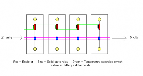
There might be a way to turn all the resister circuits on and off, I try to show how in the drawing below and explain.
The blue solid state relays(normally open) when energized by the two purple wires closes to connect the the resisters to the cell's two terminals. Because only two wires are used to turn on so many resister cell circuits the voltage starts out high at the beginning and drops to a lower voltage at the end where the relays voltage rating wouldn't have to be rated as high.
The normally open temperature controlled switches (green) which are physically attached to the resisters close above 200 fahrenheit to verify that all resisters are hot or draining electricity from the cells. So if there isn't continuity in this circuit the power to the solid state relays would be stopped because this would mean not all the cells are being discharged.
Another thing is the resisters could have much higher resistance because they wouldn't be connected all the time.
One thing no one brought up is that there is a normal drain by the system of about 15 milliamps, could that reverse charge the weakest cells after the battery is mostly discharged ?
Hi The Laird, reading your coment, you maybe misunderstood me? I would use diode and resistor as shown below.
If the diode fails the cell would discharge faster, but there would be no short circuit anyway.
Reaching 0,7V the diode would begin to cutoff the discharge.
UF: 0,3V.. 0,4V..... 0,5V... 0,6V.. 0,7V. 0,75V
IF: 0,0mA 0,02mA 0,2mA 1,5mA 10mA 30mA
(Source:http://www.elektronik-kompendium.de/sites/bau/0201113.htm)
Hi Anderson, at this ratings a simple opto-coupler would be enough, and you´re maybe right, the permanent
curent-draw of the MC could be a problem.
Greetings Mike
Hello Folks,
I have to admit , you don't seem to like my radical ideas. But, what the hell?
I have read all of the posts and Perhaps I have failed to make my 'system' clear enough.
First point.
The system described has the enormous benefit of utter simplicity, a single resistor does the job described which is to enable a means of equalisation with minimal damage / no damage. Any additional parts brings with it complications. I am trying to avoid complication.
Mikemitbike would like to see added diodes to prevent total discharge (to zero volts) of the cells. Mik has witnessed cells leakage of empty cells. Both points are interesting, Duracell describe electrolyte leakage under empty cell conditions as a 'rarity' and I suspect that it would only happen to poor quality / faulty cells left empty for long time periods.
The method which I advocate is intended to be used infrequently, perhaps once in three / six months. The cells would only be empty for a matter of days at most and would be then recharged.
If faulty cells are present then the battery is doomed anyway, if not then the battery life may well be extended significantly.
The addition of diodes, besides bringing added complications, do not always have identical characteristics. The knee of the forward bias curve can vary (between diodes) at low currents whereas the resistor tolerances are within 1% (the ones I have used). Remember we are looking for equality, total equality if at all possible.
Assuming that a cell is low capacity, when equalised by this method and then recharged using the modified charger programme, the likelyhood of further damage through overcharge is at least limited. The Vectrix charger programme forces 10 amps into the battery until 1.5 volts per cell is reached, by which time damage to low capacity cells is severe with serious overcharge of the cell with the accompanying high pressure. Using the modified charger programme, the cells are taken only to 1.4 volts per cell and then the current is reduced to 1.5 amps until the battery is 'full'. Surely, this would give better treatment to 'faulty' cells.
The continuous discharge, via the Vectrix's electronics, has been considered. It is about 6mA and would reduce or become zero at some point long before the battery is empty. The added resistors would also limit the reverse voltage which could occur (through the continuous drain by the Vectrix) because the 'reverse charge' current would be largely passed through the added resistor. Under these conditions the reverse voltage could never exceed 0.25volts, whereas without the resistor the reverse voltage is only limited by the cells reactions, if at all.
This thread is a follow on from my modified charger software and is intended to be used in conjunction with that software. I am trying to improve the utter foul up that the Vectrix corporation have made of, what should be, a simple battery charging process. Each step I take on the road to improvement is very carefully designed to fit with the parts of the process. All of this with the best of intentions on my part.
I have no desire whatever to tell anyone else how to go about improving their VX1. What I am doing, as I have said before, is telling you what I have done and how I have done it. If you wish to follow my example / system, then that is your choice and your total responsibility.
I understand the interest that some of you take in this topic and the reasons for that interest (the broken / damaged / failed Vectrix batteries and the threatened short battery life). I am happy to answer questions on my designs but could you keep the questions short, specific and to the point? it would save me considerable time when trying to give answers to the points raised.
I am already 'swimming against the tide' with the Vectrix corporation. I have sent personal messages to Xvectrix offering to work with him (for free) on improvements to the Vectrix programmes. So far, he hasn't troubled himself sufficiently to answer my messages. The only conclusion I can draw from this behaviour is that he has no intention to be helpful to us. XVectrix, without doubt has inside knowledge of the Vectrix corporation and the workings of the software. This is painfully obvious from the content of his posts. No one could know that much without being involved in the processes.
Just in case XVectrix reads this post, I am offering again to work with you (Xvectrix) for the purposes of improving the longevity of the NiMH batteries. I do not want money from Vectrix, all I require is access to the software and a little (or even a lot) of openness and honesty.
Well, I've had my say, I look forward to more questions / critisism and progress.
Keep it coming folks.
The Laird
P.S. Mikemitbike's comments/suggestions have just provided a 'Eureka' moment which I shall work on immediately. We may yet solve another issue in a very simple way.
Hi The Laird.
I don´t think it´s that dramatic. Most of the people here in the forum are maybe only very sceptical because
of their experience with Vectrix or with the importer/servicestations. And yes you sometimes give information
in a very compressed form, which is sometimes dificult to follow.
I suffered cell leaking, but only with the small cells used in cameras or walkman etc... The GP cells should
not leak as long as they are in normal position (Vent up).
I´don´t think XVectrix maybe is risking too much by helping us too much. Companies normaly have some paragraph
in their contracts if employees tell anything (technical stuff, copying software etc. ) they get sued.
[/quote]
I read the posts, and had a little "aha" when you mentioned the problems with the diode and Anderson made this
drawing with the relais. Here an other atempt or starting point: As a normal NPN transistor needs around 0,7V
on its base to work, it could be used instead a diode. The resistor (9 Ohm) cuts down the current to ~130 mA,
and protects the circuit if the transistor fails and is shorting itself. The second resistor (100 ohm) protects
the base of the transistor. [the second values where copied into the picture, the Falstad simulator don´t
show two values in that way.]
As the voltage drops below a certain value, the transistor is "shuting down itself" because the voltage is to
small for the base. By limiting the current below 40mA (~30 Ohm instead of 9) a optocoupler could be used if
it´s transistor still works with that low voltage (the diode of the coupler will need 1,2V to turn on.
If it works out, the circuit could be disabled easy if not needed!
I can´t answer, if the cell-voltage is high enough to use an optocoupler and an transistor for higher rates, as
the Falstad-applet don´t simulate optocouplers...
Greetings Mike
The CBA is a constant current discharge device. That causes the steep voltage drop at the end of the discharge curve. In the resistor circuit proposed by The Laird the voltage curve would drop much slower, because the current reduces according to Ohm's law as the cell voltage falls. Theoretically it would approach zero volts asymptotically, but never actually get to zero volt! Of course, the 6-7mA constant-on drain from the Vectrix MC will bring it to below zero volts.
The Laird: It's not that I don't like your radical ideas - far from it! I just ask questions and make comments to clarify and to better understand, and to point out potential pitfalls. The leaking cell (one out of 240) which I mentioned is a top-quality NiMH D-cell, mounted lying on it's long side. It did not leak during the prolonged deep discharge state (possibly 2 years), but only after it was put into service again for several months. I was just guessing that it might have something to do with the deep discharge. Duracell mentioning it as a rarity confirms my suspicion!
Do such battery seals need positive pressure to remain closed - i.e. will they open and then stay open if the pressure gradient falls to zero?
Another question: How do you estimate the reverse-charging voltage reduction due to a resistor across each cell? Could I reverse charge a cell and measure the voltage, and then calculate the reverse-charge-resistance of the cell (at 7mA)?
39ohm * 0.007A = 0.273V maximum reverse voltage.
How much temperature rise would be caused by the resistors? I think they will heat the middle and top layers the most, because no resistor is located beneath the bottom layer.
k1.4V/39ohm = 36mA ---> 0.036 * 0.036 * 39 * 102 = 5.15W heating for the entire battery. Because of the lack of spontaneous convective cooling and the large thermal mass of the battery, this energy will only start to be dissipated once there is a significant temperature rise above ambient.
How many degC above ambient would the battery be once in temperature-steady-state (with charged battery)?
Anderson: The temperature controlled switches would not work, the resistors will never get to 200F.
This information may be used entirely at your own risk.
There is always a way if there is no other way!
Guy's, all this discussion is very interesting, and the accumulated knowledge is really impressive!
But just to skew the debate a little, here's the thing! Apart from a handful of enthusiasts, (who from either technical interest like Matt and the Laird, or determined necessity like Mik,) have made themselves experts in battery technology, very few people are interested or can be bothered with the intricacies of battery maintaining and charging.
Will this change radically ?
Will an in-depth knowledge of battery technology become a talking point of great interest once EV's become mainstream transport?
I mean, can you see guys sitting round arguing the merits of batteries in the same way that ICE enthusiast talk about V8 v/s turbo charging? Will the same emotions run rampant?
Will the EV motorist of tomorrow, be as well educated (or just as ignorantly opinionated) as to the technical details of his EV vehicle as he is with ICE car? Will there be the same articles in motoring magazines, and shows like Top Gear?
How will the automakers label the different Marques to establish more or less powerful(desirable) models. What new parlance and jargon will be created to fill in all those Pub conversations?
Just a thought.......(I really should get back to work!)
marcopolo
Hi markopolo,
the answer to your questions is right there.
Greetings Mike
Hi there Marcopolo,
I just love reading your scripts. The breath of fresh air and common sense which you bring to the forum often blows away the cobwebs of confusion which develop within the various topics under 'discussion'.
You are, of course, right in your observations regarding the technicalities of battery management. Amongst the riding public / consumer / purchaser, who the hell cares what is 'under the hood' or 'what makes it tick'? Answer, very few people indeed.
However, from my perspective, I have a number of aims:-
One is to move the technology forward and generate improvements, hopefully to benefit everyone.
Another aim is to help those enthusiasts who want to improve their own machines by offering practical ways by which this may be achieved.
Yet another is to show 'big business' that they don't have a monopoly on good design/products indeed, as with Vectrix, they often employ very well qualified personnel who, frankly, are that stupid.conceited and/or arrogant that they couldn't re-invent the wheel even if they had a copy of the original plans.
I also write on this forum in the hope that it offers information and education to anyone wishing to learn and I never cease to be amazed by the wide readership of these articles. Why, I believe that even Vectrix personnel read this stuff. They just don't seem to possess the intelligence to make good use of it.
Anyway, thanks again for your refreshing input, Marco. Maybe you should be running the Vectrix organisation and I could provide some of the needed technical input.
Best wishes to all,
The Laird. Just telling it like it is :-)
And long may you continue to do so!!
Thank you for your kind remarks, Although I still wonder how a Hells Angel type biker will come to terms with the ethos of an EV two-wheeler?
Bat out of... er... electrons?
marcopolo
Hi guys
The_Laird, keep doing what you're doing, and don't be bothered by those who think they know better or that this has no use!
The solution is probably out there somewhere, but if everyone just keeps their ideas to themselves......
I read your posts with great interest, and I will do about anything to keep my V running for as long as possible.
X-vectrix was an employee @ vectrix, but I don't think he still is..
That may be the reason he doesn't respond?
Marco, you're right, apart from us, enthusiasts, nobody will give a damn about this stuff.
But you have to respect the fact that all of us are trying to make a better world :-)
Besides that..
aren't we all re-inventing the wheel when it comes to this?
can't we just "copy" a "normal" BMS system that measures/compares voltage at cell-level?
I wouldn't bother running 204 (thin) wires from all cells to a central point..
(please don't laugh - I'm totally ignorent :-))
And wasn't there already something like that (or part of it) inside the Vectrix? (as in: "too expensive, let's leave it out for now")
Turok
"doing nothin = doing nothing wrong" is invalid when the subject is environment
Hi The Laird,
One of my customers has a Vectrix with 630km on the odometer.
Twice now he has let his bike sit for so long, the total battery voltage has fallen below the ~85v necessary for the bike to power up.
the first time I measured the full battery voltage as 0.3V, the second time it was 11V.
None of the cells are swollen, nor have discoloured celsi dots.
based on temperature rise at end of charge, none seem to have lost any capacity either.
at such a low discharge rate, the difference in Ah remaining between 0.4v and 0.8v is trivial.
The continuous current drain is a combination of the dc-dc that powers things like the clock, and a discharge resistor across the MC capacitors (so they don't stay live).
the current drawn by the dc-dc actually increases, and is maximum when pack voltage is ~60v.
the small parrallel resistor allows self discharge of the battery to 0v.
bottom balancing is useful when you are no longer using voltage to terminate charge.
In the case of the Vectrix, that would mean using a timer to prevent a full charge.
I look forward to hearing how bottom balancing works out on a Vectrix :)
Matt
Daily Ride:
2007 Vectrix, modified with 42 x Thundersky 60Ah in July 2010. Done 194'000km
"I wouldn't bother running 204 (thin) wires from all cells to a central point.."
Actually, 102 wires+1= 103 wires... If you use the Australian BMS, only one wire...
In grupos of 3 NIMH cells, a lithium BMS may work. If you add 3 layers of LI bms to all the cells, each layer displaced only one cell, all the cells will be controlled? ... too complex...
R,
What do you mean by the Australian BMS?
Is there an existing solution??
Or were you talking about Mik's self-made "BMS"?
The Laird (or anyone)
What is your opinion on this?
can something be done if we are willing to run 103 or whatever number of wires to a BMS? a selfmade OR existing one??
T
"doing nothin = doing nothing wrong" is invalid when the subject is environment
The australian BMS for lithium:http://www.ev-power.com.au/-Thundersky-Battery-Balancing-System-.html.
It's just an idea. Every single lithium chip can work wih 3 NIMH cells. If you put 3 layers of BMS, displace the start of each layer one NIMH cell, and all the cells will be managed...
Hi R, I had a look at the site. For dischargeuse and undervoltage warnig, this BMS could be used for 3 NiMh cells per BMS module >>On discharge the cell voltage will stay relatively constant at 3.2V until near 100% depth of
discharge. Under heavy loads it may sag lower than this but will always return to 3.2V while the
cell still has some capacity. The cell modules monitor the voltage of each cell. If any cell falls
below 2.5V for more than 2 seconds the MCU will sound an alarm and can deactivate the load to
reduce danger of damage. As soon as the voltage is back in the safe range the alarm will cease.<< As the circuit reacts to voltages under 2,5V for NiMH it would be around 0,83 V for 3 balanced and maybe 2x 1,2 and 1x 0,3 for unbalanced cells. But it would not work during the charging process, as it activates the shunt around 3,65V which would cut off the charge at 1,22V per each NiMH cell. Using modules for LiPo instead of LifePO4 could work better because in this case the the shunt starts to work around 4,2 V (1,4V per NiMH). Still there is a big problem: You´re putting 3 cells together, one has a fast selfdischarge, when you charge, the 2 other cells will be overcharged again as in sum the cuttoff voltage is reached too late.
Greetings Mike
Edit:

I did a little rework on the circuit above: left how the circuit could look like right how I tried to simulate it with the applet from http://www.falstad.com/circuit/, because the absence of an optocopler. I used a diode(left) as a transistor has a forward voltage around 0,2V when fully on. the lower diode could be left if not wanted, it is a shottky with a lower forward voltage. All a bit theoretical and complicated, but with the advantage, that it could be turned on and off via the optokoppler. Maybe the values for the resistors are wrong, or could be modified for better values. If both, optocopler and transistor fail and shorten, the battery would be drained with 200 mA, but with higher values for the resistors the bottom-equilasition would take too much time
.
Hi All
This is the best, most educational thread I have seen on V in a long time.
Most impressed, keep it up!
Cheers
Paul
Hello Folks,
Nice of you all to join in.
Just one thing puzzles me and that is, Why is it that, when faced with a simple circuit / system / idea, some folks get an irrepressible urge to complicate things?
I did say, early on in this topic, that this is a simple, effective and non damaging method of equalising a group of cells / battery. You really can't get simpler than a one resistor circuit (per cell). The reliability of any system goes down as the complexity / number of components goes up.
By far the best way to determine whether this system can be improved is to build it, test it and then, if it doesn't do the job, start designing the 'improvements'.
On a personal level, I have no urge to change anything until I have a need to. I wouldn't be working on these Vectrix 'problems' other than through necessity and I intend to keep all of my improvements simple because that is where the reliability will be found.
I am prepared to answer questions but I don't intend to 'defend' my designs, or change them, without a very good reason. That very good reason would have to contain evidence of a failure of some description, by which I mean, a failure shown to have occurred in practice.
I am in process of carrying out this 'modificaton' to my own Vectrix battery right now. I have 3 blocks of eight cells under final testing at this moment. So far there is no reason to even think that this system will not work correctly, on the contrary, it is performing better than expected. Therefore, it would seem prudent to stop having 'good ideas' and instead test the idea / system under discussion. As I have already said, we need results of testing before making any changes.
In any development programme the system is Design, Build, Test thoroughly, modify design (if required) and then production. Why should we be different? I know that Vectix didn't follow that programme, but that's why we are 'fixing' the problems.
I heard the expression KISS at a seminar on Digital Electronics many years ago. One of the principle lecturers said "Don't forget the routine KISS and Keep It Simple (don't be) Stupid. Good advice if you ask me.
As always, keeping it as simple as possible,
The Laird
Staying with the single resistor per cell design, it would still be good to consider the heat rise and the reverse charging reduction caused by the resistors.
A different resistor type might be recommended for different climates or circumstances.
I also expect that different resistors will be needed for the three layers in the battery. The about 5W continuous heating power inside the battery compartment will probably leave the bottom layer at ambient temperature, while the top layer will be significantly warmer. I lack the ability to make a theoretical calculation of the overall heat rise and the differential heat gradient between layers. But I would not be surprised if the top layer ends up 5degC warmer than the bottom, because the plastic cover is so thick. That would probably cause more imbalance than it prevents, by increasing the spontaneous self-discharge rate of the warmer cells.
Can the 12 temp sensors in the battery be read individually with the scooterdiag software? If so, someone could do a measurement series to check that the sensors actually give reliable comparable results when the battery is in temperature balance. The sensors are not likely to give very exact measurements, they would need to be "calibrated" before the resistors are added. I don't think you can really calibrate them, but you can get to know them so that you know if any of them always read high or low compared to the others.
Would it be possible to use thermistors instead of resistors? Something with a steep gradient between 20degC and 50degC, so that cells experience significantly less "resistor current drain" at 35degC compared to 30degC - and practically none when the battery is already too hot? This would shut the system down when the battery is already getting too warm for good longevity. I don't know how accurate thermistors are, but when buying 1000 of them one might be able to match them closely. I also don't know how they fail and how they cope with vibration in a vehicle.
This information may be used entirely at your own risk.
There is always a way if there is no other way!
Hi Mik,
Good questions and I shall answer them as accurately as possible.
The Heating effect. The resistors will dissipate (generate/develop) heat in accordance with Heat = Voltage x Current. Heat in Watts, Voltage in Volts and Current in Amperes. Therefore each resistor will produce 0.05Watts and the whole battery will produce 102 x 0.05Watts = 5.126Watts. Each Watt/Hour equates to 3.4 BThU's (British Thermal Units - Sorry, but I loath the metric system) and the whole battery is generating heat at the rate of 5.126 x 3.4 = 15.378 BthU's per hour. I have assumed a voltage of 1.4Volts per cell for this calculation.
Without knowing the specific heat of the battery I will assume that it is around 0.25 and with a battery weight (all right Mass) of 180Lbs it will require 45 BthU's to raise the temperature 1.0 degrees Fahrenheit. So theory says that the battery will warm up at the rate of 0.3 degrees F per hour or 8 degrees F per day. In practice it will also be losing heat at a rate dependent on the ambient temperature and the battery temperature. At some point equilibrium will occur i.e. the gain of heat will equal the loss of heat. Until tests are complete I do not know at what temperature this will happen But, I suspect that it will coincide with the battery being between 2 and 6 degrees F above ambient.
Any raise of temperature will be offset by the effects of the plenum fans whilst riding and charging. Compared with the potential heat lost/generated by the cells internal losses these heating effects are quite large. Duracell's figures give a potential for power loss of about 10% capacity in 30 days at 32 degrees F. this equates to 0.6Watts continuous, at 68 F the figure rises to 1.2 Watts continuous whilst at 113 Degrees F (45 degrees C) the heating effect is equal to 3.6 to 4.8Watts continuous.
However, consider the heating of the battery when the bike is in use. Riding at an average speed of say 30Mph the battery charge will be 'used' in one hour. This requires an average current consumption of about 20 to 25 amperes with peak currents up to 150 to 200 amperes. The internal losses (heating effects) of the cells increases with increased current drain and is equal to I x I x R where R is the cells internal resistance and the two I's are the current in amperes. At 20 amps the power generated within each cell is 0.48Watts or 49 watts for the whole battery. At 100Amperes (much less than maximum) the loss per cell is 12.0Watts or 1.2kWatts for the whole battery. In that one ride the battery will be subjected to the heating effect of something in excess of 50Watt hours. In a high speed ride say 60Mph continuous for 25minutes (you won't get more than that, I suspect) The battery will be subject to a heating effect of 3Watts/cell and 306Watts (for 25minutes = 150WattHours) for the whole battery. The battery must be able to dissipate this heat, if it did not then a condition known as thermal runaway would occur and the battery would burn itself out literally catching fire in the process.
The resistor values have been chosen to give an acceptable equalisation time. Higher resistor values lengthen the equalisation time and allow potentially higher reverse voltage on the cells (if this were to occur).
All resistors have to be equal in value or equalisation will not occur. The difference in the cell 'layer' temperatures will be minimal, not more than a degree or two and will have little effect on cell internal losses.
Thermistors are not a practical option at this stage as their tolerances are far too wide.
The Diagnostic software does show the individual module temperatures and the readings are accurate when compared with each other. Following a three or four day break from use, I have recorded temperatures of all cells modules being equal throughout the battery with the occasional 'twitching' of one or two temperature up or down by 0.1 degrees. I shall be monitoring the temperatures very closely when the modified battery is assembled and fitted.
All of my resistor assemblies are built and ready to fit, I am awaiting delivery of an 'engine crane' to lift the batteries from the bike. I expect to have the whole job completed within a week of the crane's arrival and will report results as they become available.
Still keeping it simple and hanging on in there,
The Laird:-)
If you have the time, re-tighten the inter-module-connectors after a few hours rest, preferably with a torque wrench. Or decide if you want to use thread-lock.
Otherwise you might produce a pre-battery-recall-equivalent battery, with loosening connections some time down the track.
It will be most interesting to hear about the test results when it is all installed.
Could you possibly run a little test on the thermistors before taking it apart, once the battery lid is off? Like putting a finger on one sensor for a little while to warm it up and see if it really is so closely matched to the other 11 sensors. It may all be due to my soldering extra cables to the temp sensors.....I always get 1,2 or 3 degC differences between sensors when I measure it through the Manual-BMS (using a $20,- electronic thermometer to "convert" the raw data from the thermistors). Hearing from you that they are within a tenth of a degree of each other is encouraging, that would allow very accurate testing of the differential heating effect of the per-cell-resistors (if any).
This information may be used entirely at your own risk.
There is always a way if there is no other way!
Hello Folks,
Finally, I'm back with a working Vectrix.
My engine crane arrived, batteries have been out, modified (resistors added), faulty cells replaced and are now back in the bike and in service and looking better than ever.
The resistors have added a permanent 3 degrees (F) to the battery temperature (when measured against ambient temperature) which is more or less as expected.
Measured power input to the batteries is (empty to full) is:-
Mains input to charger = 4500Watts
Charger output (at 85% efficiency) = 3825Watts
Battery Input (Conversion efficiency at 95%) = 3634Watts
Less Fan Power (134Watt Hours Total) =3500Watts
At Charge Voltage (averaged) of 142 Volts = 24.65 AmpereHours.
The above figures result from running down to the 'red light' (Battery = 126 Volts) and charging to a maximum of 146 Volts ( I am using the modified charger software).
Battery temperature at rest is consistently at 3 degrees F above ambient temperature. In use, a battery temperature rise of a further 3 degrees maximum has been observed (remember that the plenum fans are always 'on').
Range was 36 miles, speed averaged about 30Mph, the journey covered 1800 feet of hill climb and 1800 feet of descent with speed bursts of 45 - 50 miles per hour.
All in all, I am well pleased with the final result, although the bike has only been through nine charge /discharge cycles since the rebuild.
A second Vectrix, running the same modified software but without the battery (resistor) mods, is showing an improvement in range also, which so far, confirms the theory of "Less battery heating = Less battery (internal) leakage and Less battery damage".
All information concerning these modifications is already contained within this forum topic. I will answer any questions as they come up and I hope to post performance updates periodically.
Still keeping it simple and hanging on in there,
The Laird:-)
Fabulous news!
I would assume that the 1.8degC temperature rise would be similar at higher ambient temperatures, like when the battery would be at 35degC, it will be 36.8degC instead. That's an acceptable temperature rise and can be more than compensated for by either running the ABCool in the cool morning hours, or, if using your modified software, by the constant-on state of the cooling system while driving.
Lower charge current seems to result in a better "filling" of the battery, resulting in better range and better power, at least after longer periods of inactivity. I am not sure at what point the losses during charging will be higher due to the slow charging, but the 864W version is definitively not causing such an effect. At less than 3A there might be issues with losses during charging, or particularly at 0.3A, but the rejuvenating effect after a long break in usage is great due to such very slow charging.
This information may be used entirely at your own risk.
There is always a way if there is no other way!
A question I forgot: Do the temp sensor readings show any discernible degree of differential heating between the three layers?
This information may be used entirely at your own risk.
There is always a way if there is no other way!
Corrected :-)
The science and logic in the Diode idea is better than the Resistors.
The Resistor idea has flaws
1) resistance increases with heat, so the wires on the higher voltage cells will get warmer, thus increase resistance - partially negating the theory that they burn off more
2) Energy is wasted
3) The resistors wont be EXACTLY equal, this will be an unbalancing force.
An analogy -
say Im unhappy that some weeks I don't earn as much money as others..... well if I throw half my cash away each week then there wont be so much difference to complain about Haha!
Hi Folks,
Thank you Andy. In my hurry to post and due to concentrating to get the maths right I omitted the 'Hours' in what should have read WattHours. Stupid boy! Thanks again Andy
Mik, There is no discernible difference in the battery temperatures between the three layers of cells.
Colin9876, There are times when theory (science and logic) and practice differ dramatically (usually due to theoretical errors but sometimes due to practical considerations), This is one of those times.
Your analogy is a perfect example of the difference between logic/theory and practicality. Throwing away half your pay each week will definitely result in you having only half of the original difference, but it does produce the unwanted side-effect of displaying serious stupidity and lack of expertise and understanding of practical matters.
The tolerance of the resistors is 1%. This is, of course, plus or minus 1%. On a total discharge of 30 Ah, the maximum possible difference in cell discharge is 1/50th of 30Ah. I doubt that the cells themselves are better than 1% in capacity variation when manufactured. The added complexity of diodes etc has no practical advantage but does have considerable disadvantages.
I have designed, prototyped, tested, finally carried out my design modifications and have now begun major testing of the whole assembly. So far, it seems to be performing well. I look forward to hearing how well your own modification performs.
Please remember, folks, I am not suggesting that anyone else follows my lead or ideas or modifications. I am posting them only for your information and entertainment.
Just looking back over the past posts. Bottom balancing (equalisation by total discharge) is not new. Since developing this idea (I honestly thought that it was NEW!) I am reliably informed that submarines have used this technique for years because they didn't need a boat full of hydrogen and oxygen using the equalising by overcharge method. Makes lots of sense when you think about it.
Still keeping it simple and hanging on in there,
The Laird:-)
Pages