Step Up, Boost DC-DC Converter for Car
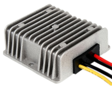
Days ago I received an enquiry asking for a step up dc-dc converter, converting 12v to 24v with 25A output. That is up to 600 Watts. The client was going to use it for radio in Ford cars.
There are plenty company making step down (buck) dc-dc converters, usually reduce 24v/48v to 12v, with maximum 500W output. But a step up (boost) one is not that easy to find, needless to say a 600W one.
In fact, current-logic.com has step up dc-dc converters of 500W. But to increase the output by 100W is not that easy as it may seem. And the most difficult part will be maintian a low temperature.
Normal DC-DC converters for cars operates at -10C to 55C, which is quite sufficient for daily use. But this client require the range to -40C to 70C! This will triple the cost of the product, and price can be as high as 500USD. They are mainly used in industry fields or maybe military vehicles.
So we have to develop a new device to upgrade the normal dc-dc boost converter for cars to meet the needs, but not apply industry grade design. So we can reduce the cost of final product and make it suitable for a car use.
When the product prototype is done, I'll post it.
- current-logic's blog
- Log in or register to post comments

Who's online
There are currently 0 users online.
Who's new
- eric01
- Norberto
- sarim
- Edd
- OlaOst
Support V is for Voltage

Comments
Re: Step Up, Boost DC-DC Converter for Car
Hi,
could you explain what it would take to build a really big step-up DC/DC converter?
How much would it cost?
What would be the theoretical limits?
To give an extreme example:
7.2V to 125V step-up converter with 23kW peak, 10kW constant power?
Can this be done, theoretically at least?
This information may be used entirely at your own risk.
There is always a way if there is no other way!
Re: Step Up, Boost DC-DC Converter for Car
7.2 volts can be stepped up to 125 volts, or any other voltage, and 23 KW peak/10 KW average is POSSIBLE, but definitely not likely to be EFFICIENT or PRACTICAL! Why? The input current, at 7.2 volts, would peak over 3,000 Amperes! Such high amperage would requre very heavy and expensive copper or silver buss bar connections, and attempting to keep switching losses low in the D.C./D.C. converter would be a challenge. (For your proposed power level, I would advocate starting with at least 28 volts D.C.- current would then be about 1,000 Amperes, but circuit losses could be better controlled, and the circuit would be much more efficient.--Bob Curry
Robert M. Curry
Re: Step Up, Boost DC-DC Converter for Car
Well how possible is a 3.3v to 24v step up converter?
I got some lovely heavy duty lifepo4 batts from Yesa, and because theres always the issue of series charging etc I wondered if I could use just 40amphr batt on my scooter and ramp it up. (they operate fine at 10C so they can cope!)
I guess at 100% efficiency 3.3v 40ahr would be similar to a 24v 5ahr batt but I would have only one cell to charge and hence no balancing?
Theres real gains in having only once cell. Ive seen theres also 3.3v 120ahr cells which would be equiv 24v 15ahr if bumped up!
Re: Step Up, Boost DC-DC Converter for Car
Well, depending on how great the losses are, that is not necessarily impractical. I have a whole heap of NHW10 Prius sticks, they are 7.2V nominal and can easily produce over 100A peak current. To have them all in parallel would simply involve two thick plates to screw them onto. And the short connection to the converter.
I need 51 of them in a 3p17s configuration to make the 125V nominal for the Vectrx motor controller, which draws up to 220A (voltage drops to about 108V during this).
If I could put 51 of the NHW10 sticks in parallel, then each would only contribute 3000/51=58.8A during peak acceleration! A piece of cake for them!
They could then be charged with a CV charger to 8.4V or 8.5V, so there would be no risk of negative delta-V etc, they would be perfectly balanced all the time, no need for a BMS! That would be NiMH battery technology at its best!
This pack would also be substantially smaller than the original pack and would leave quite a bit of space for a converter, including a 50W dedicated cooling impeller for the converter....
What level of efficiency could such a converter achieve, just roughly?
How large and how heavy would it be, and how much would it cost to make one?
Sorry if I take up too much of you time here, but it will also keep your post on top of the heap and give you opportunity to show your expertise and knowledge in your specialized field!
This information may be used entirely at your own risk.
There is always a way if there is no other way!
Re: Step Up, Boost DC-DC Converter for Car
Wow, I didn't expect so many comments!
I'm not an expert, my job is maketing. But I can give you some info I know.
Convert 7.5V to 125V, 10kW is possible. In fact some electric automotive manufacturers use 12V->280V converters to run their vehicles. The cost should be more than $1500. Effeciency can be 90% or more (no less than 85% for a serious product).
The weight, ..10kg maybe, I'm not sure. An 10kW power supply of 7.5V is out of my imagine, lol
Cheers
DC-DC Power converters
Re: Step Up, Boost DC-DC Converter for Car
Mik,
Having spotted this thread I thought that I might add my two pennyworth.
Your basic idea of converting from low to high voltage to avoid the battery monitoring and charge correcting on the Vectrix system sounds good. BUT, it does bring in a different set of problems such as the high cost of the converter, the high currents being converted and the enormous cabling required to carry the converter input current plus the volt drop on that enormous cable.
Electrical practice for power transmission (the movement of current) is to aim for high voltage, low current and small cross section cabling.
I too have considered the possibilities and have concluded that the best path would be to reduce the battery voltage to an inherently safer level of around 36 to 72 volts. This reduces the battery management system requirements, reduces the cost of the converter, reduces the converter input current levels, reduces the volt drops and cable sizes.
Some of the figures you are using seem to be erroneous. The Vectrix has a 125 amp fuse at the motor control panel. This indicates that at no time does/can the Vectrix use more than 125 amps or the fuse would not last long. So the converter would only need to provide a maximum output of around 120 Amps in order to satisfy the motor controller.
There will be a practical point at which the Voltage conversion ratio will give a useful balance between the costs, system losses, the gains of minimising the battery management system complexity and the problems of balancing the individual cell charges.
Unfortunately there is no ideal practical solution. Best plan is to go for the most practical compromise.
Re: Step Up, Boost DC-DC Converter for Car
But only one "cable" is needed in the setup I have in mind, maybe 60cm long and straight. A fat copper bar should do. The other pole of the transformer would be bolted straight to the Bus-plate of the battery pack.
.
If a battery pack was designed for such a transformer, then practically no fat cabling would be needed! The batteries would get individually screwed into heavy duty metal frame, which at the same time provides stability, access for cooling air flow and electrical conductivity. It would of course need an isolating layer between positive and negative pole. The transformer would get bolted or welded straight to the frame, or manufactured in one piece in the first place!
As for high cost: I was told that transformers last extremely long times (meaning decades or longer) if they are not under-sized. If they are big enough to stay cool, then it's a one-off expense for a lifetime worth of EV's!
If the transformer costs $2000.- then that would still be very efficient due to the extended battery life and reduced battery costs and absent BMS costs.
The transformer would also be an excellent charger! It could provide recharging capabilities like unsupervised CV charging, reaching FULL SOC asymptotically but starting with hundreds of amps. That would be fast, gentle and efficient! The Vectrix charger alone costs several thousand dollars.
I fully agree with the safety aspect, and still waiting for JDH2550_1's engineer to get back to us on that one! http://visforvoltage.org/book/ev-collaborative-hand-books/6719#comment-38402
No, the numbers are correct. That might one reason why the fuses do indeed not last long! See http://visforvoltage.org/book/ev-collaborative-hand-books/6916#comment-40025 for logged CAN data "proving" it. The peak current of 218A is also consistent with the advertised specifications of the motors peak power, my measurements of the voltage drop under peak load, and the good acceleration at 75km/h. (218A x 108V = 23.5kW)
Sure. I'm just trying to determine what the big landmarks are - i.e. between which extremes will the practical compromise have to lie somewhere?
This information may be used entirely at your own risk.
There is always a way if there is no other way!
Re: Step Up, Boost DC-DC Converter for Car
Bump-di-dump-di-dump-di-bump.......
This information may be used entirely at your own risk.
There is always a way if there is no other way!
Re: Step Up, Boost DC-DC Converter for Car
Hi,
Do you still have a whole heap of these sticks? Would you be willing to part with a few? I need sticks which still have >4Ahr capacity, and self-discharge low-enough so that still >7.8V when left 24hrs at 25degC.
Can you help?
Thanks
Ian