MB-1-E Part One: Electric Conversion - 1985 Bridgestone Mountain Bike

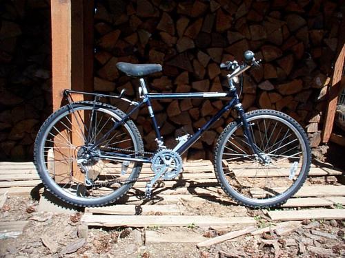
1985 Bridgestone MB-1 BEFORE Conversion:
(Note: I will be adding some diagrams and photos as the project progresses and I have time to add them)
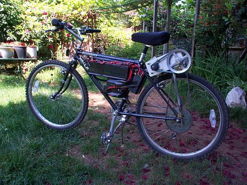
Not fully refined but a working proto-type
How It All Began
As Spring hits the Pacific Northwest, I find myself wanting to get out and enjoy the great outdoors.
I've had a Mountain Bike for many years, but haven't been riding it in the last 5+ years.
Well, my wife asked me to work on her bike a few weeks ago and to be blunt, it's a POS ... so I went out and bought her a new one. Boy, have bikes changed since I got mine back in 1985. Hers is a 21 speed, front suspension, very reasonable cost ...
Since my bike was a quality bike to begin with, I took it all apart, replaced the bearings, cleaned and adjusted everything and polished the few chromed bolts that were starting to rust. In the process I found out that my old bike is now quite sought after, since Bridgestone went out of business in the early 90's.
I decided that I wanted to convert it to an Electric Bike, but due to the fact that it's probably worth more now than it was when I bought it (approx. $520 back in 1985), I didn't want to compromise it doing a conversion.
I got on the web and found many resources available ...
... one of which was Eric Peltzer's Electric Bike site.
I liked the design and he has done a great job of documenting his build, so I wanted to do something similar. It's not surprising that Eric did such a fine job, he is also a sculptor, creating some pretty cool looking works of metal art.
As any of you, who have already converted a bike, will testify, every bike, every motor etc. is slightly different and requires quite a bit of customizing.
"One Size" does not necessarily fit all.
At any rate, when I read about and viewed Eric's bike, I was hooked. I envisioned how fun it would be to ride the back roads around here. There are lots of abandoned logging roads here that have been closed off due to lack of funding to maintain them. Some are still open and I do take the 4WD Toyota on many but there are tons more that have what we call "Tank Traps" or bulldozed trenches and berms to keep the 4WDs and cars out. It's either State or mostly Federal land, so it's open to the public, just not accessible by car or truck.
These roads are sometimes rather steep, dirt or gravel, usually overgrown and the requirements to traverse them would be somewhat different than your average electric conversion kit.
I don't like the noise, destruction and pollution of ATV's or Dirt Bikes, so an Electric Bike that I can charge using my 50W wind generator and 37W solar panels at home seems like the way to go.
Perceived Requirements for this conversion:
...Use existing Mountain Bike for the conversion
...Be Durable
...Ability to climb dirt/ gravel inclines
...Be light enough to lift into the truck and over obstacles
...Have a fairly good range
...Be easy to work on and maintain
...Keep the conversion cost down as much as possible. ($500-$700)
The Motor:
Eric's bike has a nice 1hp Scott. Scott motors this size seem to cost around $250+ no matter where you get them. I was lucky and found a new 3/4hp Scott for $50 on eBay ($68 w/ shipping).
It's a 24V 560W 3000 RPM DC motor rated at 30A
The motor has a 5/8" keyed shaft on both ends which makes it pretty versatile for various setups.
The Controller:
Eric Peltzer's latest version uses a 180A Controller.
Controllers are expensive! A 180A was over my budget by a considerable amount.
I'm not sure what Amperage the Scott 1hp pulls at 24V, but it's bound to be more than the 30A of my 3/4hp Scott. With this in mind, and the fact that I will adjust the gear ratio as necessary to keep the motor from exceeding the controller's maximum amp rating, I decided to go with a 100A Controller. (I hope I won't regret it, but the Navitas 100-36 does have thermal protection and is rated at 30A continuous at 24V or 20A continuous at 36V with 100A max. This was within my budget. I'll be keeping an eye on the temperature of the controller and may decide to incorporate a heat sink into my design.
The Throttle:
The Navitas 100-36 will accommodate either a 0-5k type throttle or Hall Effect type. I decided on a 0-5k twist grip for my build. I considered a thumb lever but decided that there wasn't much room with my Shimano gear levers already taking up the position that would work the best for good throttle control.
The Batteries:
This is another area where my budget was taxed. This, however, is my gas tank so I tried to put as much capacity as possible into the design without getting too bulky, too heavy or too far over budget.
I wanted the center of gravity to be as low as possible, while keeping good clearance under the bike for traversing the terrain.
I used AutoCAD to figure my clearances and went back and forth between my 3D drawings and battery retailer's websites to get the dimensions of batteries that would best fit the area I had to work with.
I wanted all of the batteries to be the same capacity and my mountain bike frame is an 18" model (rather small), so it took a while to come up with the best size.
I was able to fit eight - 9Ah 12V AGM SLA Batteries (UB1290) in and below my frame opening without pedal interference. (At least in CAD that is ...)
edit - (Note: Some changes were made to the following as noted later in the project)
I'll be making a battery enclosure using acrylic sheet .093" thick. The plan is to make the case fit within the frame opening (under the horizontal bar).
I'll use existing socket head cap screws (used for attaching a water bottle and pump etc) to attach the enclosure. Next I'll place 6 of the batteries into the enclosure at various angles to fit. Once in place, I'll use a spacer of some sort to make room for the terminals and connections and wrap each battery in plastic wrap. Next, I'll use expanding foam to take up the spaces between the batteries. I'll remove the batteries, plastic wrap etc then trim off the excess foam with a hand saw.
I'll make a cover for the enclosure out of the acrylic sheet and secure with some thumb screws. I'll make a smaller frame or enclosure for the two batteries below the frame.
The controller will be out in the open so it keeps cooler. It will be in a protected area (it's only 2"x3"x1") so fairly easy to place.
The Jackshaft:
The 3/4hp 560W Scott Motor turns 3000 RPM so obviously needs reduction. I'm going to start out with a 9:1 reduction but may go with as much as 11:1 if needed to reduce the load on the controller.
As Eric's site so helpfully pointed out, in order to keep a chain from being too noisy, they are best kept down to 1000 RPM or less. (That's not a direct quote, but, generally, what I understood about chain speed).
I will, therefor, be using a V-belt to reduce the motor rpm to 1000 RPM at the jackshaft.
I'm having the jackshaft made by "Tuff Industries", a very helpful outfit that I found on E-bay that specializes in jackshafts and go-kart assembly fabrication. The jackshaft assembly will consist of a flat vertical plate with a 5/8" dia keyed shaft that runs horizontal and parallel to the motor shaft.
It has a welded on hub that houses the bearings and will have a 6" dia aluminum sheave on one side of the plate and a freewheeling 22 tooth #35 chain sprocket on the other side of the plate. The plade bolts directly to the Scott motor and should be easily adjustable for belt tension and very stable.
I will fabricate an adjustable support shaft that is in line with the #35 chain and mounts to an existing boss on the back of the bike frame. This should provide easy adjustment for chain tension.
The Rear Sprocket:
I wanted this to be a "Pedal Assist" for several reasons. One is the law on motorized bicycles here in Washington requires it to have pedals to be considered a non-licensed vehicle. Two, I will be on back roads and if something breaks or my batteries run out, I want a way to get back home or to my truck.
The #35 driven sprocket will, therefor, need to be on the left hand side of the bike.
Since I don't want to make any permenant changes to the bike, I'll be making a sprocket mount that uses a split ring backing plate (sort of like the Currie attachment).
I ordered a cheap 60 Tooth go-kart steel sprocket that has a bore of 1-3/8" and a bolt circle of 3-1/4".
By my measurements this should slip right over the outside of the rear hub w/ slight modification.
I'll make the split backing ring with a 3" I.D. and 4-1/4" O.D. so it surrounds the hub (inside of spokes) and sandwiches the spokes between this and the 60T sprocket. I'll make some neoprene gaskets for each side of the spokes and use some spacers at the bolts to keep from damaging the spokes.
The Motor/ Jackshaft Assembly Mount:
From my best sources, I've learned that the closer I place the motor and jackshaft to the seatpost, the more stable and better off I'll be. (Thanks to both Chuck and to Robert, my brother).
The bike frame has two factory brazed, threaded bosses that are in-line with each other. I think that this will be the bast place to attach the motor mount.
I want the mount to hinge at this point so that I can loosen the attachment bolts, tighten the chain tensioning rod then re-tighten the motor mount bolts.
So the motor and jackshaft will be one unit and hinged at mount.
Wiring:
Initially I'll make this a 24V system.
I'll place the batteries in Series/ Parallel to provide 36Ah at 24V.
Charging will be a bit of a challange since I only have a good 15 Amp 12V charger right now. It's an Iota that has the QD4 three stage charging controller and should work well with AGM batteries.
I think there is a way to wire the batteries so that they are what I've heard called "Buddy" Series/ Parallel. From what I know this is a system used by Alternative Energy folks and is supposed to keep a better balanceed battery bank when using Series/ Parallel. I'll have to do more research to figure this one out.
The point I'm making here is that in using this system, if it's wired the way I think it is, I will at least be able to charge 4 batteries at a time (of the 8 total) without disconnecting any leads. (I'll post a diagram of this later, to see if any of you are familiar with doing it this way).
I'm not worried about lights yet, I think I'll just use separate NiMh cells for lights.
I will need a good battery disconnect and a 4 wire key to turn the controller and possibly later lights on and off.
As noted, I'll be updating my blog as I progress.
Any and all comments are welcome. There are a lot of good minds here that will likely know or see something I haven't taken into account. I'm open for suggestions at any stage of this project. I either have all parts or they have been ordered and will be here shortly.
Finding the time to put it together and further engineer it is another story.
Thanks for visiting my blog.
Dave
- MB-1-E's blog
- Log in or register to post comments

Who's online
There are currently 0 users online.
Who's new
- eric01
- Norberto
- sarim
- Edd
- OlaOst
Support V is for Voltage

Comments
Re: Electric Conversion - 1985 Bridgestone Mountain Bike
This will be fun to watch.
If you should need to add a heat sink to your controller I snagged several pieces of black anodized finned heat sink material off the surplus pile at work about 4 x 4 inches with around 1 inch fins. PM me if you want me to send a hunk or two of it to you.
You could run two 12v lights in series or get some 24v bulbs if you want to run your lighting from the motor batteries.
Good luck and keep up with the excellent posts.
Re: Electric Conversion - 1985 Bridgestone Mountain Bike
Dave,
Found that sprocket mount
http://www.spookytoothcycles.com/component/page,shop.product_details/flypage,shop.flypage/product_id,162/category_id,72/manufact...
For $24.95, I was'nt able to find what size chain the sprocket accepts though.
chuck
[b]AGM BATTERIES[/b]