These scooters generally use a hall throttle but the controller expects a 0-5V signal, and doesn't bother if it comes from a hall or from a potmeter.
The controller also fails to stsrt-up oroperly if the initial voltage sensed on the throttle input is too high. So I'd check the actual voltage from the throttle.
With gnd and 5v+ hook up to my throttle, I get these readings:
5v = 5.03v that's good
signal line with closed throttle 0.9v, up to 4.3v WOT. so far so good.
Now, when I connect the signal line to the controller, it is now 1.9v. Because of this, I get a fault (and if I didn't the bike would move with no throttle movement).
What's the easiest way to fix this? A diode on the signal line? It seems that my throttle is not the problem.
It looks like the controller is outputting some current on the throttle input.
I'd try inserting a suitable (i.e. value to be determined experimentally) resistor between throttle out and gnd.
Let's say start with 1k and then report the value.
With this controller you don't want too low initial voltage otherwise you are getting a unwanted dead-band.
I had the opposite problem on my Efun-D, the "0-turn" voltage and the actual "go" voltage were too far away and so I used Fetcher's mod (a resistor in series with the throttle gnd return) to lower this difference.
I just put my precharge resistor between the gnd and throttle input and it works well now aside from the normal dead spots at the beginning and end.
I think it's a 1k 1/2watt resistor. With it connected, the throttle input is resting at .79v
Thanks for the help, I'm really happy to get this working.
Spearo - you say you upgraded the controller to 72v? From what I read earlier in this thread, we need to change out the R29 resistor to a 165k, correct? Is there just one of these, or two (two boards)?
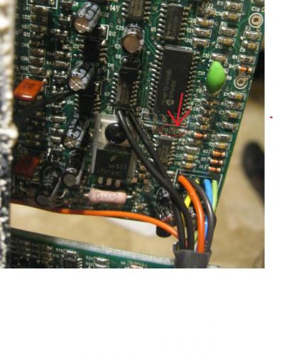
Is this the correct one circled in the pic below?
These scooters generally use a hall throttle but the controller expects a 0-5V signal, and doesn't bother if it comes from a hall or from a potmeter.
The controller also fails to stsrt-up oroperly if the initial voltage sensed on the throttle input is too high. So I'd check the actual voltage from the throttle.
I have this about diagnosis leds
I took a volt meter to the throttle wires.
With gnd and 5v+ hook up to my throttle, I get these readings:
5v = 5.03v that's good
signal line with closed throttle 0.9v, up to 4.3v WOT. so far so good.
Now, when I connect the signal line to the controller, it is now 1.9v. Because of this, I get a fault (and if I didn't the bike would move with no throttle movement).
What's the easiest way to fix this? A diode on the signal line? It seems that my throttle is not the problem.
It looks like the controller is outputting some current on the throttle input.
I'd try inserting a suitable (i.e. value to be determined experimentally) resistor between throttle out and gnd.
Let's say start with 1k and then report the value.
With this controller you don't want too low initial voltage otherwise you are getting a unwanted dead-band.
I had the opposite problem on my Efun-D, the "0-turn" voltage and the actual "go" voltage were too far away and so I used Fetcher's mod (a resistor in series with the throttle gnd return) to lower this difference.
I just put my precharge resistor between the gnd and throttle input and it works well now aside from the normal dead spots at the beginning and end.
I think it's a 1k 1/2watt resistor. With it connected, the throttle input is resting at .79v
Thanks for the help, I'm really happy to get this working.
Spearo - you say you upgraded the controller to 72v? From what I read earlier in this thread, we need to change out the R29 resistor to a 165k, correct? Is there just one of these, or two (two boards)?

Is this the correct one circled in the pic below?
Pages