I Set up series/parallel switching on my 900watt scooter with a 4 pole double throw (4PDT) switch from Mcmaster-Carr.
Here's some detail
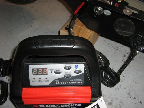
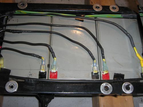
There was a lot of wiring to do, and I attached a diagram of which terminals of the switch go to which batteries. I used 10 AWG wire for most of the wiring, and some 12 AWG for the wire soldered to the switch because I had some special with high-temperature insulation (so it didn't melt when soldering). Each positive of the batteries went straight to a 35 amp fuse before going to the switch or anything else. The main positive and negative to power the scooter are just taped off the + of B1 (after the fuse), and the - of B3. Finally, the charger (a B&D Vector 10/6/2 amp 12v) just goes to the positive and negative of B1. This is so that if the charger is plugged in and the switch is switched to wire the batteries in series, then the charger won't see more than 12v and there will be no risk of frying it. This way, I have to make sure the switch is down or only one battery will be charged. I thought of taping off the main positive and negative of the pack to the charger port, which would also allow plugging in a 36v range extender pack through that port, but again, this would risk frying the charger if I plug it in while the batteries are in series.
The switch (item # 8001K38 from McMaster-carr) is rated to handle 25 amps at 125 VAC, and 20 amps at 30 VDC. I think this is how much current it can switch live, so it can handle more current if not switching during current flow. I would bet it wouldn't heat up too much when running 35-40 amps continuous. I'm using it at 20 amps continuous.
This takes considerable time to do. Soldering 10 AWG automotive wire with a 60 watt soldering iron got this wire very hot. I had to solder 3 wires together at a few joints which required getting them very hot and melting some of the insulation. If I did this again, I would use 12 AWG wire to make it easier. 12 AWG would probably be ok up to 30 amps or so.
My thoughts
I think this compares favorably to other options on a small scooter to balance the batteries. I could get 3 12v chargers, but those would still be a pain to wire up, and cost $60 ($20 ea for cheap ones from batteryspace). I could get 2 power cheq or battEQ units (the 2-battery model overlapped), and those would cost $130-140, and in addition I'm still stuck with my crappy slow inefficient 36v stock charger unless I get a better one for more $. Not to mention, it would take time to wire those up as well.
As it is now, I'm using a quality Vector charger for $45, the switch was $13.42, and the wiring and charger anderson connector was probably another $5-10. I can charger in about 2 hours from completely dead, and I have a low-speed mode (by switching the batteries in parallel) which is good if the batteries run flat on me to get a little further while reducing the risk of damage to them. And, this switch has a middle off position, so I can switch it off which totally isolates the batteries and eliminates the risk of any leakage current to the controller.
Diagram
Battery terminals to switch, facing rear of switch
Pictures
Old Setup:
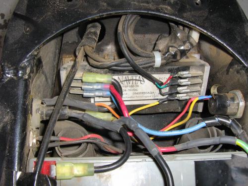
New Setup:
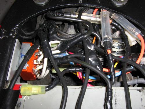
Note how all battery terminals need a wire leading back to the switch:
The switch, charger connector, and charger. Down is parallel to charge, up is series to ride, and middle is off: