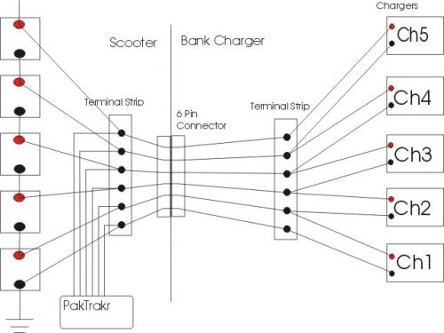
By looking through some Endless Shpere postings, I realized that using 2N wires (N= number of batteries) is N-1 wires more than needed. You really only need 6 wires for 5 batteries (N+1). I show a PakTrakr connected too, which is of course optional. I thought this might be helpful for anyone that wants to do bank charging on a scooter. This is a five battery example. They are doing this type of setup with up to 16 a123 batteries over on ES. If I can find a good 6 wire connector, I may change mine to use just the required wires.


that looks great and seems electrically right. I was about to install the bank charging wiring from my original Zapino into my new Zapino. I need to check this out. Will make the system much easier to install and maybe we can find a better connector then the ones I have now. I already have it wired for 12awg so it will handle the 4 amp charging voltage OK. As it is now, there isn't any isolation between the chargers so your diagram looks pretty much the same.
Robert Dudley
E-Scoot Tech
Do you want fries with that?
ZEV 7100 Alpine
Fort Collins, CO
I proved nothing like that! Actually, I proved that the middle wire works fine to account for imbalance. Think of it this way, I disconnected one battery which represents a charger, and the corresponding load saw full voltage from it's battery. The same worked for the other load. This is because the "middle wire" was transferring the power in the first two pictures.
It is as if each load was independently connected when I had the middle wire connected. What I should of posted was a 6th picture that showed that with the "middle wire" disconnected, I could not power each load with it's corresponding battery, unless both were connected. This would indeed be a series circuit WITHOUT the middle wire connected.
I feel dumbfounded. I try and disprove one of usatracy's claims, and it is used against me by usatracy to seemingly support another false claim. Lets try and focus here. Just on one thing at a time.
I'll do that test, and I'll demonstrate that astar's wiring scheme works fine to balance batteries during charging. I have enough batteries around, here's the setup I'll use:
(2) 12 ah batteries fully charged (which can be shown to be fully charged by picture of power supply at 2.45 vpc drawing less than .01C). Same batteries as in my last test.
Put one battery on 50 amp load for 1 min. Put the other battery on 50 amp load for 3 minutes.
Use astar's wiring scheme and show that both batteries are:
charged in the same manner as if they were charged in completely independent circuits.
[url=/forum-topic/motorcycles-and-large-scooters/587-my-kz750-electric-motorcycle-project]KZ750 Motorcycle Conversion[/url]
[url=/forum-topic/motorcycles-and-large-scooters/588-fixing-my-chinese-scooter]900 watt scooter[/url]
Pic from http://www.electri
Thank you for the response. I hope this isn't too much of a thread drift, but because of the title and the number of responses, I think this will get quite a few reads.
Its well-established that lead-acid batteries should be charged early and often. Topping off at work will greatly extend battery life, a major cost benefit on top of having longer range per a given commute.
Having 5 chargers for 5 batteries is awkward to either carry, or expensive to have at both work and another set at home. I am relieved to hear a simple string-charge to 90% at work, and full bank charge at home in the evening is viable.
"Gang-plugs" of any desired size are easily available. I would like to have two charging wires from each battery connected to a 10-pin gang socket. The work plug would have two charging wires (pos/neg) connected to the appropriate pins, and the other pins would connect to each other to form a series string.
At home, the same plug (which could only connect to the socket one way) would have the 5 chargers attach to the 5 individual batteries.
Still learning..., will this work, or am I missing some part?
Spin,
After reading your last post I was very impressed. You seem to grasp the logic of battery care and feeding very well and your idea for using a gang connector is right on. There is a product on the market called Sermos or Anderson Power Poles. Some people use one name some the other but they are one in the same. The reason I bring this up is they are designed with an interconnect on each single connector. You can arrange them in almost endless combinations with as many wire connections as needed. Here is a picture of 2 connectors one red one black.
They can be connected together to form a 2 wire connection which is most common. They also come in a variety of colors and the interconnecting of the connectors allows you to rotate the connectors orientation so it's mate can only connect in one direction, which is something you said you wanted.
Grandpa Chas S.
If I understand what you are saying, this is dangerous and would short out your 2, 3 & 4 batteries. If your charger connector has 10 pins on the battery side, you just need to connect to two of them to string charge: 1- and 5+. Don't connect together the other pins at all; they are just spacers on the string charger connector. Remember, a string charger just needs to connect to the two ends of the string.
Also, the point of this thread is that you only need to use 6 wires, not 10. Ten will work ofcourse, just uses a little more wire, fuses, terminals, and requires more pins on the connector.
ZEV 7100 Alpine
Fort Collins, CO
Dear Chas, thanks for your swift response. I'm sometimes hesitant to ask what I feel is a "newb" question, and I think if I wait long enough, someone else will ask it, or I'll stumble across it in the archives.
On selecting connectors, as I understand it, higher voltages need more separation between the pins, and higher current needs a physically thicker/fatter connection.
As far as socket orientation goes , I just want to ensure I can't plug something in backwards and fry something. if its possible to screw it up, I will find the way!
Ashtar, of course you are correct. The existing series connections between the batteries are all thats needed, so the work string-charging plug only needs to engage the two end pins.
I "Think" I understand why it only needs 6 wires instead of ten for bank charging at home. But, to allow my old brain to completely understand it, and to make future troubleshooting easier, I still plan on using ten wires for bank charging the 5 batteries.
Yes, that's the main advantage of using 10 wires. Easy to understand, and may for some provide more peace of mind. Good luck on your project.
Chas, do you know where I can get some DC rated fuses? I've been looking all over and can only find 32vdc. I want an inline fuse on each battery connection to the charger connector. I've been to 4 stores locally, and searching on line, but everything seems to be AC oriented.
Also, are the Anderson connectors made to be connected and disconnected many times, like on a charger connector?
ZEV 7100 Alpine
Fort Collins, CO
I have been using Anderson Power Pole connectors for more than 25 years on RC cars with no failures of any kind. My RC cars draw slightly above 25 amps so the connectors can handle the current. They even make a 45 amp version. Some of the connectors I have are some of the first ones I purchased and they are still going strong after 16 years of racing at lease once per week. Lets see 52 weeks in a year times 16 years would be 832 connects and disconnects. I think they will hold up OK. LOL
Fuses, why do you need a fuse rated for more than 32vdc for each charger? The charger is only 12 vdc.
Grandpa Chas S.
I guess the only reason is because I might do something stupid and touch the wrong wire somewhere, or drop something on the terminal strip. There's up to 75v there when charging. I'll probably go ahead and use the auto fuses.
Thanks, I'll give the Anderson connectors a try.
ZEV 7100 Alpine
Fort Collins, CO
Here is the Anderson Powerpole site. It looks like the best place to buy them is on eBay.
Fuses: If you do something stupid the 32 vdc fuse will blow as fast as a 75 vdc fuse so what difference does it make? Just don't do anything stupid at least you plan to use fuses I don't bother with them.
Grandpa Chas S.
Chas, there was some discussion on another thread about how breakers and fuses need to be DC rated or arcing can occur. One V member mentioned that AC current switches direction all the time, so that will effectivly stop any arc as the voltage crosses zero; DC is obviously different in this respect. Later, the same V member PM'd me, and told me he tested a 32v blade type automotive fuse across his 60v pack, and there was no problem: it blew without arcing. So I now feel comfortable with the auto fuses. I'm just a newbie trying to sort it all out.
I have an e-mail to DELIXI, who made the breaker on my Z20, to see if it's OK for DC at 66v. It's rated at 400v AC, so I'm guessing it's fine, but I don't really know, and a little bit of knowledge is dangerous.
Thanks for the link and for your replies. I've already ordered some Anderson connectors.
ZEV 7100 Alpine
Fort Collins, CO
Not that Anderson connectors need any more promotion than they already get, but...
I can't help but to notice that they "wipe" each other across the connecting faces, effectively removing (by abrasion) any minor oxidation that may occur over time. This is a feature that is prominent on "self cleaning" switches.
I have been searching for AMP connectors for the simple wiring method using 6 wires.
Another person posted in another thread his setup using a 17 PIN connector set, but I
suspect the pins take a smaller wire gage then what I am using, 12awg. I found half a connector at a electronic store that has nine pins and accepts the 12gage wire, but they did not have the other half (surplus). The 12 pin MOLEX I presently have for the 10 wire version battery bank charger was not designed for daily connect/disconnect.
Anyone find a better connector? 6 pin/12awg? (minimum of 6, could be more). I am even considering two 3 pin charger connectors for each side. At least they are designed for daily connections.
Robert Dudley
E-Scoot Tech
Here's the photo I posted on the old .ORG site:
As has been stated, this won't allow full rotation, and the specific wiring won't work for five batteries. I realized how important rotation would be when my first setup (two 24V Soneils) cooked one battery pair wile the second was fine.
Mark
It's been a couple weeks since folks started to implement this method. Does anyone have any PakTrakr data to prove how well it's working?
I have paktrakr but have not installed the serial download port. I use it to see what battery voltage my chargers are providing and what stable voltage my batteries are at. So far pretty even. Only thing that would be better is the BatEQ whenever they get it ready to sell for a 5 battery scooter.
Robert Dudley
E-Scoot Tech
mf70 - I like that setup with "back to back" Vectors. Shame I have 5 batteries which ruins the symmetry :-)
all - I hope to wire my XM-2000 up for bank charging this weekend.
I think I am going to go with the original 2N rather than the simplified N+1 method at the start of this post. The reason I am going with 2N is not because of any doubt that N+1 is physically correct and will work just fine. It's just that the chargers come with appropriate leads that could be permanently connected to each battery (ring terminals) and then attached to the chargers. This setup allows the charger manufacture to distribute both alligator clips and ring terminals with the product.
My plan is to use the ring terminals and then route all five of them to a connection block under the seat. The chargers will then be attached to that connection block. The downside is that I will have 5 connections to make instead of one - but the upside is that I will have an easy way to rotate chargers.
Any thoughts before I start slinging wire around?
Thanks!
John H. Founder of Current Motor Company - opinions on this site belong to me; not to my employer
Remember: " 'lectric for local. diesel for distance" - JTH, Amp Bros || "No Gas.
I have the same setup -- though it's not for bank charging but for the paktrakr.
You might think instead about a 10+ pin molex or AMP connector. It would get you back to one connection to make. But could make it hard to rotate chargers. I don't follow the idea on rotating chargers, is this to accommodate variations on charger performance?
- David Herron, The Long Tail Pipe, davidherron.com, 7gen.com, What is Reiki
Exactly right - it is to accommodate variations in charger performance. Note that usatracy posted a lot of data that also pointed to the possibility that battery position in the string was also important (and so rotating batteries to a different string position might also be a worthwhile exercise). My approach won't help any with that.
The only reason I'm going with 2N and not N+1 is to be able to rotate chargers. 6 pin vs. 10 pin plugs and sockets are not an issue. Rotating the chargers is what I'm trying to achieve.
John H. Founder of Current Motor Company - opinions on this site belong to me; not to my employer
Remember: " 'lectric for local. diesel for distance" - JTH, Amp Bros || "No Gas.
If you are using a modular connector, like Anderson powerpoles, and the 2N setup in combination with large enough wire, than you could just break the series interconnects and use the connector to wire the batteries in series or parallel for riding or charging. I'll bet 8 AWG would even work fine doing this. The added complexity would be a required fuse for each battery to protect each circuit. But that way you could charge with just one charger.
Anyway, here's just my rambling on charger rotating...
I don't see an advantage to rotating chargers provided each charger is working properly. Each will slightly overcharge all of the cells in its corresponding battery to ensure that they are all charged completely. This is done during the "absorption" or CV stage before final cutoff. It is possible that one charger could be out of spec and undercharging, or overcharging, and I guess it wouldn't hurt to sort of even out the abuse to all of the batteries. But it is probably a better idea to just test your chargers for the constant voltage point, and the cutoff current occasionally.
As far as rotating the chargers for balance, this idea is flawed. Balance is not the goal when charging. The goal is to make sure that each cell within each battery is charged to 100% SOC. This will ensure maximum capacity from the battery pack with the minimum possibility of cell reversal damage due to over-discharge.
[url=/forum-topic/motorcycles-and-large-scooters/587-my-kz750-electric-motorcycle-project]KZ750 Motorcycle Conversion[/url]
[url=/forum-topic/motorcycles-and-large-scooters/588-fixing-my-chinese-scooter]900 watt scooter[/url]
Pic from http://www.electri
Why would each battery need a fuse why not use one fuse on the single charger wire when connecting the batteries in parallel? Are you worried about a battery interacting with another battery?
Apparently you have missed the point because it is the goal. That is why so many of us are using the bank charging scheme.
I think this is the definition of a balanced battery pack. If all the batteries are healthy then they should all be very close in voltage and charge which will allow them to give an equal performance within the pack.
Grandpa Chas S.
The key to the reason of rotating chargers is "if all chargers are working correctly". I can't guarantee that and I don't know how they degrade over time. Or is it just binary? They work or they don't work? Or do they drift?
Also, there have been quite a few anecdotal stories of people finding out the hard way that some of their chargers were malfunctioning (i.e. after the batteries had been "cooked"). BTW, I realize that simply rotating chargers doesn't magically fix a defective charger - however it does safeguard against continued abuse of the same battery.
I agree with Chas - a balanced pack is one where all batteries are at 100% SOC. Thus I also agree with the Andrew - that is the goal of bank charging. So we are doing balancing on the charging cycle. The hypothesis is that balancing on the charging cycle can reduce or remove the need for balancing on the discharge cycle.
My current plan (and I'm off to Lowes, Home Depot, Radio Shack and AutoZone today!) is to do the N+1 as diagrammed by astar at the start of this thread. I will have a single six pin connector from the bank of chargers to the bike. However, to facilitate the rotation of chargers I will replace the right most terminal strip with a set of 5 two pin plugs so that I can disconnect and reconnect the chargers and rotate them that way. I think this is the best of both worlds (a one plug connection to the bike AND an easy way to rotate chargers).
BTW, I was discussing all this with a friend yesterday and I mentioned the data collected by Tracy that showed the importance of the battery's position in the string. If I remember correctly Tracy showed some good proof (in terms of collected data) that the batteries at the ends of the string were "working harder" than those in the middle. I don't think there was ever much in the way of an attempt at explaining this - there was much discussion about position not being important (that seemed to be contrary to the data). I think my friend (Ben) and I came up with a plausible explanation. I want to go back and look at Tracy's posts and his data and then I'll write up my explanation for folks on this board to critique...
John H. Founder of Current Motor Company - opinions on this site belong to me; not to my employer
Remember: " 'lectric for local. diesel for distance" - JTH, Amp Bros || "No Gas.
John,
I must agree with Tracy on the point of the end batteries working harder than the middle batteries therefore going bad faster. Electronically and theoretically this should not be the case, however in my many years working in the field of electronics I find that theory and practical application are often in conflict with each other. I don't know the real reason this is true but I know when my packs, and there have been several, go bad it is always the battery on the end which is bad. This does not seem to be the case with NiMH packs, as I have had many where the bad cell could be anywhere in the pack, but it does seem to hold true for Lead Acid. I have no long term experience with Lithium at this time. I am hoping they act more like NiMH.
Grandpa Chas S.
For anyone not following, this is in reference to Series/Parallel switching to charge in parallel, Part 2 - Simplified.
If there is a short between the batteries and the parallel connection point than the charger fuse may blow, but that will not be sufficient to stop current flow from any of the batteries. The fuses would need to be rated for full current when riding (they would be in the circuit when riding), and full pack voltage to protect from all types of shorts.
While on the subject, I would recommend including a fuse for each of the N+1 wires for the simplified bank charger wiring. Each would need to be rated for full pack voltage, and slightly more current than the max charging current. It would be best to mount them as close to the batteries as possible (like an inline fuse).
BTW, does anyone know of some inline fuse holders that are rated for more than 32vdc?
[url=/forum-topic/motorcycles-and-large-scooters/587-my-kz750-electric-motorcycle-project]KZ750 Motorcycle Conversion[/url]
[url=/forum-topic/motorcycles-and-large-scooters/588-fixing-my-chinese-scooter]900 watt scooter[/url]
Pic from http://www.electri
I test blew some 32 volt blade fuses at 72 volts and I convinced that are safe to use on the 5 battery charger circuit, this and the fact that 3 fuses, would have to blow at once to exceed the 32 volts in the charging circuit. I was going to use blade fuses, until I found some DC circuit breakers at the local surplus store.
Philip
2011 Nissan Leaf SL
If the end wires were shorted, than the current would take the easiest path through the batteries, and the two end fuses would see the full pack voltage.
[url=/forum-topic/motorcycles-and-large-scooters/587-my-kz750-electric-motorcycle-project]KZ750 Motorcycle Conversion[/url]
[url=/forum-topic/motorcycles-and-large-scooters/588-fixing-my-chinese-scooter]900 watt scooter[/url]
Pic from http://www.electri
I see a lot of you are using the Vector chargers. I was wondering what you would think of installing these LilPro chargers ,links below, on the xm-2000. They are not very heavy, look compact and have temperature compensation, something the Vectors don't have. They say you can hook them up on a series string of batteries without disconnecting the string and leave them hooked up to the batteries at all times. It would take one charger with 2 battery hookups and one with 3 battery hookups for the xm-2000.
Eric Fisher
http://www.batterystuff.com/battery-chargers/12-volt/multi-bank/LilPro2.html
http://www.batterystuff.com/battery-chargers/12-volt/0-4amps/LilPro3.html
Too expensive
OK here are some cheaper chargers. They also have temperature compensation and a mail in rebate of 25 dollars.
Eric Fisher
http://www.boatersland.com/minmk210.html
http://www.boatersland.com/minmk315.html
Pages