Hi,
For my electric motorcycle I currently run a single charger to each of the 4 (soon to be 5) SLA batteries.
Each battery is also wired in series to each other to achieve 48volts (60volts).
I run a 10 awg wire from each individual battery terminal to a block where I wire each charger to keep it
all neat. I am about to install a 12 connector plug to the block and bank of chargers so I can optionally/easily remove the chargers from the bike.
OK, the vision. I want to optionally run a single 12+ DC charge from solar panels/windmills/etc into the
pack of batteries all in series. This means I want to wire the pack in parallel which of course will
short everything to hell.
The question: Can I use DIODES on my parallel charging wiring to prevent the shorts? Would this allow me
to charge the batteries as a 12 volt system? Furthermore, could I charge the 12 volt system while running the pack in series, or is that just not wise?
It seems I would need some serious diodes and fuses to do this successfully. Is this method in common use?
I would do this via another 12 connector plug to the batteries for 12 V DC charging...
Thanks,
Todd


Todd, I'm no electrical engineer, but I tried to work this out. It just didn't work on paper. Maybe it can be done?
If your maximum amperage on the controller isn't too high, than I think you could add some extra wire to wire every battery to a connector. This would require some large Anderson PP120 connectors. Than you could reconfigure the pack anyway you like by inserting a pre-configured mating connector. That's what I'm doing with my bike, but instead, I'm also keeping the direct battery interconnects in place which will need to be broken with separate high-power connectors, while I use separate wiring and small connectors to wire the batteries in parallel.
It sounds complicated, but it's actually pretty simple and offers numerous advantages.
Series/Parallel switching to charge in parallel, Part 2 - Simplified
"Bank Charging" by charging in parallel, w/one charger
[url=/forum-topic/motorcycles-and-large-scooters/587-my-kz750-electric-motorcycle-project]KZ750 Motorcycle Conversion[/url]
[url=/forum-topic/motorcycles-and-large-scooters/588-fixing-my-chinese-scooter]900 watt scooter[/url]
Pic from http://www.electri
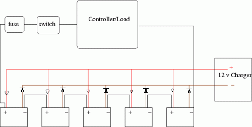
Drawing is what I attempted to see where I am screwing up :)
Please excuse the diodes, I need a better schematic layout program for Linux. EACH terminal to the 12 Volt charger is to have a diode to prevent pack current from shorting out across the parallel inter-connects.
IF I put diodes on all terminals in the appropriate direction, would it work? or does the charger require feedback current/circuit? I assume the circuit is one way.
I went over your the Series/Parallel switching thread, it seems to be trying to solve the same
problem. In your diagram "Bank Charging", can you replace/augment the fuses with diodes and remove the
anderson connectors?
Thanks,
-Todd
-Todd
Tronbike V1.0.3: Kawasaki Ninja ZX-11 Conversion
http://www.tronbikes.com
Todd, 4 of the 5 batteries would have been shorted in your drawing. However, looking at your drawing, I saw how an extra diode could be added per battery. If this works than it'll make me fell really stupid. This is interesting. I'll try it tomorrow.
I modified the drawing.

[url=/forum-topic/motorcycles-and-large-scooters/587-my-kz750-electric-motorcycle-project]KZ750 Motorcycle Conversion[/url]
[url=/forum-topic/motorcycles-and-large-scooters/588-fixing-my-chinese-scooter]900 watt scooter[/url]
Pic from http://www.electri
Unfortunately the revised diagram above is a direct short of the charging current. You'd still have to break the high-power series connections.
Also, the smart chargers do need a voltage as feedback. The only way I could charge a battery with a smart charger and a diode on the positive and negative was if the battery was in parallel with another battery direct connected to the charger. In that case, the current was taking an odd path. For some reason it didn't split evenly, and the battery direct connected to the charger got more charge and was like 1.6v higher.
If I removed the battery directly to the charger, but kept the battery with the diodes in the circuit after charging had started, than it stopped charging and displayed the fault code for being disconnected.
I tried a taper charger. Same odd current distribution. Also, when I connected the charger directly to the battery more current flowed, than when I went through the diodes.
[url=/forum-topic/motorcycles-and-large-scooters/587-my-kz750-electric-motorcycle-project]KZ750 Motorcycle Conversion[/url]
[url=/forum-topic/motorcycles-and-large-scooters/588-fixing-my-chinese-scooter]900 watt scooter[/url]
Pic from http://www.electri
If you replaced each diode with a battery isolator, or a small dc/dc converter (going for CHEAP on ebay), this system would work, due to the isolation of the converter.
i've got 12 isolated DC DC converters (48V-15V 100W) and a AC/DC supply (120/240AC 48VDC 32A) where I'll be putting one DC DC in parallel with each battery, and supplying with the AC/DC. Each one will have a board to do a 3 step charge, so it balances the pack. My point though, is that You NEED isolation for this to work, a diode doesn't do that.
Check out surepower. They sell isolators, but you should call them and ask if it works in series packs.
This is definately a problem that us EV'rs need to figure out.
____________
Travis Gintz
1986 Honda VFR Conversion
www.evfr.net
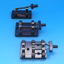
Since folks use terminal boards to make connections, is there a switch like a multible blade switch that you can use to just throw it from parralel to series and back for charging? Or wouldnt they be able to take the amps? could always make a cover so you dont touch it by accident etc.
I'm very new :) this would seem like alot of extra wires to me but would seem a simple thing to just throw the switch to charge and back to run once it was set up.
Picture I had in my head was a 2 way blade switch to go from one terminal board to the other...

Cross bar switch!
Andrew's plug design could probably be doable with a big enough double pole, double (or multiple) throw switch.
Browsing some marine electrical supply catalogs might be in order, though the amp ratings
are not that great...
http://www.sterling-power.com/products-diodes-info.htm
Maybe some big relays/solenoids to act as switches...could definitely be a "product" where each individual
battery is wired in, and any series/parallel connections are done from the box. Build/Sell it by channel where each channel = 1 battery.
Get on that Frodus ;)
-Todd
Tronbike V1.0.3: Kawasaki Ninja ZX-11 Conversion
http://www.tronbikes.com
haha, Todd, I'm working on something else... you'll definately like it... Can't spill too much more.
as far as the relays/contactors/knife switches...each time you add a contact point, you add losses... and voltage drop... not good for EV's
I don't see many pro's aside from the ability of automatic cell balancing in parallel.
____________
Travis Gintz
1986 Honda VFR Conversion
www.evfr.net
It looks like this will take a lot more than one double pole switch. I'm trying to work it out on paper, and it looks like it would take N-2 poles as the number of battery terminals, and half of those double throw. So, a 72v system with 6 batteries and 12 terminals would take 10 poles, and half of those would be double throw.
Can you draw up a diagram of what you have in mind?
[url=/forum-topic/motorcycles-and-large-scooters/587-my-kz750-electric-motorcycle-project]KZ750 Motorcycle Conversion[/url]
[url=/forum-topic/motorcycles-and-large-scooters/588-fixing-my-chinese-scooter]900 watt scooter[/url]
Pic from http://www.electri
I have an arrangment I'm in the middle of trying for my kid's 24v scooter, so that I can charge it with a regular 12v car charger. (Forgive me if I drew the diodes backward)
Using a normally closed relay to break the circuit when the 12v charger is applied would make this pretty transparent for my kids to charge it. (and not use any power during normal operation)
If this works at all, then it should be modular, with the number of separate relays necessary being one less than the total number of batteries
Safrole,
I think that will work. The issue will be feedback to the charger. Some weird things might happen. For example, a smart B&D charger won't even start. I tested a taper charger and the current flow was lower than if I removed the diodes. I can imagine this might impact charge time.
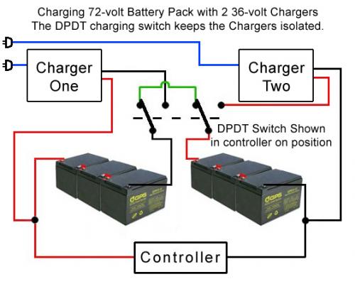
A simpler approach could be using a DPDT switch. With the charger connected to the main positive and negative, there shouldn't be any risk of damage if 24v on the output side won't harm the charger.
Anyway, please let us know how it works if you do the diode setup.
[url=/forum-topic/motorcycles-and-large-scooters/587-my-kz750-electric-motorcycle-project]KZ750 Motorcycle Conversion[/url]
[url=/forum-topic/motorcycles-and-large-scooters/588-fixing-my-chinese-scooter]900 watt scooter[/url]
Pic from http://www.electri
Here is an old setup I used that might give you some ideas for switching.

Grandpa Chas S.
but see, with that pack configuration, you need a contactor that will handle the full pack amperage. Just a little relay isn't going to cut it. You could use a DPDT contactor, but its going to be close to a couple hundred dollars for one that can handle 60-72V and 250A continuous/500 peak.
The Only way I know to truly isolate, is with a switching DC-DC converter that uses transformers inside it. Thats what vicors, and all the other ones out there do.
Just plan it out, and be safe, you don't want to cross wires, or have a short through the chargers and the pack.
____________
Travis Gintz
1986 Honda VFR Conversion
www.evfr.net
You are right this will not work but I did not post it as a solution only to give an alternative idea. BTW I used this on an e-bike at 25 amps and nothing more than a 15 amp DPDT switch for 2 years with no problems.
Grandpa Chas S.
Travis,
Reading about isolation properties of DC/DC converters here
http://electronicdesign.com/Articles/Index.cfm?ArticleID=4418&pg=1
indicates there is a level (voltage) of isolation that an isolated
DC/DC converter provides - did you do this with the Vicors or is it symmetrical/proportional
to the output of the DC/DC converter itself (48V/12V...)?
-Todd
-Todd
Tronbike V1.0.3: Kawasaki Ninja ZX-11 Conversion
http://www.tronbikes.com
Also, why 48V on the AC/DC output? For the 48v->12v converters?
I imagine its harder to find 12v->12v dc/dc converters than
it is 48v->12v converters?
-Todd
-Todd
Tronbike V1.0.3: Kawasaki Ninja ZX-11 Conversion
http://www.tronbikes.com
well, imagine a DC-DC converter, or an isolated charger as a battery in parallel with the battery its charging. It won't short anything out. Its just going to act as a parallel "pack".
But now, imagine if you take the - of one battery in a pack, and put it to the = on another, now you short it.
You need isolation, because you want to put a power source in parallel with the battery, and it has to be an indpendant isolated source or its going to short something. Non isolated converters use a common ground, and you can't use that.
I picked 48V ac/dc because I found some 48-15 converters (13 of them)... it matched nicely (32amps output, 1500W). I could have chosen a higher voltage, or lower, but I happened upon both at surplus prices ($99 for the AC/DC and 12 a piece for the DC-DC)... so it made sense. I couldn't afford doing it any other way.
All the 48V converters checked out ok, 4-5A a piece. Its an ongoing project.
____________
Travis Gintz
1986 Honda VFR Conversion
www.evfr.net
As fate would have it, the diodes were drawn correctly, if one assumes the coppertop end to be positive. The banded end of each diode goes toward each battery's positive and away from each battery's negative.
The arrangement seems to work, but there's fly in the ointment. It bleeds power. The NC relay I was going to recycle turned out to be worthless, (having a 120v primary) so I used a toggle switch instead. (The full amperage is of course not an issue in this little scooter.)
Maybe it's diode leakage or maybe it's the super-fantabulous speed controller from Bejing. It's not worth the effort for me to find out, since with the toggle set to "charge", it bleeds nothing whatsoever. Had I soldered on a relay, it would probably be dead with every couple days of storage.
One oversight is that I used single 3 amp diodes, so it will only bear the 2 amp rate on my charger. I should've run little parallel triple bundles for 9A rating, which would've allowed me to use the 6A rate on my charger. We ran it up and down the road a while (fat girls and mopeds...) and when I "charged" it a bit, the 6A rate warmed the diodes up pretty good.
Safrole, that's good that it works. The diodes bleeding power is something I either didn't catch or wasn't sure of.
I was thinking of using this setup on my motorcycle initially, but there's too many potential problems, and like you mention, the series interconnects need to be broken anyway. Another problem may be the negative voltage on the charger output. With more than 2 batteries and the series interconnects connected when riding, than there will be a negative potential on the charger output (or opposite to the charger potential when charging), and this might hurt the charger, but I'm not sure. This might require the charger being disconnected for riding.
Also power can't be used from the charger output which would be a nice advantage with a connector or DPDT switch setup. And, with a connector or switch setup the vehicle could be run with the batteries in parallel provided there's no controller LV cutout. This can't be done with the diode setup.
Even though this is a neat idea, I think it negates most of the advantages of rewiring or switching the batteries in parallel.
[url=/forum-topic/motorcycles-and-large-scooters/587-my-kz750-electric-motorcycle-project]KZ750 Motorcycle Conversion[/url]
[url=/forum-topic/motorcycles-and-large-scooters/588-fixing-my-chinese-scooter]900 watt scooter[/url]
Pic from http://www.electri
this would not work.
if voltage of chager is equal to the end voltage of one cell/battery.
only one cell/battery(at the most right-hand) will be charged, remainding cells/batteries will not be charged because the their voltages are lefted by the right-hand cells.
Li-ion Batteries Researcher...
LiPeO4 (LFP)...
EV...
use a transformer with multiple second coils and diodes will isolate the different potentials in the cell/battery string.
fulfil the task of equalization charge.
Li-ion Batteries Researcher...
LiPeO4 (LFP)...
EV...
I've had this working via PowerPole connectors, using a dummy plug to re-wire the pack as series for operation, and another plug that ties the 12V charger in to each battery in parallel for charging. It avoids multiple charger problems, such as varying cut-off points.
The maximum current draw is around 20 amps on my scoot, well under the 30A capacity of the PowerPole connectors I'm using, though you could get heavier capacity plugs for larger systems. The additional resistance due to the eight-fold passage through the plug and the extra 10ga wire in the path is quite slight, less than the original undersized 14ga "stock" pack wiring.
http://s200.photobucket.com/albums/aa122/mf70/Pack%20rewiring/
It's an either/or operation, though.
Mark