
A forum to collaboratively and openly develop repair and maintenance procedures for Vectrix Maxi scooters.
This forum / thread is not a manual yet and will possibly contain untested, speculative and potentially dangerous materials and errors.
This is part 2 - due to the many photos a single thread takes longer and longer to view, so I have to start over every now and then.
See http://visforvoltage.org/forum/3582-vectux-quotopen-source-vectrixquot for the immediate lead up to this thread.
Mr. Mik

Hi,
I have put the Vectux through some heavy paces today:
Battery drained to 5/17th within 33.3km by racing up towards Beechmont on a steep, winding road. (Just enough left to get up my driveway without "buSVLt" error message and/or incremental damage to the main fuse)
Basically pulling out of tight uphill turns with throttle fully open every 1/2 a minute or so for several km, then a few hundred meters straight and steep uphill at increasing speed at full throttle (it got to about 70km/h and was still rising).
Then a sniff test: No burning smell! The repair to the motor controller is holding up a treat so far.
The epoxy resin repair to the side stand is also hanging in well. Still feels better than the original due to the third washer.
.
Once I was at the top of Beechmont plateau I also hit some damaged road stretches which caused severe vibrations through the scooter. I have the tires inflated to the max specified on the tire, which is very slightly higher than the Vectrix recommended pressures of 40psi and 32psi (front).
No obvious problems caused by these vibrations, either!
.
The gear box now has a mix of Syntrax 75W/90 and 20% of Try Blu Oil Stabiliser in it.
http://www.autobarn.com.au/products/10/225/1732481
http://www.trubluoil.com.au/Oil_Stabilizer.html
It continues to be noisier than I like, worst at about 32km/h, but might last a long time anyway.
I'll just leave it for now and see what happens. The planetary gears appear to be so much softer than the sun- and ring-gear that they will probably not damage them for a long time. If the bearings get damaged by the bits getting pitted out of the planetary gears then so be it - the next logical step would be to put in new, possibly better bearings anyway!
The gear box got only a bit warm despite the heavy duty loads I put through it today; the motor was too hot to touch at the same time.
.
Here is a video compilation of drive-bys done today, at the beginning and the end of the 33.3km test ride.
There might be a slight increase in noise levels with a warm gear box, but not much.
Outstanding issues to be tackled when time permits:
--"Battery rework" as per recall not done yet. This might not be much of a risk because I keep my nose close to the action anyway and would catch any smell early. But it would be interesting to see the inner workings of the battery. Will read up on chargers.
--No access to CanBus software yet - will be needed sooner or later for all sorts of stuff.
--No display of real time current in and out of the battery or actual battery voltage yet (apart from during charging). Am slowly hack-sawing my way through a ferrite ring to make a Hall-effect based current sensor.
--Check out options for brighter headlights.
--regarding the gear box I will ride it around as is and try to find an engineering shop that can make plastic planetary gears.
204.6 Vectux kilometers so far!
Mr. Mik
This information may be used entirely at your own risk.
There is always a way if there is no other way!
Hi Mik,
just listened & watched the video. The video was slighty jerky and the fluctuating noise was in time with the regular pulsing of the video. May be due to the quality of the upload or something, I am on broadband 10mhz so should be smooth. Having said that, the noise your Vectrix makes is identical to mine. I am over 2000 miles now and the noise has always been like it is now. It is certainly much louder when full regen braking is used, which is no bad thing here as several times people have looked round just as I am about to blast them with the horn!! There are no jaywalking rules here more's the pity!!
As I understand it the battery rework was for the internal battery connections. As for chargers, most of the "smart" chargers I have come across use PWM (pulse width Modulation) and switched mode voltage reduction to control the charging rate.
Headlight power supply is limited, again, as I understand it by a straightforward switched mode regulator from the main battery bus. If you can squeeze more lumens out of it I think you'll be lucky. I found the lights quite adequate in winter over here for a cruising speed on dark roads of 40-50 kph. I 'll be very interested to see what you find. Hi power LEDS in a Series-parallel arrangement might work. You can get 3-5 watt LEDS now so that might be a way. I dont know whether a HID light would work but you can get those for Push bikes, although might expensive, they have relatively low power consumption.
Keep up the good work,
Regards
Ray
Ray
Thanks, Ray.
I already have a HID 35W set for cars.
The possible problems with it are:
* the "ballast" draws up to 10A during start-up (according to something I have read). It produces a high voltage and once it is running the power consumption should be reduced.
The DC/DC converter might not be up to that, but since the software upgrade which allows riding with both halogen filaments on we know that it can handle 70W continuously.
I need to put the HID ballast and lamp on the meter to see what it actually draws.
* the filament of the halogen lamp might be needed during the bootup sequence and the ballast might behave in a way that causes problems.
In that case the type of HID lamp which has a normal Halogen lamp for low beam and a HID for high beam might work.
I think the light will have to wait until I have some access to the CanBus in case I stuff something up in the process...
Mr. Mik
This information may be used entirely at your own risk.
There is always a way if there is no other way!
Just a quickie Mik. I knmow how to switch the headlight off but how do you get both filaments on simultaneously? I would also be concerned about the extra battery drain. It's a pity they didn't fit an external alternator/battery set for the lighting/auxiliary electrics, it would have been much easier.
The starting surge could be overcome by fitting a large capacity electrolytic capacitor across the DC power line. That would absorb the intial surge, or even a small auxiliary 12 volt gel battery float charged from the DC supply would do the trick. The battery idea would probably be easiest using a blocking diode to stop feedback into the DC/DC converter. There would need to be a switch of course otherwise the light would be on until the battery drained!!
Regards
Ray
Ray
Turn on scooter. GO.
While on low beam: HOLD the momentary high beam switch (pass switch?)for about 5s until the horn beeps once. Let go.
If you flick the high/low switch to high after that, both filaments will be on.
It only works for a few seconds if you are not moving, to prevent overheating of the lamp I believe.
It resets itself if you stop for more than a few seconds and if you turn the scooter off.
CAREFUL: Do not hold the momentary high beam switch for another few seconds after the horn beeps shortly - IT WILL TURN THE HEAD LIGHT OFF COMPLETELY! Not so good when you are zooming around in the dark at the time...
If this works or not depends on the software version installed in the Vectrix.
The power drain from 35W extra power consumption is probably negligible, less than 500m range reduction if both lights were on continuously.
The maths leading me to this assumption:
3700Whrs * 80%DOD = 2960Whrs
2960Whrs/42km range = 70.47Whrs/km range
35W * 1hr = 35Whr
Mr. Mik
This information may be used entirely at your own risk.
There is always a way if there is no other way!
The Vectux smells of smoke again....
I noticed it after a 20km ride home, high speed, 25degC ambient temp.
At least I already know how to take it apart and I have all the needed tools and gear!
Added a little later:
This time it took me only 1hr to get the motor controller out and the heat conducting paste off...not bad!
That took about a week last time, including cleaning the workshop and buying the needed tools.
The burning smell emanated from the same place as last time, but it is worse this time.
Maybe the heat build-up was not caused at the cable-connector interface at all, but inside the "black box" as I call it so far.
This time there is evidence of some melting at the bottom of the Black Box.
I guess I'll have to show more details of the board to get advice on how to open the two "Black Boxes", because I need to check and dismantle the connector(s). A bit of soldering on the surface is not fixing this one...
More soon.
Mr. Mik
This information may be used entirely at your own risk.
There is always a way if there is no other way!
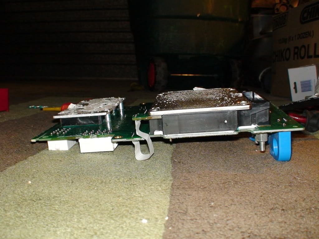
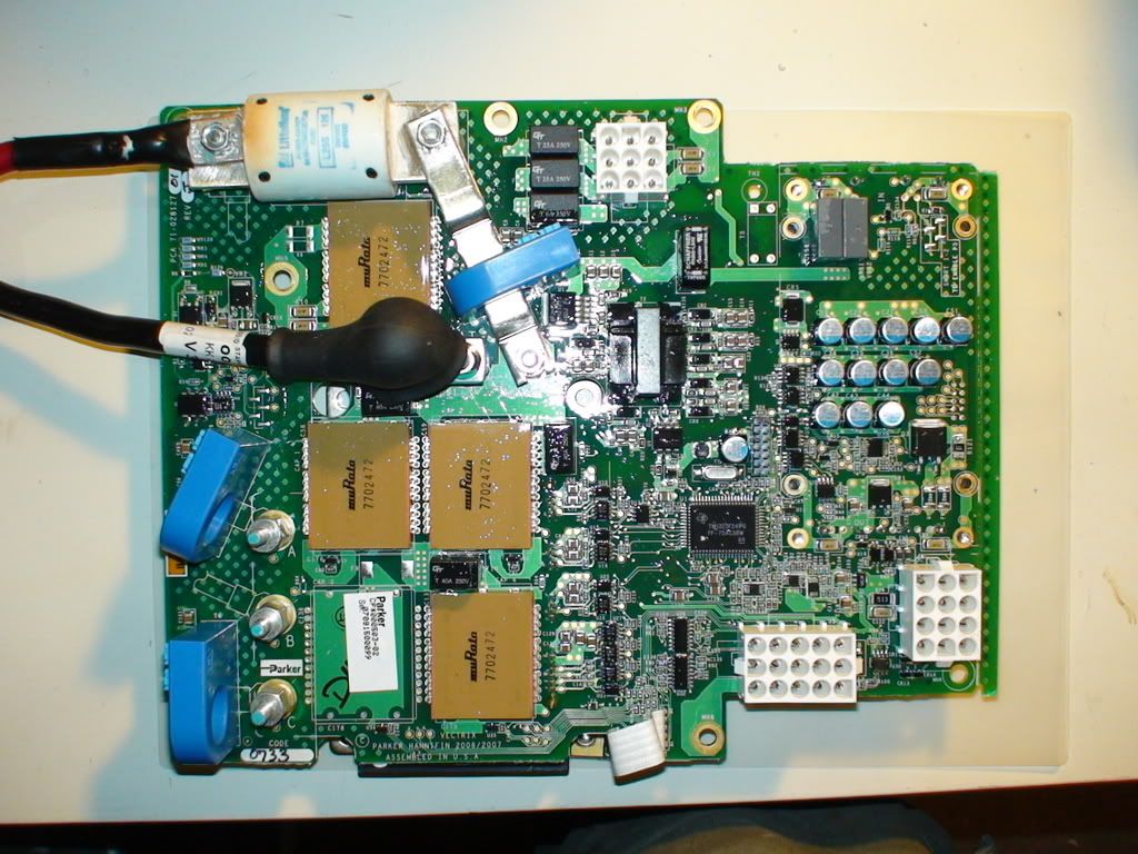
The photos in this post show the current problem on the motor controller.
The next post will show photos that help to orientate yourself on the MC board and to figure out how it works.
The big question is how to open the black boxes without doing damage, and how to PERMANENTLY fix the overheating at motor connector C.
And you can all bet on what is in those boxes....
Here are the pics of the current damage:
Click images to enlarge!
.
.
.
.
Mr. Mik
This information may be used entirely at your own risk.
There is always a way if there is no other way!
So, what is in the black boxes and how to open them without doing damage???
Ho can I replace the faulty connection with one that lasts for at least twice the expected remaining life of the Vectux? (I like to over-engineer...)
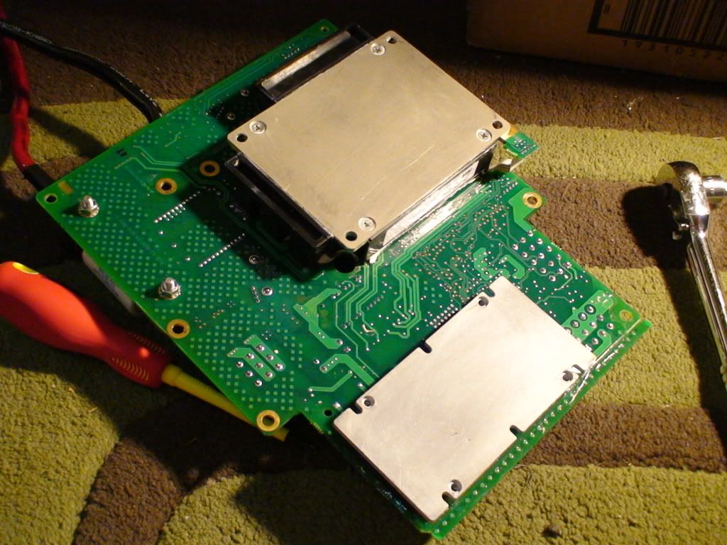
The following pictures have been taken during various repair jobs on the scooter:
Click on any picture to enlarge!
.
.
.
.
.
.
.
That covers the orienteering part of it.
.
Next: the close-up details.
Mr. Mik
This information may be used entirely at your own risk.
There is always a way if there is no other way!
Hi Mik
This may have something to do with the internal Battery connetion There recall was for .
If there is a bad connection in that line ,it will get the whole line hot . it will show up at the weekest point .
It is also the cause of most of the Ghosts in the electronic . giving it bad voltage ,the computor gets bad readings , and things get hot. like yours .
Seens you have made peace with Vectrix . You may want to email them directly in New Bedford Mass USA . or call tec. All the real tec that work on Vectrix for the last 12 years are there . They are go getter gaggit guys . Not sales men . they have seen and heard of most all the isuse . they may be willing to help. They may be reluctant to give too much detail info about the board it self . as there is other companys that are close to realeace Of EV Bike In the USA . But I would think they would what to help ,keep all the Bikes running.
Happy riding , Herb
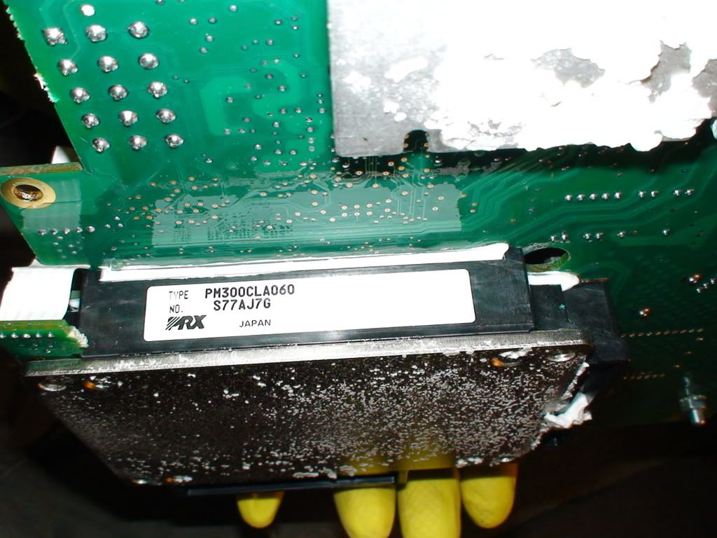
Hi Mik,
if you google PM300CLA060 it give the specifications of an inverter motor control module by Mitsubishi, it application:- General purpose inverter, servo drives and other motor controls. This appears to be whats inside the large black block.
The link:
http://www.mitsubishichips.com/Global/content/product/power/powermod/intelligentpmod/highspeedswl/pm300cla060_e.pdf
Something is definitely not making a good connection in there or it is failing. It is an encapsulated module so I don't think you'll get inside it without damage.
Good luck mate,
Ray
Ray
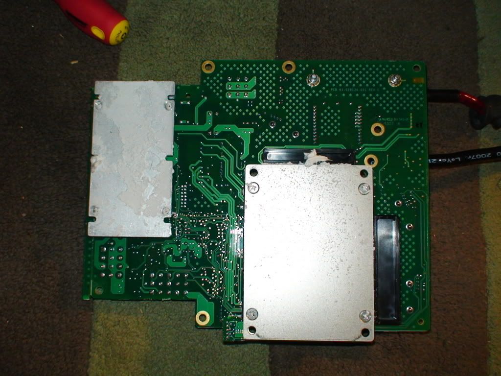
This one helps to identify what is inside the black boxes:
.
Once the upload has finished I'll make that folder with the above pictures on Photobucket public, so you can view the other high resolution pictures of the motor controller.
It might take me a while to edit them, make thumbnails and put them on here.
Mr. Mik
This information may be used entirely at your own risk.
There is always a way if there is no other way!
Thanks, Ray!
I meant to google that weeks ago and now I really wish I had.
The link that you provided is exactly to the right spec sheet; combining that with what I know already makes it clear to me that the repair job I did could not succeed.
One of my questions, which I could have answered myself by googling, was if the current needs to go down the sleeve underneath the copper plate. Of course it does...
And that is where I believe the problem lies:
The same black gunk that stops good contact between the washer and stud and copper plate at the top will also sit between the copper plate on the bottom of the board and the silver contact on the "BB 1".
And because top plate and sleeve disintegrated a bit, there will always be resistance there until I get rid of that damaged part of the board. It was most likely damaged during reassembly after the fuse replacement, because no torque wrench was used. This would have compressed the copper sleeve in between the copper rings on top and bottom of the board and broken the continuity between them, causing resistance and heating up.
The fix:
Remove the burnt part of the board, clean up the contact on the IGBT Black Box and connect cable C directly to it.
Stay tuned for results....
And the Folder with the Vectux Motor Controller pictures is now public, there are many more photos in there.
http://s281.photobucket.com/albums/kk217/Mr_Mik/Vectux%20Motor%20Controller/
Let me know if anyone can work out what is in the Black Box 2, please!
Mr. Mik
This information may be used entirely at your own risk.
There is always a way if there is no other way!
Any numbers or anything on it Mik? I am heavily into electronics (as you might have guessed!) and may have other sources than google. Let me know what you find.
Regards
Ray
Ray
Nothing to be found, just a black box...
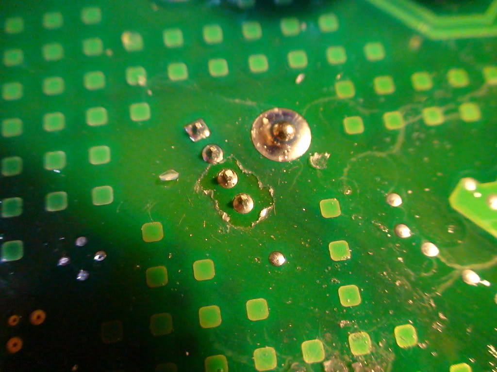
The connector C now looks like this: (Click to enlarge, as usual)
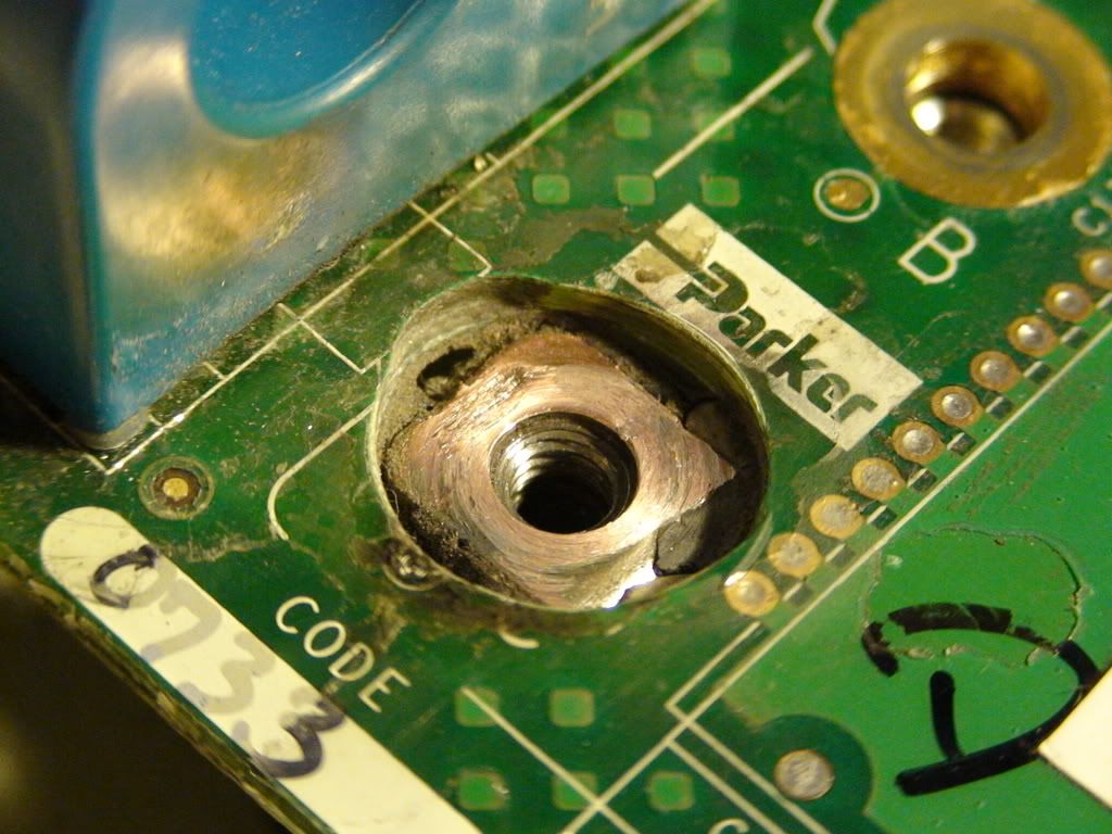
It was difficult to tell where the copper from the underside of the board ended and the connector below it started. They appeared to be bonded together with a layer of silver material, either solder or silver, or silver solder??
I ended up grinding a bit too far around 0900 o'clock. Either the silver layer was thinner there or I was not careful enough, probably both!
I wonder how to best create a good connection to the stud.
Is polishing the copper surface better than a layer of solder, or polishing and then solder?
Are the silver pen products any good for this?
I bought a soldering station with temperature controlled 60W soldering iron today, in case I need to go yet another step further and de-solder this golden row of pins to get the IGBT Box off the board:
Also have plans and materials to make a current display for the dashboard.
Mr. Mik
This information may be used entirely at your own risk.
There is always a way if there is no other way!
I'm not sure that was a good idea Mik. You may find the brass sleeve was required to for a connection through the circuit board for a connection to circuitry on the other side of the board. If there is no pcb connection then fine.
I would use metal to metal with a spring washer between to cut into both surfaces ensuring a good electrical connection. Solder would need to be perfectly flat and again, at these high currents the resistance is too high. Silver paint has too high a resistance for this sort of work. Its Ok for repairing windscreen heating elements but thats about it.
Before you remove the module, try and get hold of a solder sucker (I think you said you had one anyway) with a silicon nozzle and make sure it is absolutely perfect working order suction wise. They can deteriorate with age and can lose the suction. Practice on a spare pcb from an old computer first. Desoldering braid is also a good idea. Once the module is removed then you can check to see if there are any copper pcb connections form the underside of the stud to the rest of the PCB.
Regards
Ray
Ray
I checked for connections with transillumination before hacking through the board - nothing connected there.
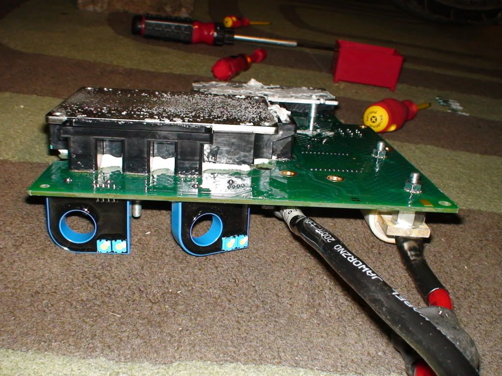
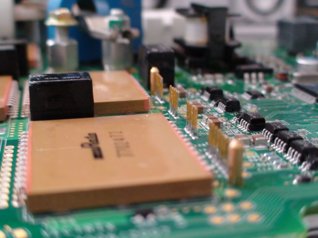
It is also clearer to me now how this IGBT unit works - the pos and neg cable go in on the one side, the three motor phases out the other.
Any direct connection to that amount of current and voltage would destroy the other board components. The electronic fine control of the IGBT is done through the golden connectors on the top (groups of 3 x 4 pins for each phase, the group of 7 for general stuff.
The current measurements are done through the Hall-effect sensors (blue) around the pos battery cable and the motor phases A and C cables.
http://www.aceisys.com.my/DataSheet/Lem/HTB%20100-TP.pdf
The ones in the Vectrux are all LEM HTB 200-P.
I plan to take voltage measurements from the Hall-effect sensor around the pos battery cable and connect it to a high impedance digital voltage display (initially a DMM) on the dashboard. Pin 3 (Output) is where I will solder on one cable, and probably Pin 4 (0V) for the other (see above link for diagram of the sensor. The pins are accessible on the back of the board).
.
.
Would you use a spring washer on each side of the metal washer? The original setup has only one spring washer between the stud and the metal washer.
I am also puzzled why everything is made of copper (good conductor), but then a steel washer is put in between the copper parts where they get connected.
Probably because copper cannot work as a spring washer.
I'll try to get a 2mm thick copper washer and steel spring washers for both sides of it.
That should also use up the extra space freed up by the missing thickness of the board.
Would polishing the connector to a mirror finish allow better contact or is this irrelevant if the spring washer digs into it anyway?
.
I'll try to get away without removing the IGBT box, but have bought desoldering braid just in case. And I have two solder suckers because I found the old one right after buying a new one...
Mr. Mik
This information may be used entirely at your own risk.
There is always a way if there is no other way!
I... I can't look at those pictures... without... crying...
Then, reading your posts...
Somebody make him stop!
<table border="0" style="border:1px solid #999999; padding:10px;"><tr><td>
<a href="http://www.BaseStationZero.com">[img]http://visforvoltage.org/files/u419...
[size=1][color=black]www.[/color][color=#337799]BaseStationZero[/color][co
Of course you would prefer the AU$2500.- replacement board approach....
There will be more sobbing ahead for your kind!
Reduce, REPAIR, reuse, recycle!
Maybe try peeping at the pictures through your fingers.....
Mr. Mik
This information may be used entirely at your own risk.
There is always a way if there is no other way!
Oh the humanity!
:P
<table border="0" style="border:1px solid #999999; padding:10px;"><tr><td>
<a href="http://www.BaseStationZero.com">[img]http://visforvoltage.org/files/u419...
[size=1][color=black]www.[/color][color=#337799]BaseStationZero[/color][co
Mik,
I would try and get away with using just one spring washer between the stud and the connector. Any other washers are going to increase the resistance. Make sure the threads of the stud are also perfectly clean to improve the metal to metal contact. Keep any mismatch of metals to a minimum. I learnt a severe lesson here. I had just finished my apprentice ship as an aircraft electrical engineer. Before I was allowed to actually work on the aircraft I spent some time in the servicing bay, refurbishing the aircaft generators, 28v 200amp jobs. One stud on the brush gear was sightly worn. To restore the length I used a steel washer. Fortunately we did a full load load test before re-fitting to an aircraft. After 15 minutes on full load there was a horrid smell of burning and then the test rig shut down. Opening the generator casing was difficult becase the brush gear where I had fitted the steel washer had melted completely. My boss although very acerbic about not using the correct procedure said let that be a lesson to you. YOU might not be able to measure any resistance but 200 amps at any voltage will!! Needless to say I spent the next week making tea and taking flack!!
Regards
Ray
Ray
I can then use the original spring washer instead anything out of the array I bought today...
The original spring washer and the flat washer do not change shape like the copper does, neither does the stud. So I fail to see what the flat washer does, other than protect the surface of the PCB from getting scratched and increasing resistance a little bit.
I have new steel washers and spring washers but will leave them in their bag after your comments!
The only problem with this is that the stud is too long now due to three factors:
* missing flat washer
* missing PCB thickness
* molten and re-hardened black box plastic in the area under the nut. That stuff is amazingly hard. I will have to grind it out without damaging the threading in the nut.
Cutting off the stud to make it fit is not a good option because if I end up buying a new IGBT black box I will need the original length on the stud; and the right stud in the right alloy might be next to impossible to find! So I'll avoid destroying that stud for now.
I'll use a globe shaped diamond cutter to remove the plastic in the way without touching the thread of the nut above it.
Everything will be polished before reassembly and I will not apply PCB lacquer this time, because this might also be a reason for the failures (It might melt when the connector gets hot, then creeps into the gaps and hardens again. Just a guess though.)
There is little risk that condensation/moisture is going to cause trouble in that spot because of the heat from the IGBTs drying it out (I hope).
Thanks for your invaluable input, Ray!
Mr. Mik
This information may be used entirely at your own risk.
There is always a way if there is no other way!
Does anyone else think these are 82µF capacitors?
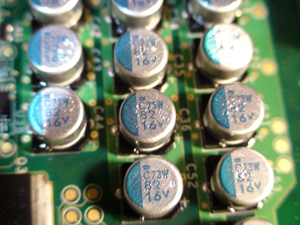
If this is correct, then there are 13 * 82µF = 1.066mF more on that board than I used in my calculations (0.88µF) for what resistor to use for the battery reassembly.
Only out by a factor of 1211!
I have a variable resistor to put into the bridging cable instead of the 8Mohm resistor for when the batteries go back together next time.
Can anyone tell me how to get a "micro" symbol into the text on V?
Thanks Arctic Fox! µµµµµµµ
Mr. Mik
This information may be used entirely at your own risk.
There is always a way if there is no other way!
Again resistance , as Ray said the washer was the week link . There is a Know fact that keeps getting left out . the bad conection inside the battery . All the wiring will hot . and melt thing that would not usally be hot.
AS the stater cable on any car the conection at the Battery will be bad . but it melts things other places.
Also mik has ben talking about the head light . one of the other people that voided his waratty .change him head light . it fryed the tail lights . prossed with cation. I do not know why they are linked so that would happen ,but it did.
Good luck ,Herb
They are not linked.
As far as I know the tail lights fail for some reason inside the tail light, I know of three such failures.
I believe it was coincidence that it failed when the headlamp was changed. The headlamp circuit can handle 70W, and LAVectrix had a 55W globe in there if I remember rightly.
Chances are that the failed tail light was NOTICED during the front light mod, but had been broken before.
Mr. Mik
This information may be used entirely at your own risk.
There is always a way if there is no other way!
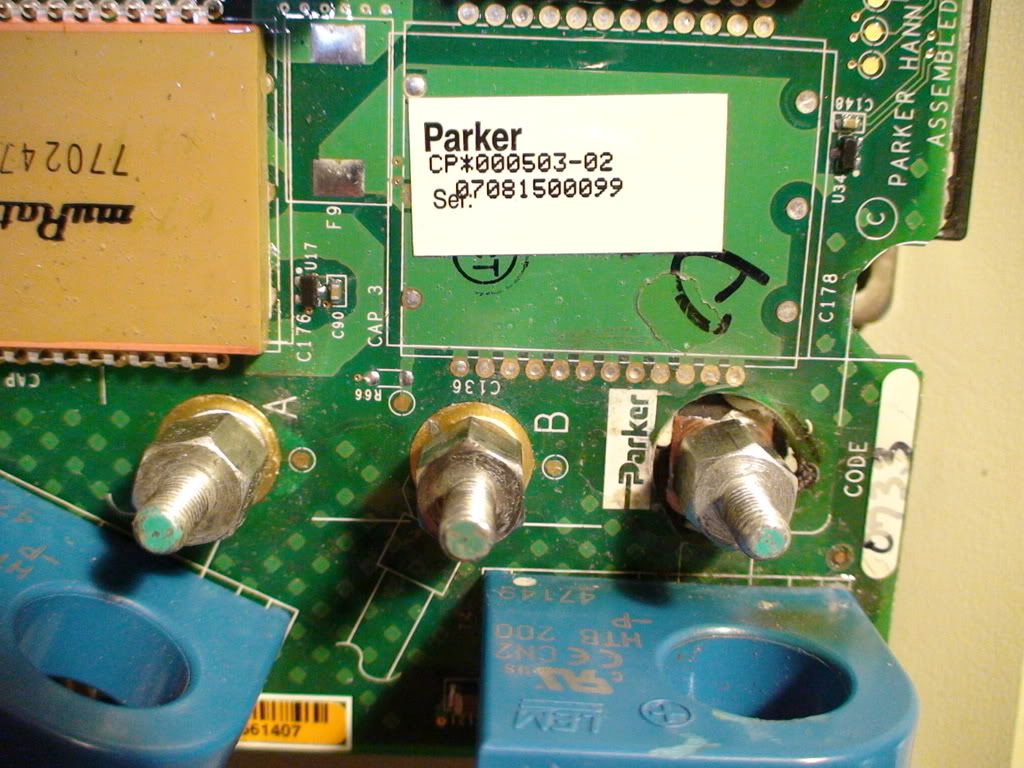
It appears most or all of the high current connectors are silver coated.
At 0900o'clock: undamaged Vectux spring washer from motor phase B cable.
At 0100o'clock: darkened spring washer (despite polishing) from motor phase C cable. I suspect the washer might have been red hot during the over heating problem.
At 0500o'clock: A new steel spring washer.
.
.
.
The good stud from motor phase B and the damaged stud from phase C. Note the silver coating has come off in places.
.
.
.
I have placed the darkened (despite polishing) stud from phase C in position of phase B, with a new steel spring washer and the original flat, silver coated washer.
.
.
.
The lug of the phase C cable needs a bit of bending to reach the stud in it's lowered position. I mounted the good stud from phase B with the good spring washer from phase B in the phase C position, no flat washer. If the actual stud is the problem (maybe due to the damaged coating), then the overheating should now happen at phase B instead. I expect it all to go well, though.
.
.
.
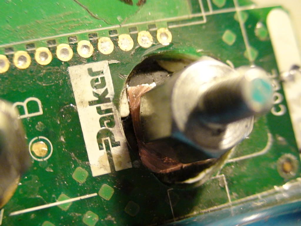
Hoping that this will be the last time that I have to remove the motor controller for a loooong time, I did a little "mod" whilst I have it out:
.
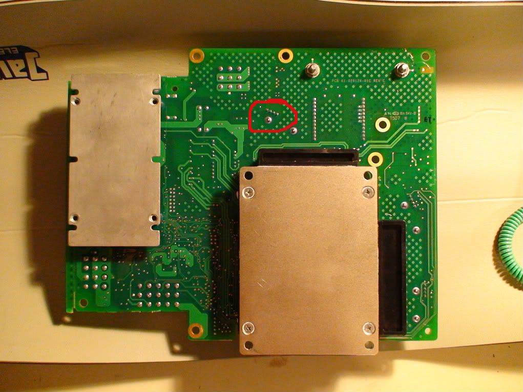
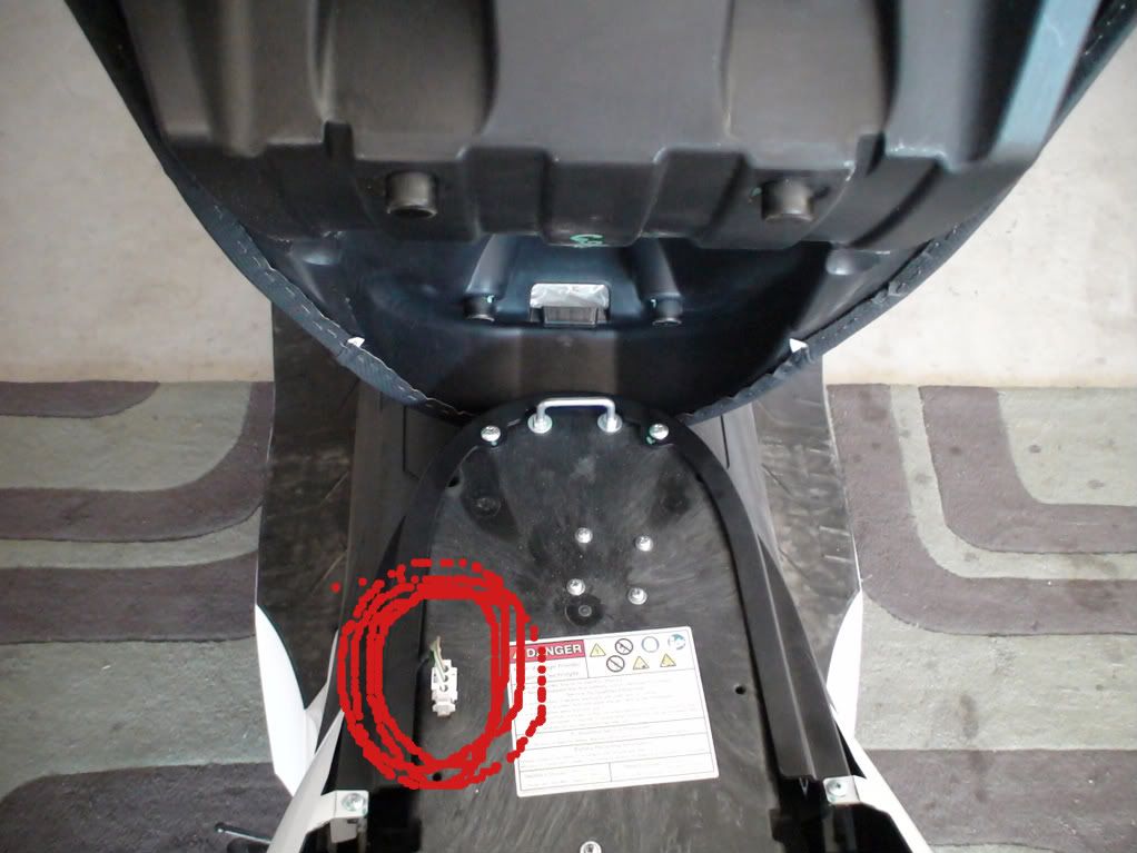
Circled is the position of the pins of the Hall-effect sensor around the main positive battery cable, just after the motor controller fuse.
All power in and out of the battery goes through there and I hope to get access to real time current data during driving (including regen braking) and charging by tapping into the output of this sensor......
Arctic Fox, LOOK AWAY NOW, I'LL BE SOLDERING AGAIN!! AND I WILL USE A HOT GLUE GUN ON THE PCB - YOU MIGHT FAINT IF YOU ARE NOT CAREFUL....
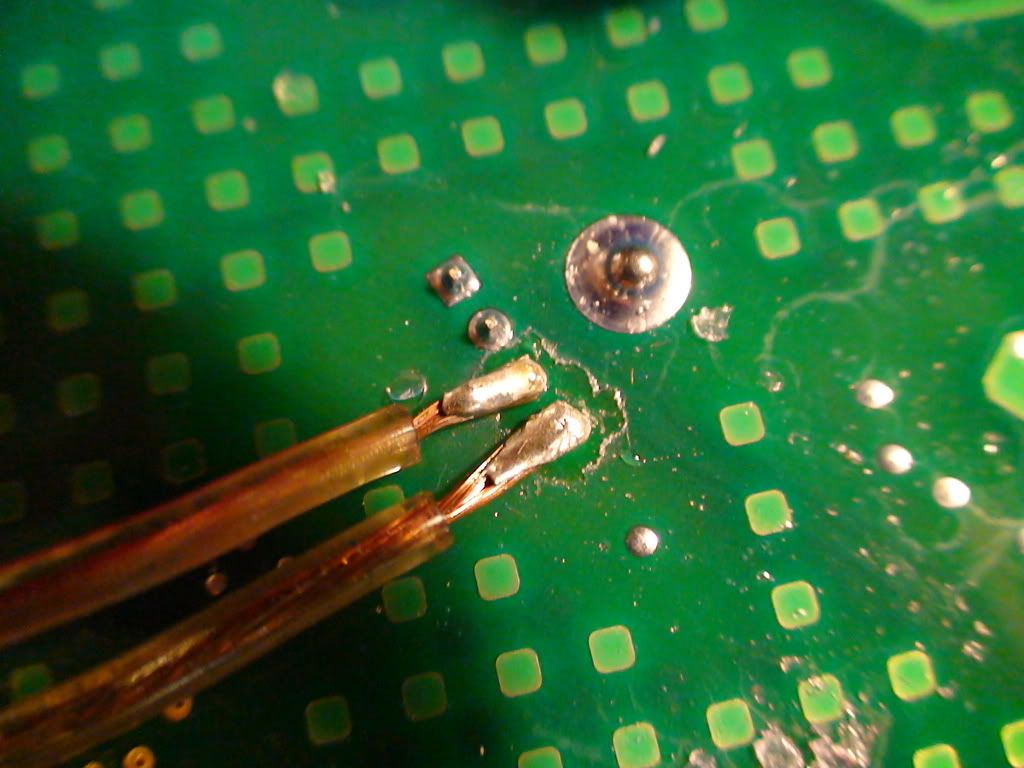
The soldering did not go too well until I scraped off the waterproofing coating (the whole board is covered with a clear shiny film).
The lacquer spray I bought (to patch the holes I am making in the coating) claims that you can solder through it, so I assumed that might work with the Vectux PCB coating too.
But no such luck, at least not with my soldering skills!
I scraped the coating away from pins 3 and 4 and cleaned it with PCB cleaner.
Then the soldering worked:
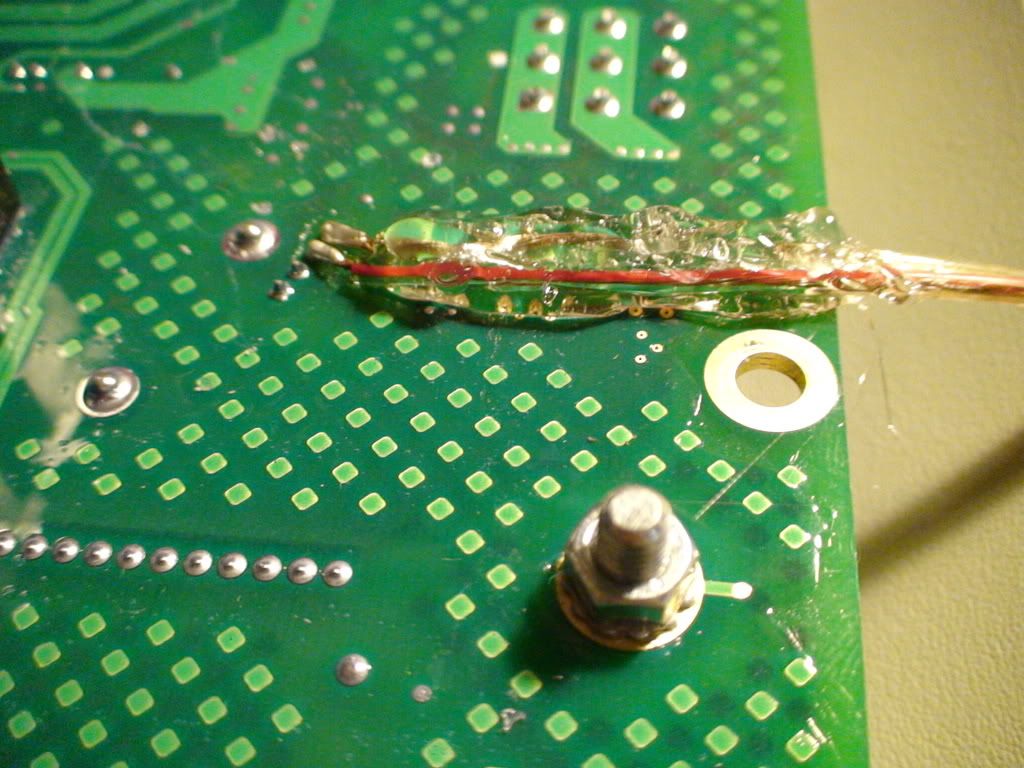
.
I glued the cables to the back of the PCB because the nut you see just underneath it is connected to the main fuse and can deliver 125A before it blows...better stay away from there.
.
.
.
I plan to use a DMM initially and the replace it with an LED display if it works the way I expect it to.
Mr. Mik
This information may be used entirely at your own risk.
There is always a way if there is no other way!
& # 1 8 1 ; <--- without the spaces = µ
µF
"clear shiny film", non-wetting solder, no tinning?
I think I'm.... I'm... oh my... #$%^!@_________________
:D
<table border="0" style="border:1px solid #999999; padding:10px;"><tr><td>
<a href="http://www.BaseStationZero.com">[img]http://visforvoltage.org/files/u419...
[size=1][color=black]www.[/color][color=#337799]BaseStationZero[/color][co
Thanks AF.
µ put in by using code "&# 181;" looks the same as just pasted: µ
Looks like I can just copy and paste any needed symbol as long as I can find it somewhere else on V.
Or is there a page somewhere with all those cryptic codes in one place?
The clear shiny film covering the PCB is probably not lacquer, but I cannot yet distinguish the different products available. It is softer and thicker than most lacquers I have seen, more like thin layer of clear rubber.
It does not glow in the UV light of my mozzie catcher but it is fairly easy to see where it is anyway due to it's thickness.
Mr. Mik
This information may be used entirely at your own risk.
There is always a way if there is no other way!
My Vectux is up and running again!
A test drive was not yet possible, but it behaves well on the rock.
The voltmeter shows 0.21V during early charging when it is connected to the cable coming from the Hall effect sensor on the MC board.
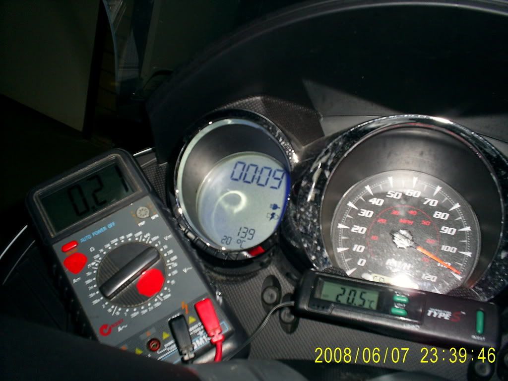
It also shows up to 3 V when revving the motor on the rock, just like expected!
And minus when amps leave the battery, no minus when they go into it!
Hip Hip, Hurray!
After a test ride (or a few) I'll install a LED display on the dashboard; need to find out what range is needed, particularly what the max voltage will be.
The LED I have should be able to run off a USB (5V) power supply that plugs into the 12V outlet in the glove box. Or I'll put in batteries if that does not work.
Water proofing the display might be a nightmare - I might just keep it in the glove box like the thermometer when the weather is not so good.
.
.
Some lessons learned:
Scraping the heat transfer paste too thin is not good. The metal plate on the Black Box 2 did not make contact in the middle, it is not straight enough. I put more paste on this time.
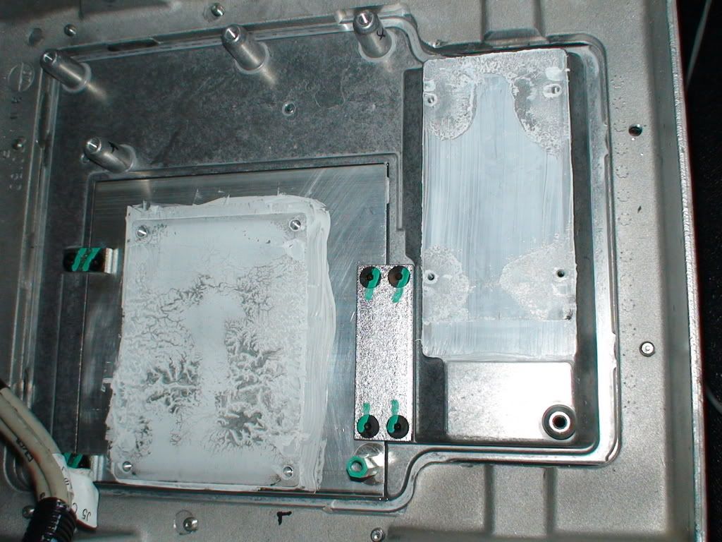
.
The charger starts and runs apparently normally when the battery cooling fan connector is disconnected and the fans do not run. The charger fan under the front fairing still runs but is much quieter then the battery cooling fans. A switch could easily be installed to turn the battery cooling fans off when not needed in really cool or cold climates. A much better option would be to turn the fans off via the CanBus when the temperature is low enough - a project for later on!
I have not tested this for more than a few minutes - watch it like a hawk for at least one full charging cycle if you decide to use the 30sec procedure to disconnect the battery cooling fans.....
It's only 12V going through that connector. There are two fans in the black box under the connector.
.
.
Mr. Mik
This information may be used entirely at your own risk.
There is always a way if there is no other way!
The test ride went very well!
Voltage readings from the "real time real world" ammeter range between about -4V and 2V.
More detailed analysis and videos to follow soon!
Mr. Mik
This information may be used entirely at your own risk.
There is always a way if there is no other way!
Greh. You do the "µ" thing weird. I hold alt and then punch 230 on the keypad. "Ω" is 234. 248 ("°") is a good one, too. 224 and up are the more useful codes. ☺
Hot glue rules, BTW. :P
The author of this post isn't responsible for any injury, disability or dismemberment, death, financial loss, illness, addiction, hereditary disease, or any other undesirable consequence or general misfortune resulting from use of the "information" contai
Pages