Hi all -
I'm still working through the problems with the lamps on my bike; it ended up not being the dc/dc transformer, so XTreme is sending me out about 5 different parts to swap out. I'm glad that they really stand by their warranty! (and, on the plus side, I'm getting free spare parts!)
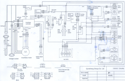
During our conversation, John over at X-Treme threw the wiring diagram for the XB-600 to me, and now, I'm sharing it with you.
I hope this helps out some of my fellow volt-heads.
Regards,
-Mark
PS: One very curious thing in this diagram is in the lower-left, there is a connection that says "speed adjust holder". I wonder if there is anthing connected to mine...


Hey, thanks for sending that along. Course I'll have to look...seems there's a diagram in that excuse for a manual that came with the scoot! But I don't think it was this complete.
Hey, did you ever get the battery drain situation worked out?
Gushar
Gus
Cool, thanks, Mark. BTW, the "speed adjust holder" is a poor chinese translation for throttle. LMAO!! I remember tracing the red,green and black wires to my throttle when putting on the 72v controller. :)
Hope you get your lights figured out.
Keep the rubber side down and the shiny side up.
Forgot to ask, did you replace your shunt and get your voltage drain straightened out?
Keep the rubber side down and the shiny side up.
Thks a lot for sharing this !!
But I have more wires coming out of the controller than on the plan! I still have two unidentified plugs. One red plugs with five wires(white, black purple, orange, gray) and one yellow plug with white and black wires.
Any idea on what these are for ?
thks a lot !
this forum is full of information !
William
Is it possible that the red plug with 5 wires is for the keyswitch ? Maybe it is for accessories like the alarm system ?
any idea ?
May be be a newly improved ver.The only five prong connector on my controller goes to motor for Hall effect signaling .Wish they had included a fan control plug close to the controller.DC-DC converter makes Black wiring the active leg on switches . Ongoing controller fan modification !!!!
Hi !
I am converting an old Luyuan 48v bike((Luyuan seems to be the factory where it was build)) that look similar to the Xtreme Xb series with Xtreme parts. I bought a xb-600 motor, controller, speedometer, and throttle.
I have been able to connect everything so that the motor spins ! Thanks Again Mark for sharing this wiring diagram !
But I have one more question :)
What can be the value for the two diodes that are in parallel just before the two brakes switchs ?
For my test I replaced the diode with two Leds(with resistance) that were in the old speedometer and the motor respond to the brake. But i'm not shure what will happen with those leds when I will get a working 48v to 12v converter ! For durability I would prefer get the right Diode Value than keeping those leds
Anybody has the Answer ?!
Anybody know what these two diodes are for ?
Thks a lot !
I love this community !
I wouldn't use LED's, but any general purpose utility diode should work fine. The current passed through the brake switches (and thus the diodes) is very low. Just go to Radio Shack and ask them for a couple of inexpensive utility diodes. Nothing fancy, just the little glass ones that you see in electronics bins by the hundreds.
For whatever is valued there goes my humble contribution : Accepting that the bike is not grounded , the diagram seems to indicate that there is an unrestricted flow of current (from DC 12 + {positive} thorough everything -accessories - except speedometer and battery charge .Those two use good old + 48v. So there would be 12 v flowing from the rear light except those diodes don't let it happen . In fact . the handles ground the controller stopping the motor .Also let the -48v flow to the rear light . Hope this help.P.S. Meant the switches(for everything else) act on -48v not on +12v.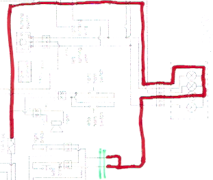 No switches cutting +12v . Can't have feedback running into controller by either blue or brown.Black & yellow must be Negative ??-48v since it (even if lights are not on) activates rear brake lamp.
I bought big black diode rated 3 amps and a few hundred volt. I think I will get smaller one cause these are too hard to weld lol.
But since you seems good with electric current I will ask you another question :)
The Bike I am converting with Extreme parts had 2 battery packs. One rated at 14amp/hour and one at 7amp/hour. Can I put the two battery pack in parallel to get more amp to the controller ? Even if they are not rated at the same amp/hour ?
thks !
Yes, but the 7amp hour pack will run down sooner.
Keep the rubber side down and the shiny side up.
In my experience, putting batteries in parallel will discharge then equally. Of course they have to be the same voltage. As for example, the smaller 7 amp battery gets lower, it's internal resistance goes up, which will cause the load to automatically balance to the larger battery until it drops a bit, then the smaller battery pics up some extra load. All this is happening in an analog world, so you can't actually measure it. In other words, when the set of batteries is finally dead, they are all dead, and will all need to be charged. This is unlike putting batteries in series, where a smaller battery will increase its internal resistance to the point where it will actually reverse polarity, and the whole string will be useless, even though all the larger batteries are still charged. Putting batteries of different sizes in series is generally not a good idea, since it will likely lead to the destruction of the smaller battery.
Just my thoughts,
Tom
Do you have a current link for that circuit diagram? Original shows as "Firefox can't find the server at www.markmilley.com."
Mark
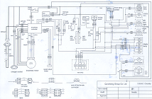
Here is the diagram. Sorry it took me a bit to find it. I can't believe I still had it saved.
Keep the rubber side down and the shiny side up.
That's the one. Can you post one that's more than 212 pixels across?
Thanks for the prompt response. I managed to shred the one that came with my manual. (DOn't ask.)
MF
Here you go:
Hope this helps.
-Warren
Keep the rubber side down and the shiny side up.
Hey Warren, ltns! Was starting to think you had gone 100v and flown off a corner somewhere! lol
There's a couple of new XB 600 owners wanting to do shunt and volt mods, asking how they can see the pics on your page. I had a look and sure enough they are gone. Maybe when they changed servers here a few months ago, they got lost or something.
So how you been, and hows your bike doin? Thanks to you and a few others I've been riding the 72v mod for over a year now and recently I picked up a 45v 800 watt 750 rpm motor with controller. The performance was great and of course I had to then mod it. Now the ride is incredible. I wrote it up here with a few pics:
http://visforvoltage.org/forum/9897-72v-37mph-xtreme-xb-508
Mike - Oregon XB-508 with after- market 800watt motor and 72V upgrade
(Thanks to Member tips on V is for Voltage!)
Starting another thread on the XB600 circuit...
Eagleeye, here are the pics of the shunt mod.
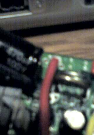 See the bigger coathanger shunt soldered over the smaller factory shunt? I think I used a 1 1/2 inch piece if I remember correctly.
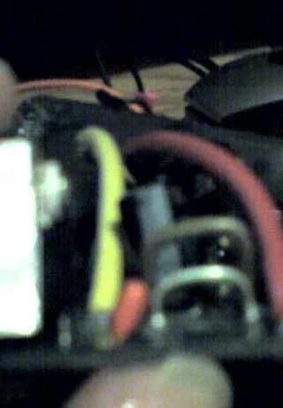 Closer view. It's hard to get a clear shot of the small stuff.
Here you can see that the holes for my shunt were drilled right next to the stock one. Hope this helps you with your shunt mod.
Keep the rubber side down and the shiny side up.
Sorry, the editor cut the pic of the back side of the controller off. Here it is
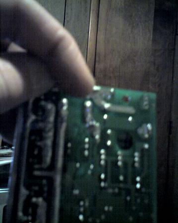
Keep the rubber side down and the shiny side up.
Zerogas,
Thanks a lot!
What about replacing the mosfets and capacitors, or is that not necessary?
Eagleye