FWIW, I want to share some photos of my bank charging scheme and installation of a Cycle Analyst (stand-alone version).
After reading through several debates here in the forums, I decided that 10 leads (one to each battery terminal) is the method that I wanted to employ.

I mounted a 10-position screw terminal strip to the back of the main battery box to provide a convenient termination point for my cabling. I would have preferred using the DIN style terminal blocks with setscrews as I see someone else already has done, but I already had these terminal strips laying around from my model train layout. The connectors used to interface with my chargers (Vector 2-4-6) are 6-pin MOLEX connectors that I found at Radio Shack.
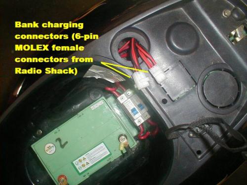
One of these connectors simply uses only 4 of 6 available contacts. I still haven't taken the time to make a mounting plate for these connectors, they are still loose under the seat. Save yourself the aggrevation that I went through - solder the wires to the pins on these connectors. They are a pain in the @$$ to diassemble for repairs, but it can be done with patience.
I mounted all 5 of the Vector chargers plus a 6-outlet switched surge supressor outlet strip (read: fancy extension cord) onto a scrap piece of shelving that I had lying around the garage.
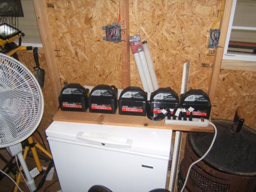
I then cut the original aligator clips from the cables and hard-wired the outputs to mating MOLEX connectors. My cabling was all color-coded black and red, so it was a pretty simple no-brainer to accomplish.
The resulting umbelical cord is approx. 7 feet in total length, allowing me to place the chargers out of the way on a shelf under my workbench and still plug into the scooter for charging.
The Cycle Analyst is quite simple to interface to the scooter. After making some custom brackets from some scrap sheet metal I squandered from work, I mounted the "head unit" to the top of the instrument panel using standard machine screws.

I replaced the original screws that held the case together on the CA with longer and slightly larger diameter versions, allowing me to attach the brackets directly to the case without modification.
The speed sensor is mounted using small, 5-inch black cable ties to the inside of the front plastic fender.
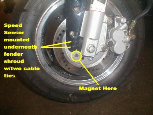
Look closely at the photo and you'll see the cable ties wrapped through small holes that I drilled through the plastic. The cabling for this sensor is routed down through the front fork housing, parallel to (and loosely wire tied to) the front brake hose. There are two magnets supplied with the CA, one is neatly mounted on a spoke clamp and the other is simply a loose magnetic disc. (I understand that this seperate disc was meant for use when a stronger magnetic field is needed due to distance from the sensor). I attempted to mount the spoke clamp magnet through an unused mounting hole on the front brake rotor, only to find that the magnet housing would rub against the the disc brake mounting bracket. I was in the process of drilling/countersinking that same hole in the rotor when it dawned on me: use the seperate, small disc magnet that was also supplied with the CA. As luck would have it, that magnet fit neatly into the hole I was creating on the rotor. I didn't even bother using any adhesive - just let the magnet do what it's supposed to do and stick itself in place. The total distance between the magnetic disc and the pickup sensor is approx. 3/16" - more than the manufacturer suggests, but it works reliably.
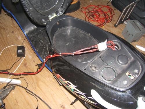
Next I routed the current shunt assembly through the body of the scooter. There is just enough cable between the head unit and the current shunt to reach to the front of the battery compartment (under the seat).
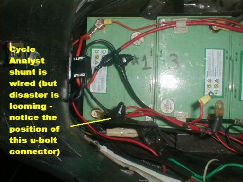
Since the heavy-gauge wire leads on the current shunt are so short (only 3 or so inches long) and I didn't feel comfortable trying to crimp/solder lugs onto them, I opted to use split-bolt clamps from the electrical aisle of my local Lowes. I used two short pieces of 6AWG stranded copper wire to complete the connections needed. The new battery terminal connections that I had to create were crimped and soldered directly to the cables, again from my local Lowes.
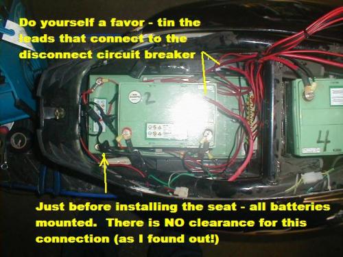
After connecting it all the first time, I realized that I provided no method of turning off power to the CA - so I re-wired it again to take advantage of the battery-disconnect circuit breaker.
The following step should only be undertaken by highly-trained professionals such as myself. To increase the conductivity between the battery terminals and it's attached cabling, I opted to weld the connection together.
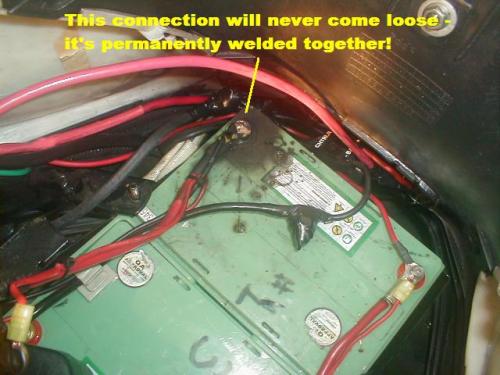
This was accomplished by pinching one of the split-bolt connections between the bottom of the seat and the negative terminal of the battery labelled #1 in my pictures. The actual welding process occurs when I placed my 250-something pound butt on top of the seat and the sparks started flying! The saving grace to this episode is that the connections at the battery terminal were final and tight - so I won't have to worry about them coming loose until it's time to change batteries in the future!
There does not appear to be any damage to the battery other than cosmetic burning on the case - no leakage and it was of very short duration (less than 5 seconds total time) with no obvious battery performance issues.
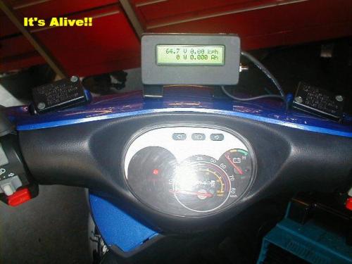
Initial setup of my CA involved setting the default distance to Miles (instead of Km) and entering the correct circumference of the front wheel. I measured one complete rotation of the tire on the ground to be around 52", so I entered 1320mm as the wheel circumference. It seems to be a little bit on the low side, but is pretty close. If someone has a better value to use, please send me the info.
I recorded readings from yesterday and today, my results are below. (remember, I'm a big circus bear riding this scooter)
Yesterday Today
Total Distance 6.343 mi 7.729 mi
Total Amp-hours expended 8.093 Ah 10.18Ah
Average Watt-hours/mile 76 Wh/mi 80.2 Wh/mi
Highest speed obtained --- 37.7mph
My daily commute is almost completely level ground. Based on the readings above and that these batteries are rated at 38Ah, it would appear that theoretically I can travel over 25 miles before depleted. I don't intend on running the batteries below 50% DOD if I can avoid it, so 12-15 miles before charging is my goal for now.
Show us what you've done to modify YOUR XM3K!


Great post tabloid! Thanks. BTW - first time I added powercheq's to my XM-2000 I also melted a terminal:
http://visforvoltage.org/blog/jdh2550-1/1507
It sure makes you jump when it happens!
John H. Founder of Current Motor Company - opinions on this site belong to me; not to my employer
Remember: " 'lectric for local. diesel for distance" - JTH, Amp Bros || "No Gas.