Hi Everyone:
Well, after building and fine tuning (to get it to work with the charger's charging cycle), I have the following circuit that seems to work pretty good for a BMS on the XM-3500. A few notes;
1) Before adding this, I would do a full charge and see most cells around 3.4-3.5V, but there were 2 that stayed at 3.31 and then a couple at 3.95 and 4.01V. If you rode for just a short time, they all went to about the same voltage.
2) Before adding the BMS, my top speed was about 48-49 MPH and would go 25-30 MPH up the steep hill in front of my house (17-20% slope).
3) Fine tuning the set point of the BMS turning on to coincide with the peak output voltage of the charger before it would go into it's pulsed trickle state ended up being based on 72.6V total and 3.63V nominal per cell.
4) Once I had this circuit built, I put it into the bike and ran a charge state and got much better full charge balance (but the two low cells from before were still low by 0.1V from the rest athough they were slowly coming in - I did a quick dumb DC current charge into these two to speed them up since I wanted to see if the BMS worked at maintaining balance).
5) I have used the bike a couple of times now and get a good balance and full charge without having to do anything. I measured all the cells after charging and the worse case ones were 3.602V and 3.643V, so about +/-0.20V from average. The final string voltage was 72.1V.
6) I reran some performance tests and I am now getting 30-32 MPH up my street and have achieved 53 MPH top end (flat ground, no wind, no "drafting", etc)
Thus, it seems to work. If you have a couple of cells really low from the rest, it would eventually get them in, but you might consider "feeding" them individually first with a simple DC supply and series resistor that limits the current to 1-2A and then just watch the cell until it hits 3.7V. Then put the BMS on and be done.
I am not claiming this is perfect and is only designed for the XM-3500 20-cell string and supplied charger, so take this info at your own risk. But I am getting almost published speeds and range now and feel more confident in the cells being happier.
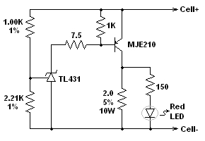
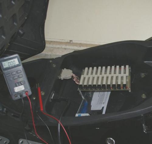
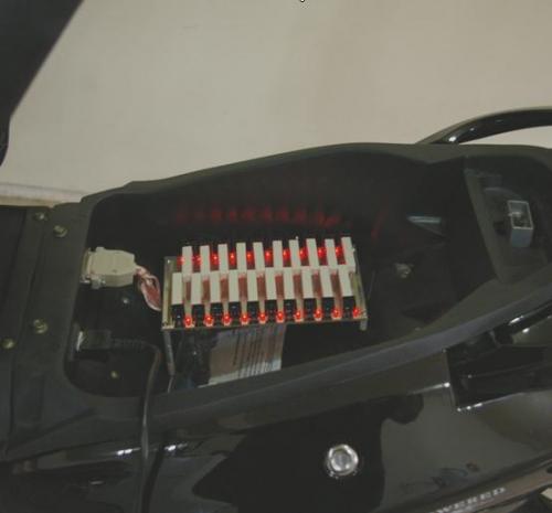
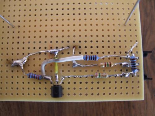
Below is schematic per cell, a Digikey parts list, and picture of it installed. The last picture shows it is balanced at the end of the full-current charge (it is shunting part of the full charger so the cell string still climbs to the shut-off point of the charger which is about 2 minutes when all LEDS are lit). It shunts the trickle current quite well and keeps cells balanced.
DIGIKEY PNS
A32508-ND CONN D-SUB RCPT 25POS AU FLASH
A32505-ND CONN D-SUB PLUG 25POS GOLD FLASH
V1034-ND PC BOARD PAD-PER-HOLE 4.5X8.08
MJE210GOS-ND TRANS PWR PNP 5A 25V TO225AA
TL431ACLPRAGOSCT-ND IC REFERENCE PROG 2.5V TO92
1.00KXBK-ND RES 1.00K OHM 1/4W 1% METAL FILM
2.21KXBK-ND RES 2.21K OHM 1/4W 1% METAL FILM
7.5QBK-ND RES 7.5 OHM 1/4W 5% CARBON FILM
150QBK-ND RES 150 OHM 1/4W 5% CARBON FILM
CPRB-2.0-ND RES 2.0 OHM 5% 10W WIREWOUND AXL
HS121-ND HEATSINK TO-220 5W BLK


Correction above; for the BMS balanced battery worse case voltages of 3.602 and 3.643, this is a +/-0.020V difference, NOT 0.2!
Green electric power and use thereof; what more do we need?
Seems that you could design that as a per-cell module that is bolted directly to the battery terminals. I've held such a module in my hand.. FWIW
It looks like this does not do low voltage cutoff. Instead only that it shunts power from the charger if the voltage is too high.
- David Herron, The Long Tail Pipe, davidherron.com, 7gen.com, What is Reiki
Hi David - totally agree; having this as a module next to the battery would be the ultimate (I built it this way for debugging and for accessing the cell voltages for development).
I also did not add the LVC since I am going to use a Paktrakr to measure cell voltages and it has an LVC alert. In the long run one would definitely want to add the LVC (easily done with an additional TL431 for indication but you would have to use opto's to combine them all if you wanted a control signal for controlling the bike's electronics - this type of circuit has already been built and available as someone pointed out in another thread but it is lower current).
I built this one as I wanted to make sure my cells remain good before I started using the 3500 a lot with some form of chrage balance and I wanted a 1.5A shunt capability to work with the thundersky charger. Plus it was a fun project (yes, I need to get a life as my wife says!)
Green electric power and use thereof; what more do we need?
I didn't layout an actual PCB for this but used a perf board. Here is a sketch on how to hook it up. If I build any actual boards, it would probably be the per battery module that would mount right next to the battery.
Also, as an FYI - the heatsink called out in Digikey is for a TO220 so has to have its retainer clips bent to work with the TO225 of the MJE210. If you consider using a different PNP transistor be aware as this circuit is designed around the saturation characteristics of the MJE210. Same goes for the TL431 since the one I chose can have 150mA.
Green electric power and use thereof; what more do we need?
Nice simple design!
Putting it on a PC board that fits on the top of a Thundersky cell would be just the trick. Others have done this, but they are PIC based designs with way too many bells and whistles for me.
I just finished putting together a Gary Goodrum/Richrd Fetcher board as discussed here:
http://www.ssec.wisc.edu/data/east/latest_eastvis.gif
Being designed mostly with e-bikes in mind, their shunt driver transistor is s bit small. Also, the philosophy at endless sphere is that the charger current needs to be "throttled back" using a regulator circuit to allow proper balancing and/or to keep the shunts reasonably sized and to manage the heat. But then again, they are dealing with battery packs in closed bicycle pannier bags.
I'll report on their BMS when everything is in and running.
I suspect a satellite picture of a hurricane in the gulf of mexico may not have been the link you meant to post ;-)
- David Herron, The Long Tail Pipe, davidherron.com, 7gen.com, What is Reiki
:) EPEN , that looks as it will work . I think i used the same connector for my patch board 25 pin ? Like on the back of old computors ! Would you make one up for a friend that doesn't have the skills ?? could you at least draw up a PCB tracing path so we can copy it and cut our own board and TRY to make our own ??? Can I put this in the 3500LI manual ?? LaTeR
thank GOD I wake up above ground !!!!
Hi strawhistle - the sketch above is a pcb tracing path (single sided traces only). I would like to make a PCB module eventually for this that can go right at the battery (and probably put a 5A fuse just to be safe).
And yes, put it in the manual (PLEASE make sure to put a disclaimer as this is pretty new and power electronics always seem to end up needing some refinement - I didn't want to post this until I had worked with it for awhile and I still plan to watch things closely until I build some confidence and place it down permanently next to the battery). I wanted to post to get feedback and see if any other "brave" soles were willing to try it. ;)
P.S. Yes, this is your ol' parallel printer connector. One thing I have found is there is a good drop on the wires from the battery to the connector and then to the BMS (I used 22AWG wires) and I think the BMS circuit will work even better down by the battery.
Green electric power and use thereof; what more do we need?
;) EPED , Ya I used a length of Gen Cable 25PR 24 Ga. and tied the pairs togather that is rated about the same sa 20 ga. I cut them all the same length and used old telephone code to make 25 conductor cable with 1/4" spades and a 1/4" thick board with 25 5/8" wafer head screws to make 25 pointed contacts for aligater clips I got the cells balanced by charging the low ones and draining the high ones with a 10 W resistor the byke is holding even charge for now but i want to fix this as soon as posible, so if you make another perf board one , or don't need the one you have built !! I could use it ! I will see if i can use your printing to make some small boards thanks agin for all your work LaTeR
thank GOD I wake up above ground !!!!
Hey, take a look at this:-
http://tech.ph.groups.yahoo.com/group/ThunderSky/photos/browse/4fd8
http://tech.groups.yahoo.com/group/ThunderSky/message/1846
- David Herron, The Long Tail Pipe, davidherron.com, 7gen.com, What is Reiki
Nice work! I'm glad these people in a pinch are getting some solutions. Make sure you have redundancy incorporated, especially in this automotive project. I was going to build this circuit for everyone but realized with no redundancy they're better off with nothing. If it's stuck in the on position it will drain the battery until it's dead. If it's stuck in the off position, you're likely to never know until its too late.
Using a current bypass technique that balances the cells during charging and discharging, and doesn't waste energy as heat is another desirable feature, but in practice making it all work right is proving to be a much greater challenge. I go to bed working on it, I wake up working on it, I think about it with all my free time, and this has gone on for months! :-) It's an addictive hobby.
Did you see the TI BQ6400, it looks like it does EVERYTHING! Even bypass current up to 1A. It should be on the market by next scooter season.
XM-3000...
-DC-DC converter replaced with a Dell D220P-01 power supply.
-72V mod
-Expensive bank charger until I come up with something better... Still trying.
-
sparc5 - this is exactly why I only plug this in when charging! I need to see how it goes in the long run before I have enough confidence to put this down by the battery "permenantly"! ;)
Green electric power and use thereof; what more do we need?
oops,
Wrong link, from different correspondence. I'm sure everyone knows where the ES forum is anyway.
But if I may ask again - has heat been a problem so far with this BMS?
Hey PJD - thanks for the feedback. It does get warm at the end of the charge cycle but usually is only kicking in for the last minute. It does not appear to be an issue so far.
However, mounting this next to the battery will require some thought as far as heat.
Green electric power and use thereof; what more do we need?
Does anyone know if the manufacturer is going to provide the BMS?
I am attempting to make the XM-3500 BMS Circuit and I could not locate the Digi Key part number for the LED. Will any 5 volt LED work?
Sorry about that. I had LEDs laying around so didn't buy any. You need one with a forward drop of about 1.6-1.8V at ~6-8mA. A good, low priced one from digikey is 754-1245-ND.
Green electric power and use thereof; what more do we need?
Thanks for the LED part number. I now have all of the parts to start putting it together. I am having some difficulty figuring out component placement. Do you have a picture (top and bottom) of one of the 20 units that I could use as a template?
Here´s a couple of pictures of mine, Eped have propably placed them smarter.
I´m just a simple amateur with very limited experience in electronics... :-)
http://www.postimage.org/image.php?v=gx1GSaRi
http://www.postimage.org/image.php?v=Pq1WekGr
http://www.postimage.org/image.php?v=aV1VQqX9
Good luck!
Johnny
Thanks Johnny! These are better then mine (I had reworked mine a few times before I got the final design so yours look nicer!) :)
Green electric power and use thereof; what more do we need?
Thank YOU!
It´s working better and better just as you said, now it´s only 2 LEDs not on when the charger stops.
I have to admit that it took me several hours to solder all the circuits and cables.
Here´s another pic, overview: http://www.postimage.org/image.php?v=gx1Hl449
Johnny
Excellent! This is good news.
Just a quick note - eventually all the LEDs should light up before the charger shuts off, but the last couple may be dim. This is fine as the cells will still all be very close (it all depends on the tolerance of the charger and where it shuts off - you may even have the charger such that you get all on nice and bright which is fine also). Another thing is spot check your cell voltages as even if one is not lit it may just be right on the edge but the cells will all be good. Send some voltages if you get a chance! ;)
Green electric power and use thereof; what more do we need?
The first one is assembled. At what voltage should the LED be on? The reading on the battery is 4.0 volts and the LED is not on. I put 2.5 volts (two almost depleted AA batteries) on the LED and 150 ohm resistor and the LED was on. I wanted to check the first one before I proceeded to the rest to ensure I put each together properly.
It should come on about 3.62V give or take. Can you send a picture of the bottom and top?
Green electric power and use thereof; what more do we need?
Here are the pictures. I did rough soldering to check out the circuit.
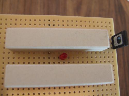
top
bottom
Thanks for your help.
It looks correct. Please make sure the battery is hooked up as shown in the picture below. Also, let me know the value of the one circled resistor and also measure the voltage at the one point when the battery is hooked up. Thanks
Green electric power and use thereof; what more do we need?
Sorry, I should have left the red/black jumpers on the connections to take the pictures. Anyway the resistor measures 2.20k (The colors are Red, Red, Brown, Brown, Brown) The voltage is 2.49. The battery voltage is 3.64.
The battery being 3.64V and the point you measured at 2.49 are correct. Measure the one end of the 2ohm resistor not tied to the battery negative (or see if the resistor is warm). The battery at 3.64 is about where the BMS turns on. Is the LED light on at all (even barely)? Was this battery 4V before you hooked it up (it is possible the main circuit works and the LED is not hooked right so the BMS brought the battery to 3.64V).
Green electric power and use thereof; what more do we need?
When you tested the LED, did you do it in this circuit and did you put the positive in on the 150ohm resistor side with the negative where the battery negative hooks up?
Green electric power and use thereof; what more do we need?
I think I understand now. The actual voltage was never above 3.6, only the no load voltage was 4.0. As an experiment I used a four "D" cell flashlight (with weak batteries.) The no load voltage was 5.8, when I attached the bulb from the flashlight the voltage dropped to 5.1. When I attached the BMS the voltage dropped to 4.0 and the LED was on. Sorry for the confusion, and thanks for checking my work and helping me diagnose the problem. I'm glad you are willing to be very helpful. Now to do the others.
Pages