GreenBMS V3

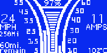
Main Screen Style A
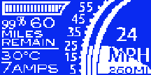
Main Screen Style B
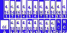
Cell Voltages
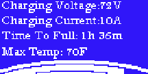
Charging
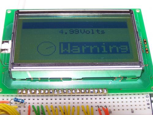
Here are some screens I was trying out on the 128x64 3" LCD. I know it doesn't look like it, but each one took almost an hour to make. I tried two versions of the main screen. Here are some of the kinds of things you can adjust or display and record on an SD card.
0x01 R/W RemainingCapacityAlarm unsigned int 2 0 65535 — mAh or 10mWh
0x02 R/W RemainingTimeAlarm unsigned int 2 0 65535 — min
0x03 R/W BatteryMode hex 2 0x0000 0xffff —
0x05 R AtRateTimeToFull unsigned int 2 0 65535 — min
0x06 R AtRateTimeToEmpty unsigned int 2 0 65535 — min
0x08 R Temperature unsigned int 2 0 65535 — 0.1°K
0x09 R Voltage unsigned int 2 0 20000 — mV
0x0a R Current signed int 2 –32768 32767 — mA
0x0b R AverageCurrent signed int 2 –32768 32767 — mA
0x0c R MaxError unsigned int 1 0 100 — %
0x0d R RelativeStateOfCharge unsigned int 1 0 100 — %
0x0e R AbsoluteStateOfCharge unsigned int 1 0 100 — %
0x0f R/W RemainingCapacity unsigned int 2 0 65535 — mAh or 10mWh
0x10 R FullChargeCapacity unsigned int 2 0 65535 — mAh or 10mWh
0x11 R RunTimeToEmpty unsigned int 2 0 65535 — min
0x12 R AverageTimeToEmpty unsigned int 2 0 65535 — min
0x13 R AverageTimeToFull unsigned int 2 0 65535 — min
0x14 R ChargingCurrent unsigned int 2 0 65535 — mA
0x15 R ChargingVoltage unsigned int 2 0 65535 — mV
0x16 R BatteryStatus unsigned int 2 0x0000 0xffff —
0x17 R/W CycleCount unsigned int 2 0 65535 —
0x18 R/W DesignCapacity unsigned int 2 0 65535 — mAh or 10mWh
0x19 R/W DesignVoltage unsigned int 2 7000 16000 14400 mV
0x3c R CellVoltage24 unsigned int 2 0 65535 — mV
0x3d R CellVoltage23 unsigned int 2 0 65535 — mV
0x3e R CellVoltage22 unsigned int 2 0 65535 — mV
0x3f R CellVoltage21 unsigned int 2 0 65535 — mV
0x3c R CellVoltage20 unsigned int 2 0 65535 — mV
0x3d R CellVoltage19 unsigned int 2 0 65535 — mV
0x3e R CellVoltage18 unsigned int 2 0 65535 — mV
0x3f R CellVoltage17 unsigned int 2 0 65535 — mV
0x3c R CellVoltage16 unsigned int 2 0 65535 — mV
0x3d R CellVoltage15 unsigned int 2 0 65535 — mV
0x3e R CellVoltage14 unsigned int 2 0 65535 — mV
0x3f R CellVoltage13 unsigned int 2 0 65535 — mV
0x3c R CellVoltage12 unsigned int 2 0 65535 — mV
0x3d R CellVoltage11 unsigned int 2 0 65535 — mV
0x3e R CellVoltage10 unsigned int 2 0 65535 — mV
0x3f R CellVoltage9 unsigned int 2 0 65535 — mV
0x3c R CellVoltage8 unsigned int 2 0 65535 — mV
0x3d R CellVoltage7 unsigned int 2 0 65535 — mV
0x3e R CellVoltage6 unsigned int 2 0 65535 — mV
0x3f R CellVoltage5 unsigned int 2 0 65535 — mV
0x3c R CellVoltage4 unsigned int 2 0 65535 — mV
0x3d R CellVoltage3 unsigned int 2 0 65535 — mV
0x3e R CellVoltage2 unsigned int 2 0 65535 — mV
0x3f R CellVoltage1 unsigned int 2 0 65535 — mV
0x4f R StateOfHealth unsigned int 1 0 100 — %
0x51 R SafetyStatus hex 2 0x0000 0xffff —
0x53 R PFStatus hex 2 0x0000 0xffff —
0x54 R OperationStatus hex 2 0x0000 0xffff —
0x55 R ChargingStatus hex 2 0x0000 0xffff —
0x57 R ResetData hex 2 0x0000 0xffff —
0x5a R PackVoltage unsigned int 2 0 65535 — mV
0x5d R AverageVoltage unsigned int 2 0 65535 — mV
Questions:
How much room do I have to work with in there? height of a thundersky cell turned on its side
Can you turn on a small TV tune it to a high frequency, put it close to the scooter, and run the motor?
Wire Guage: 8
The length of the longest wire: ?
- sparc5's blog
- Log in or register to post comments

Who's online
There are currently 0 users online.
Who's new
- eric01
- Norberto
- sarim
- Edd
- OlaOst
Support V is for Voltage

Comments
Re: GreenBMS V3
The 40ah Thundersky: Dimension: 190X116X46 mm or 7.48X4.57X1.81 in
The 60ah Thundersky: Dimension: 215X115X61 mm or 8.46X4.53X2.40 in
(source)
I think the XM3500 uses the 40ah battery, and the EVD uses the 60ah one.
I like the displays. You don't have many pixels to work with, so it's not going to be real pretty, but they look usable. I'd suggest you stay away from curved lines if possible, they are going to look pretty jagged.
My electric vehicle: CuMoCo C130 scooter.
Re: GreenBMS V3
You da man sparc.
I completely believe it took at least an hour per screen.
You musta locked yourself in the EV cave today!
Just curious, the SOC meter, top center; is that Kwh based or pack voltage or?
So is there to be a CAL mode? do you fully charge, set 100% point, ride until voltage drop quickens, then set 0% point? then it just works? Maybe when you get down to 10% it starts blinking?
I think I like style A best(I know, you didn't ask:)
Say, what's the 250mi figure; odo?
Ogg loves the miles to go feature; essential; Ogg no like walk home unexpectedly.
Looks nice man,
Ogg
Re: GreenBMS V3
Ogg- Thank you for the kind words. The SOC meter gets its value from a fancy algorithm combining impedance measuring with a coulomb counter. The result is a 99% accurate SOC meter, that doesn't require the batteries to be drained once to be calibrated, and adjusts for temperature and age effects. They will auto-calibrate. The miles remain feature is limited to at current energy discharge rate. If the last part of your trip is up a mountain, you'll see the miles remain change to reflect new discharge rate.
The 250mi is the odo! You know you want it ;-)
I've hired a guy to help me move this project along more quickly. He's a talented freelancer who is quite enthusiastic about the open source project and cause.
Today the GreenBMS screen went through rigorous environmental tests. Placed in a bucket of acid, 3.5G shock test, put in the toaster, put in the freezer. Next up is UV exposure, and sunlight readability.
I don't have an XM-3500li, or any lithium scooter so I need to know the following things:
1) What is the length of the longest battery wire:
2) If you tune a TV to a high channel, and run the motor near it, is there any interference?
3) Is there a place to mount this BMS that can withstand a lot of heat?
4) Can someone put a scope on a hall sensor and upload the image?
5) For those without a scope, and maybe just a multimeter, how many degrees can you turn the wheel to complete one on off cycle / how many times does the sensor output go high and low in one revolution of the wheel.
Here is some more BMS p0rn:
The circles don't look half bad after all MikeB. Thank you for the info, it's just what I needed.
XM-3000...
-DC-DC converter replaced with a Dell D220P-01 power supply.
-72V mod
-Expensive bank charger until I come up with something better... Still trying.
-
Re: GreenBMS V3
Hmm,
OK, yeah, Ogg Dodo, Ogg want ODO!
Here Goes:
1) What is the length of the longest battery wire:
I'm not sure if you're after back of pack to dash, or front of pack back to last cell? So I'll describe it a couple ways:
Back of pack forward Horizontally to steering yoke=32"; From there, vertically to top of yoke =21".
Total Pack length=24"
And, front most cell Horizonatally back to area beneath seat=24", and from there, Vertically to TOP of under-seat compartment(center)=10"
2) If you tune a TV to a high channel, and run the motor near it, is there any interference?
Sorry, can't get the bike into the living room, or the TV out to the garage :)
3) Is there a place to mount this BMS that can withstand a lot of heat?
Do you mean the display? The balancing circuitry?
There's an 8x8x7(LWH) "chamber" below the front of seat, in front of the underseat storage, above the cells and that area has some passive venting low in front and on the sides. A board(s) could be mounted in there. It would obscure the cell-tops, but that's OK and I suppose the board could be hinged(nah, prolly a bad idea!). Note that this is all covered by the molded plastic cover which is screwed on; so not easy access(Seat has to come off first).
I'm figuring I'll sacrifice my underseat storage for a BMS, though there's currently no venting there; but the "chamber" seems ideal.
4) Can someone put a scope on a hall sensor and upload the image?
Not until I get my replacement cell and drive it to work; cell due this week.
You're on the Peninsula, right? I could shuttle it down if that'd be easier and/or useful. I've got a rack on the van for it; pretty easy on/off. I'll PM ya.
5) For those without a scope, and maybe just a multimeter, how many degrees can you turn the wheel to complete one on off cycle / how many times does the sensor output go high and low in one revolution of the wheel.
Can try soon, but my batt's are disconnected awaiting the replacement and my Ammeter/Shunt Install.
Re: GreenBMS V3
From peeking in the vent holes on my EVD, I think that 'chamber' is occupied with more batteries on my bike. There might be room for a circuit board still, I'll do some investigation this weekend. What type of size are you looking at?
For both the EVD and the XM3500, I think there is a great place for the display to be embedded in the plastic that covers the handlebars. You might have to cut out a rectangular opening in the plastic, but it looks like there is room inside. Of course, if the display is thin enough, it could just be attached to the surface.
My electric vehicle: CuMoCo C130 scooter.
Re: GreenBMS V3
Thank you Ross and Mike B!!! Your help is invaluable. How many amps does it use when motor is at full throttle? XM-3500 is 80A if I'm not mistaken. I don't know about EVD.
I was talking about the BMS w/o display, Since I have no EVD or 3500 I am trying to learn from all of you how much room I have to work with. If it's anything like the XM-3000 the scooter has a plastic floor, with a few perforated rectangles that can be cut out. Preferably it would be placed in a location that wouldn't come in contact (thus heat) the cells.
I got to thinking about the display yesterday. Experimenting shows it needs to be protected from water and allowed to vent heat. Condensation is the other design consideration. I could put it in an enclosure like the PakTrakr is, or I could embed it in the handlebars, a more elegant solution, but need to know how to go about it.
XM-3000...
-DC-DC converter replaced with a Dell D220P-01 power supply.
-72V mod
-Expensive bank charger until I come up with something better... Still trying.
-
Re: GreenBMS V3
It's here!! Soldering is gonna be a new issue.
XM-3000...
-DC-DC converter replaced with a Dell D220P-01 power supply.
-72V mod
-Expensive bank charger until I come up with something better... Still trying.
-
Re: GreenBMS V3
Soldering the chip onto a expander for breadboard testing using a laser and pneumatic solder paste injector. It took my engineer Claude 2 hours to solder just those 10!!!
XM-3000...
-DC-DC converter replaced with a Dell D220P-01 power supply.
-72V mod
-Expensive bank charger until I come up with something better... Still trying.
-
Re: GreenBMS V3
Sparc,
Is this your setup? pretty slick.
I've only used the toaster-oven & solder-paste method for surface mount soldering. I can't see those small leads anymore anyway.
Wow, that's exciting you've got that chip to play around with, whoo hoo.
XM-3500Li Current Limit:
Yes, Mountain posted that the 3500 is limited at 80A.
Back to the on-bike PCB space:
I think a board could mount vertically within the sub-frame on which the seat mounts and the front of the under-seat tub mounts.
This is just behind the aforementioned "chamber".
The space within the sub-frame is 5"H x 9"W max.
And, on the 3500 there's a 4"x5" "access-panel"(3 screws) on the front of the under-seat tub which might be useful for occasional access to that space.
I'll get some photos and add them here later.
The charge connector would need to be moved as it juts into this space; no big deal though.
Display Mount:
Yeah, there's a roughly 3"x1/14" flat-ish spot on top of the handlebar cover; though then you've got the flex-stress on any cable going to it.
I'd probably mount on the left-side dash blank on the 3500; I know the Efun uses that space though. I guess flexibility is in order...for placement and cabling.
Re: GreenBMS V3
I'm with you ross.
Just took this image on my EVD, looking under the seat with two panels removed:
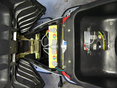
As you can see, I've got a cluster of batteries between the seat hinge and the underseat box. It's hard to judge the depth in this photo, but there is a little bit of space in front of those batteries, beneath the seat hinge and supporting structure. The small access panel under the seat also reveals some space beneath the underseat, behind those batteries. The forward location has the advantage that the charging cable goes out through the locking gas panel in the middle of the scooter floor, so we could put in a 2nd charging plug for the BMS there.
Btw, the full set of pics for my bike is at http://picasaweb.google.com/mikeboni/RMartinEVDLFP#
My electric vehicle: CuMoCo C130 scooter.
Re: GreenBMS V3
Man, that thing is OVERFLOWING with Lithium!
How are the cells arranged in it?
3 across x 6 below, then three up top? 5 up top?
How can you not have cells below your fuel door? Where the heck are they all?
Or is there a black separator down in there, on top of the cells?
Oh, I wanted to ask you; tell us about the gauges on the dash; How are they set up?
How're you liking the scoot?
Ross
Re: GreenBMS V3
So it looks like the ideal spot is near the seat hinge?
Tips of magnet wires enamel stripped off with acid, all 48 pins connected and tested for continuity.
Encased a coat of epoxy. Beautiful work by Claude.
XM-3000...
-DC-DC converter replaced with a Dell D220P-01 power supply.
-72V mod
-Expensive bank charger until I come up with something better... Still trying.
-
Re: GreenBMS V3
I'll remove some more panels this weekend, to figure out the full battery arrangement.
I think there are cells below the fuel door, but there is a black separator on top of them, so the charging plug sits only an inch or two below the door.
Dash: volt meter on right, speedo/odometer in center, clock bottom center, diagnostic LEDs on right side. If I had to cover something, the diagnostic LEDs would be the first to go, though the BMS display would probably make the volt meter redundant, so it could be covered instead.
I'm liking it so far, though dropping from 50hp in my gas scooter to 4hp in the EVD makes it feel underpowered. I'll probably get over that feeling eventually, I think the EVD really does have enough power for the slower roads (and my Silverwing has more than I need most of time).
sparc5: yea, from what I can tell, the seat hinge is on top of an upside down U shaped piece of tubular frame. My choice, if it fits, would be to place the BMS board(s) vertically within that U. There is a bit of air space all around, and some vents to the side, but the space is pretty well protected otherwise. And a couple of clamps around the tubing would make a solid mount point.
My electric vehicle: CuMoCo C130 scooter.
Re: GreenBMS V3
Ok, got some panels off and some pictures taken.
The battery layout on the EVD is 2x3 forward, 3x3 aft, and 3x2 up top, 21 total.
I'd say the space below the seat hinge would be a reasonable mounting location for a BMS board, I'd say 7' tall, no more than 5 1/4" wide at the top, and at least 4-5" deep.
Click for image.
Of course, getting into that location for mounting takes some work removing body panels, but once installed it should be mostly hands-off (hopefully). You can easily run cables forward from there for a charging plug and display unit, and it's a pretty central location for connecting to all the batteries.
My electric vehicle: CuMoCo C130 scooter.
Re: GreenBMS V3
Mike B,
You da man!!! Thanks for the great view of the space I have to work in. It's exactly what I needed.
Today's progress went into building a web site, writing the code for he LCD, and building a mock up wheel with a hall sensor.
XM-3000...
-DC-DC converter replaced with a Dell D220P-01 power supply.
-72V mod
-Expensive bank charger until I come up with something better... Still trying.
-
Re: GreenBMS V3
Sparc,
I purchased a outdoor rated electrical timer this weekend, so I can charge my bike up overnight. However, as I got on the bike this morning, my first thought was 'did it actually charge?' (I don't really trust the onboard voltmeter much) I'm considering buying a Kill-a-Watt so I can confirm that 'x' kWh of power flowed through the charger overnight, which would provide a reasonable confirmation that the batteries were charged.
I'd like to suggest that you build such a display into your screens. If I do lots of riding one day, and expect 3kWh of power in a recharge, but only see 0.1kWh overnight, I can quickly figure out that charging was halted/interrupted or something.
My electric vehicle: CuMoCo C130 scooter.
Re: GreenBMS V3
The Kill-a-Watt is a very nice thing to have, and not expensive.
I know you requested a charge timer before, that will be included. Funny I was just thinking about it this morning. I haven't seen any power meters yet that record when the electricity is used. You have one of these? It must be digital?
The BMS must monitor energy in and out, so displaying it is something I intend to do as well.
XM-3000...
-DC-DC converter replaced with a Dell D220P-01 power supply.
-72V mod
-Expensive bank charger until I come up with something better... Still trying.
-
Re: GreenBMS V3
The timer I have is nothing but a clock driven on/off switch, and I figured I'd just reset the Kill-a-Watt whenever I plug in at night.
Good to hear about the display. I'll keep throwing out ideas as they come to me. Btw, is your new web site visible to the world yet?
My electric vehicle: CuMoCo C130 scooter.
Re: GreenBMS V3
www.greenbms.com - who would have guessed?
It's not ready for prime time yet. I want to keep the focus the V blog until the product is ready for the public.
XM-3000...
-DC-DC converter replaced with a Dell D220P-01 power supply.
-72V mod
-Expensive bank charger until I come up with something better... Still trying.
-
Re: GreenBMS V3
I haven't posted in a while, I've been waiting for parts from Thailand to come. That chip adapter took too long to make. Luckily some guy in Thailand is making adapters, they came yesterday.
Waterproofing is a serious issue with this project. I don't have the tools to build custom cases, and I don't know where you can find an economical waterproof project box that has a directional button pad. So what to do? How about put the buttons behind the display glass!
Freescale is selling the chip to do it for $1.50, which is around what eight mechanical buttons would cost. It communicates via I2C. The cool thing is you print the button pads directly onto the circuit board. They are more like proximity sensors that detect how close your finger is to the pad. To prototype it though, circuit boards must be made. It is a new pain in the you know what...
I think I'll buy a CNC mill. This will also lower the time it takes to make the circuit boards. I've tried the old laser toner transfer method, it stinks for surface mount parts. There is a photo transfer method too, maybe it will work better but it's not as cool, and in the long run more expensive. The CNC mill can also make cases out of blocks of plastic. Before it comes all of the GreenBMS' systems can be built and tested except for the buttons. Expect more frequent progress reports in the coming days.
I also uploaded the videos of the LCD testing to the GreenBMS site.
XM-3000...
-DC-DC converter replaced with a Dell D220P-01 power supply.
-72V mod
-Expensive bank charger until I come up with something better... Still trying.
-
Re: GreenBMS V3
Think it's about time for a status update.
Progress continues every day. It's clear now why there is no BMS professional or hobby that has the same features of the GreenBMS. It's a hundred projects in one, more complex than anything else inside the scooter, and that's the slimmed version of the original!
As usual nothing goes simply. The Texas Instruments decided to create their own modified version of the standard communications protocol that chips use to talk to each other. Nasty surprise for interfacing this chip.
That's the bad news, the good news is we discovered it has a pre-charge feature which slows the initial rate of charging if your batteries are very run down, this is useful for keeping your batteries in good shape for a long time.
Anyways the CNC machine came. I can now build my own cases, circuit boards, and various Christmas presents for everyone in the family, metal fish skeleton anyone? I haven't had time to power it up yet, learning to run it is a whole new art form. It's like manually telling your printer how to draw pictures but in 3D, being mindful of limitations like depth and speed. It's made out of HDPE, which is the same stuff as plastic kitchen chopping boards.
Claude and I have been going over technical design choices. To our delight it won't be so hard to make it modular after all. We can set each slave address with tiny switches, giving us up to 255 slaves. Each slave capable of protecting up to 10 batteries. That should give us access to the EV market, but we'll need to have a beefier components to power 255 slaves. There will be a master rack, and you can stack three slaves side by side on top of it, it is held together with two strong bolts.
Claude finished the circuit layouts. It's a work of art. It takes several huge breadboards to fit it all, he's working on it as I type.
Last night I decided GreenBMS is a nice product name, but I need a company name. How does Petrol Avengers sound? The logo will be an oil drop with the crossed circle around it, but the cross will be a lightning bolt. I like it, but Claude said he'll burn the shirt if if I ever send him something like that. Anyone have a better idea?
XM-3000...
-DC-DC converter replaced with a Dell D220P-01 power supply.
-72V mod
-Expensive bank charger until I come up with something better... Still trying.
-
GreenBMS V4
Hi Scooting type people,
Sorry for the long space with no news. I've slowed the pace of development since in the winter not so many people are out scooting around, not to mention there is a working BMS plan on another thread for the people who can't wait.
As you saw in the last photo I got a CNC machine. Using it isn't as easy as going to file->print. It took a lonnnng time to learn how to use. The software manual is 500 pages long! So now I know how to make things in cad, and make it a physical reality! This speeds the development of the circuit boards, and might also be a good way to make cases for the BMS in medium sized quantities.
As is always the case with technology, the longer you wait, the better the stuff is..
Texas Instruments came out with a new chip, one that does everything. It balances batteries by shuttling the charge from stronger cells to weaker ones giving you more range on your rides. This is a vast improvement from the standard method of no discharge balancing, and charge balancing by burning off excess current as heat. I wanted to do this always, but patent issues got in the way. Now TI has saved us.
The other big bonus of the new chip is that it accurately measures battery charge to 99% accuracy, no calibrating discharge needed, no adjustments for aging batteries' personalities. It's so accurate it is approved for use in medical equipment!
I'll try to be finished by the time scooter season starts back up.
XM-3000...
-DC-DC converter replaced with a Dell D220P-01 power supply.
-72V mod
-Expensive bank charger until I come up with something better... Still trying.
-
Re: GreenBMS V4
Oooh.. that sounds exciting. And I have been wondering about your absence, glad to hear you're doing productive learning.
- David Herron, The Long Tail Pipe, davidherron.com, 7gen.com, What is Reiki
Re: GreenBMS V4
Hey Sparky-- I was just going to delete this page from my Bookmarked section and you show up! BRAVO on the work you are doing. I am excited
to see the completion of your project as I hope to be one of your first customers. I do not have the EE brain to do all of the putting together of kits that the other guys are doing. I would much rather buy it off the shelf and I do certainly trust your knowledge.
My XM6000 should be getting out of the shop any day now (this is mechanic speak that they do not know when it will be done) and since I will be running 24 cells and a 6000watt 72 volt system I will be anxious to get a BMS on it asap. I know we have a 2 year warranty on our batteries but still I would rather do it right from the get go and not have to replace unbalanced batteries every couple of months.
Please keep up the good work and let me personally know when you need a guinea pig or are ready to go. Best....Mikie
mikie
Re: GreenBMS V4
Good idea.
This graphic is free to use.

Re: GreenBMS V4
Hey Sparc,
Thanks for the update! that's really cool news on the GreenBMS.
Does this mean you're switching designs to the new TI chip?
I'm down for some multiples when you get 'em together, whatever they are.
Where'd you get the CNC device? that sounds like fun.
I want to make some cases for my blue LCD Amp and Pack Volt-Meters.
Are they really $$$$; have a link?
Glad we didn't lose you to the Chicago snowdrifts.
cheers,
Ross