So far I have added:
1. Cell Monitoring wires from each cell (with X-Treme's permission) ending in a 24-pin connector to facilitate measuring all the cell voltages.
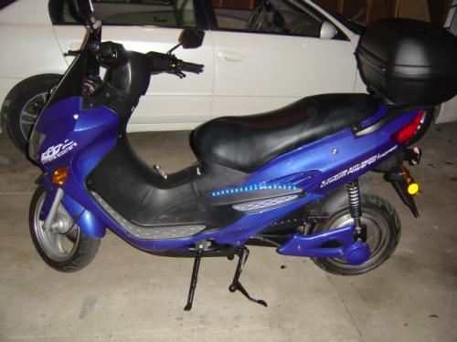
2. A locking Trunk (SHAD "50") mounted on the rear "rack".
3. A custom-designed Battery Fuse and Interconnect card has been built, to be installed as soon as I can "mount" it safely. It holds a fuse for each cell and provides a standard "power jack" for each cell to allow convenient use of a simple voltmeter to quickly measure the cell voltages.
I will post pictures and more details of each item soon.
Items #1 and #3 form the basis for a "poor-man's" BMS (Battery Monitoring System). With some thought, #3 could be used as a "manual" cell balancing system.
To maintain the Battery Warranty, the battery should only be charged with the supplied TS "smart" Charger. It appears to do a good job if the Pack's cells are reasonably balanced.
However, measuring cell voltages (specially with any unusually low impedance "crude" voltmeter) would tend to drain some (usually very small) amount of charge from the cell being measured. If one finds a cell that has become charged too much, say over 3.7 (or so) volts, just leaving the "crude" voltmeter on that cell for a while would tend to discharge that cell a little bit.
Obviously, if one used this "crude" type of voltmeter, one would want to be careful to not "measure" any one cell too long. However, while just making measurements, one might observe a cell's voltage dropping a bit. If that happened to help balance an out-of-balance pack, then so much for the good.
At least one can occasionally check for the potentially harmful "out-of-balance" condition, and, after gathering some cell "history" data, possibly even detect a "weak" cell.
More later.

There might be those who would ask if it is possible to charge the too-low cells a bit, perhaps using the inexpensive 2-amp LiFePO4 single-cell charger available from the www.VoltPhreaks.com web site?
I would answer that it could be done, would probably be quite effective, and is unlikely to damage any cell because that charger is said to have a maximum voltage output of about 3.7 or 3.8 volts. However, the quality control and uniformity are unknown, and I do not personally know what would happen if one of those small, isolated-output chargers was connected to a cell that is already ABOVE its maximum charging voltage.
Also, its use is likely to void your two-year X-Treme Battery warranty, so I cannot recommend this excellent technique. Not only would using one charger void the warranty, but using 21 chargers at once might void the warranty 21 (or 21 factorial) times.
Those already past their warranty period, or those with special needs or circumstances will probably be drawn to try this anyway, and do so entirely at their own risk.
Cheers, Gary
XM-5000Li, wired for cell voltage measuring and logging.
Gary, have you looked at the Paktrakr? It's a battery monitoring system on steroids and it can handle LiFePO packs.
- David Herron, The Long Tail Pipe, davidherron.com, 7gen.com, What is Reiki
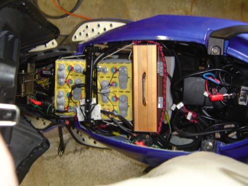
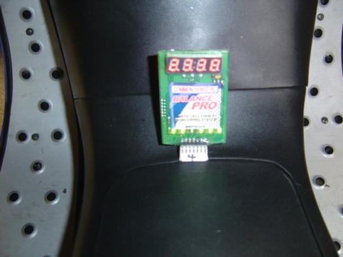
Gary, will you be selling the fused battery connect cards? That would be a nice addition to what I have done already. Here's a couple pictures of my 3500li mods. Notice 3 300amp battery iso switches to switch back and forth from 24 to 28 cells. The small black charger mounted towards the back with the clamp type charging leads is a 4cell lifepo4 charger the other is the TSL72-15. You'll notice four white connectors by the small charger. Those are four of my 5 battery monitoring connectors. I divided my pack into 5 sub packs. Four 6cell packs and one 4cell pack. This way I can use one of those battery monitor/balancer cards from commonsense RC to monitor and balance my cells. I ran one balance lead up to the (charging hatch?) so I can watch 6 cells in real time while driving.(see picture)But the pack tracker is definitely the hot setup. I put another picture of the regen brake setup I made in also. This works good because the way it;s set up you just work the brakes like normal only you lightly squeeze the handles then use the trigger to do the real braking. This way you are ready on the brakes if the trigger fails you. I don't know how others are setting these up but this seems to work great and have redundancy. I wish I had the 5000 kind of though as I would like the 60AH batts. Keep up the great work I look forward to hearing from all of you innovators out there. PS I also wanted to mention I did decide to mount my circuit breaker horizontal as hard bumps may make the contact chatter causing early failure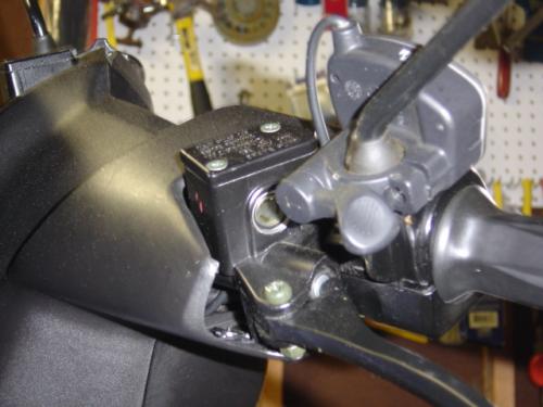
2008 XM3500li Mods/Kelly KBL12251/84v 28cell 40AH pack/ Variable regen brake trigger on left brake handle/Givi/Cycle Analyst/Homemade BMS
KMX Typhoon Home build (recumbent pedelec) with two Astro Brushless 3220motors/twin castle Phoenix ICEHV 160/ Cycl
The metal mounting "platform" for the SHAD Trunk is meant to be fastened to a flat rack. However, the rear rack of the XM-5000Li has a rounded top surface, and trying to fasten the mounting platform down to the rounded surface would bend the metal platform. So, I drilled 4 holes in the rack, and tapped the holes for the 6x1 mm bolts that were supplied with the trunk.
I put a washer on each allen cap bolt head, passed the bolts down through 2 enlarged and 2 new holes in the mounting platform, added a washer underneath, and finally added two "nylock" type nuts, tightened just enough so that the bolt head could still be turned with an allen wrench. I then drove the bolts down into the threaded holes until the nuts were snug against the rack, and the metal mounting platform was held securely in place. I then put the plastic quick-disconnect platform on the metal platform with the four included hex-head bolts.
Then, the trunk mounts nicely, as seen from the left side:
And, as seen from the rear:
The trunk has room for two full-face helmets and some small items, or my helmet, gloves, and riding jacket.
This trunk can be removed (using the key) from the plastic quick-release platform.
One review on the web describes this trunk as about 6 pounds empty, but it is more like 6 kg.
I have already used it on two trips, and it is a very nice, convenient trunk.
Cheers, Gary
XM-5000Li, wired for cell voltage measuring and logging.
Iccarus,
Yes, I will make the board available to others, perhaps offering one or more of these configurations:
1. a board and parts list,
2. a "kit" with the board and the on-board and the associated mating parts,
3. a completed board and the associated mating parts.
Probably AndyH will sell it through his dealer website, but prices and configuration(s) have yet to be set. If you have suggestions on configuration or pricing, feel free to let me know, either with a post here or via a PM. There are a few boards available, and several can be "completed" quickly.
Only 23 cells are supported through the 24-pin connectors, but the board allows an additional wire to be connected to support 24 cells. There are spaces on the board for 24 fuses and 24 "jacks".
Here is my board, completed for 21 cells, with 5-amp "automotive" fuses (that plug into "naked" spade lugs). It is 8.4 x 4.5 inches.
I intend it to be used as a convenient but inexpensive way to check and help maintain your battery's cells in good balance. Of course, one might want to be careful to use it in such a way as to maintain any existing warranty.
WARNING: Dangerous and powerful DC voltages are present, so the board needs to be mounted carefully to keep the back side from shorting against anything. Use at your own risk. I strongly recommend putting a fuse (maybe 10 or 20 amp) in each wire coming from a cell, right near the connection of the wire to the cell terminal.
With an inexpensive digital voltmeter (VOM) from somewhere like Harbor Freight, and a little "invention", one can actually manually maintain the battery Pack with this board.
The three center connecters allow one to attach other devices, like my PakTrakr. With it, and a program I wrote (PtViewer), I can log and view all the cell voltages, but that is an expensive addition that most will not want to be bothered with. I needed it to investigate how well the supplied ThunderSky "smart" Charger was able to do its job.
If you check your cells initially (and then occasionally) and balance the cells manually (when needed), the TS charger for the 5000Li seems to do a pretty good job of "red-light" mode charging (if you do not let the charger run in the "green-light" slow-charge mode for more than an hour or so). It appears to me that the charger can take some cells "too high" in the slow-charge mode, so I am not yet willing to let it run in that mode without a protective BMS "cell-shunt" circuit attached.
If one had such a BMS circuit, and chose to use it, this interconnect card provides a place to plug in the BMS while charging.
I will be making a Low-Voltage Cell-Monitor board next. I intend to watch two voltages, a higher cell voltage for a warning (maybe an LED) and a lower cell voltage that some might use for a warning alarm or to actually cut off the controller or motor.
Cheers, Gary
XM-5000Li, wired for cell voltage measuring and logging.
Gary,
I have an initial entry for the interconnect board in the store. Yes - they'll be priced a bit higher than $0.00. :-)
The rest of my parts should arrive on Monday; I'll finish my boards and get one in my 5000. I'm looking forward to clearing my wiring clutter and reclaiming the space used by my three fuse blocks. Thanks for the work you put into these boards - they came out great!
Andy
I got my Battery Interconnect Board installed in my 5000Li today.
I moved the circuit breaker from the front side of the "arch" to the rear side. I disconnected the breaker from the arch, turned the arch around, and reconnected the breaker, now on the rear side of the arch.
Then, there was enough room for a cut-down plastic tray to sit on top of the upper 6-pack, with the interconnect board laying in it.
Finally, I connected the 24-pin connector with the 22 wires from the 5000Li's 21 cells, and ...
nothing blew up! Cool.
Not really elegant, but functional.
I will post some pictures tomorrow.
Cheers, Gary
XM-5000Li, wired for cell voltage measuring and logging.
Here is a picture of my single charger connector board.
I wired cables from all the batteries to a VAL-U-LOCK connecter.
Then I used allready owned (experimantal with holes drilled) PCB and soldered connectors and cabels. I did not fuse anything!
Pictures of the spagetti wiring:
XM-5000li like scooter (top speed gps 938 Km/h max range (XM-5000Li speedometer) 87,6 )
Proempiet,
Welcome to the 5000Li Owner's Group.
It looks like you can now check your cell voltages easily.
I find it takes only about 60 seconds to check them all when I use a VOM with the "power-plug" modified test leads.
Harbor Freight stores have these VOMs on sale now for $2, down from $8 each.
I see somebody might have plugged in a single-cell "catch-up" charger ... in one of your pictures.
Is it the VoltPhreaks charger, or some other?
Thanks for sharing the pictures.
After riding 38 miles (two 19-mile legs, my first "long" ride) yesterday (with hills), I arrived back home with all the cells (at rest) at 3.18 to 3.20 volts.
However, under load, I had to go only about 20 mph on the flat to avoid the flashing red light, and could just "creep" up the last hill (approx. 6 blocks, 200 feet). Even though the "fuel" gauge got down to the "L" below the big red mark, and the red light was flashing wildly, it did carry me slowly up the hill. On the down-slope, it was "gutless", but wad trying to pretend that nothing was wrong!
So, I did make it home, even though I was worried that I would not make it! I do not think I could have pushed it up that last hill.
After charging with the standard TS charger, and letting the cells "rest" for 8 hours, I get 3.34 to 3.39 for most cells, and 3.40 and 3.42 for the two highest.
This "spread" of 3.34 to 3.42 is probably not very significant, but would seem to indicate that there is now a small spread in the State Of Charge (SOC).
I will watch to see what happens after the next ride and charge.
Cheers, Gary
XM-5000Li, wired for cell voltage measuring and logging.
Gary, I had to laugh about barely making it to your destination. It's happened to me many times as well. lithium batteries seem to hold a good charge right to the end then they drop off fast. I was riding around my neighborhood thinking I'll just stay close to my house but I was a little far away when my voltage on some cells were getting real close to lvc so I limped back and barely made it. I thought you would be getting better range. Maybe you pack is not fully broken in yet. What was your average speed. I'm getting 45 mi. or more at about 33mph on 24 40ah cells in my 3500. I even went 55mi keeping it economy mode the whole time. I haven't tested it since I switched to the Kelly controller w regen. My mileage figure is under optimum conditions. Flat open roads very little braking so the regen wouldn't mean anything on those figures. I hope you guys are having fun with your scooters because I love mine!
XM-3500Li,Kelly controller W/regen,24/28 cell capable,BMS
2008 XM3500li Mods/Kelly KBL12251/84v 28cell 40AH pack/ Variable regen brake trigger on left brake handle/Givi/Cycle Analyst/Homemade BMS
KMX Typhoon Home build (recumbent pedelec) with two Astro Brushless 3220motors/twin castle Phoenix ICEHV 160/ Cycl
Oh, yes, I am enjoying the riding. The 5000Li seems, so far, to be a well-built bike.
There were stretches of 45 mph, lots of stops, and some hills and long grades. The first 19 miles seemed to go well, but after a 5-hour layover and starting the journey home, the bike seemed that had lost some of its "get up and go".
This was my first more-nearly-discharged ride, and I have only 150 miles on the bike so far.
I am learning.
Cheers, Gary
XM-5000Li, wired for cell voltage measuring and logging.
I started by making a system cell-wiring harness in two main pieces:
1. Wires from 6 "cell-block" groups to 4 connectors.
2. A 4-to-1 "master" harness to bring all the 21 cells to one 24-pin connector.
The ends that will connect to the cells are color-coded, and get a 1/4 inch ring terminal crimped to the end. I should have added a fuse right at each cell.
These 6 groups ended in 4 connectors.
Then, the master harness has two ends, the one with 4 connectors, with wires color coded in 4-color cell order:
And the "user" end with the 24-pin connector (using 22 of 24 pins):
Then, the Block-Harness wires (now with no lose ends) are connected to the live cells. The other ends of the wires are safely in their connectors. Here we see the connections to three "blocks" of cells.
The 4 Block-Harness connectors are connected to the Master Harness.
Resulting in one "user-friendly" connector.
I checked that all the voltages in the Master Connector were as expected before I connected to anything else. I checked that all this wiring (better protected from chaffing by being enclosed in heat-shrink tubing) was well routed.
I was then ready to plug into to my Interconnect-Fuse-Monitor board.
Also, I occasionally connected a PakTrakr to monitor and record (and graph) the cell voltages before, during, and after I charged with the ThunderSky Charger.
Cheers, Gary
XM-5000Li, wired for cell voltage measuring and logging.
I wanted my Interconnect Board to be easily available when the seat was lifted, but not be in the Cargo Bin. I wanted to save the Cargo Bin for carrying the TS Charger and an extension cord.
So, that meant that the Interconnect Board needed to "live" just forward of the cargo space. I bought a plastic drawer-divider type tray (about 9 x 6 inches inside dimensions) from the housewares section at WalMart and cut the sides down to about 1" high. This tray has a light grey non-skid inner coating, and is a little thicker than the least expensive just-thinner-plastic trays. It could safely contain the Interconnect Board, and just fit ... if I moved the Circuit Breaker to the rear of the "arch".
In front of the arch, the Circuit Breaker is in the way:
Wanting to minimize modifications, I just disconnected the breaker from the arch (two screws), reversed the arch, and reconnected the breaker on the rear side of the arch.
To access the blue switch in its new location, I used an Exacto knife to (carefully) cut a new rectangular hole in the heavy black plastic cargo bin's front lip:
Then, the tray fits nicely, the seat closes OK, and the Circuit Breaker just fits in front of the front wall of the Cargo Bin. If overheating of the breaker is an issue, this new location might be slightly worse that the original location. A few of the wires to the Master 24-pin connector can just barely be seen in front of the arch (red arrow).
The block of 5-amp fuses can be seen and accessed (if necessary). The three white "expansion" connectors and the 21 black "power" jacks are easily accessible. I use these "power" jacks to measure the cell voltages with an inexpensive Harbor Freight voltmeter (with the leads modified with a "power" plug):
With this VOM, it takes me only about one minute to read all the cell voltages, usually looking for the maximum and minimum cells and their voltages.
Cheers, Gary
XM-5000Li, wired for cell voltage measuring and logging.
Gary, I don't know about the xm 5000 but on my 3500 overheating the breaker isn't a problem. For me at least the problem has been the bumpy roads here in my area. It's the bumps that were tripping my breaker. I think leaving the breaker float on the wires like your one picture helps but maybe it's just my breaker. I'll let you know how the new one works when I get it. As for the motor on the 5000 it sounds like you have to run it pretty hard for it to overheat, is that true?
2008 XM3500li Mods/Kelly KBL12251/84v 28cell 40AH pack/ Variable regen brake trigger on left brake handle/Givi/Cycle Analyst/Homemade BMS
KMX Typhoon Home build (recumbent pedelec) with two Astro Brushless 3220motors/twin castle Phoenix ICEHV 160/ Cycl
My 5000Li motor overheat was on a "warm" (80 degree) day, at a Stop light. I was going up a mile long gentle grade, at maybe 45 mph, after going over hills and traveling at various speeds (35 to 50), but with gentle accelerations.
I have not had it happen a 2nd time, but I have traveled on cooler days, and more gently.
I still intend to install an override switch, and possibly an early-warning temperature detector.
I bought a logging temp. probe, but have not yet found a good way to install the probe. When I do, I will will be able to get a better understanding of how the motor heats.
Cheers, Gary
XM-5000Li, wired for cell voltage measuring and logging.
Hey there -
It looks like a while since you've updated your experience with the 5000Li. I'm considering one and would appreciate a summary of your experiences to date.
Thanks!
Is this BMS on the market?