I don't know why I'm having such a problem getting this image to appear, The preview shows the image but the post does not... so here goes one more try. The image is hosted on line at: http://www.scripts.idesigns.net/s_graphics/scooter_wires.jpg
I will also try to upload it so it is visible in this message.
Re-posting message:
Greetings Again.
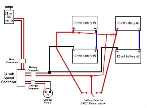
Well, I finally got my hands on the mobility scooter I posted about awhile back. As best I can make out, there are a couple of small wires with diodes that allow the unit to charge no matter what position the battery selector is in. I have batteries #1 and #4 as one 24 volt bank and batteries #2 and #3 as the other bank. I just had to work this out via common sense as the thing was a mess when I got it. It anyone has the time and knowledge to check my work, I sure would appreciate that. As it stands now, the speed controller is smoked, so I'm waiting on one of those to finish up. I can't really test the charging circuit as the batteries are all brand new and show full charge... once I can run the motor I'll know more but for now here is the circuit I came up with. Thanks in advance for any help or suggestions.
Ray


Fatdog,
Your circuit looks ok, except for one thing. Those diodes cause about a .7 to 1.2 volt drop in the charge voltage during charging, depending on their type and the charge current. So, that means the 24 volt battery sets won't come up to full charge unless the charger is properly adjusted for the normal float voltage for two 24 volt batteries, plus about 1 volt.
If it were me doing this, I would probably charge the batteries up to full charge, and then just connect them (the two 24 volt battery sets) directly in parallel without the two diodes, and without the switch. That way you always use all the batteries evenly, and you never have to worry about switching between the packs, and both packs always charge up fully though it just takes a bit longer. Nothing to think about except to put it back on charge when you are finished riding.
I charge the 5 battery string in my XB-600 after every day of use. The less you discharge the battery pack before recharging it, the longer it will last. Make sure you are using a good quality charger that will float the packs when they are charged, so they don't over charge.
That's about it, enjoy,
Tom
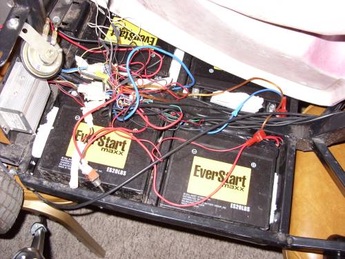
Thanks for checking, Tom. The owner of this is my neighbor, an 82 year young person with no drivers license. The switch saves him from getting stuck because when he hits the limit of one bank of batteries, he flips the switch and heads straight for home. The "Intelligent Charger" (that's to only English anywhere on anything connected with this scooter) puts out almost 29 volts so he should be OK. We get a new speed controller next week and he should be back on the road (well, sidewalk). He smoked the old controller trying to change the batteries himself without help, or notes, or photos... Here is what I saw when I opened it up... Yes, the brown wire is lamp cord he added.
Thanks Again, Ray
You can lead a horse to water, but if you can get it to float on it's back, THEN you've got something!