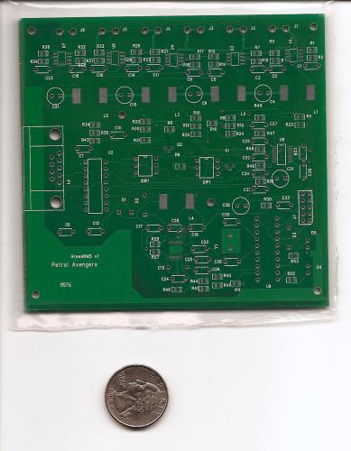
Dream GreenSaver Charger - The GreenBMS

I'm moving this from a post to a blog to keep people up to date with my progress.
For those who haven't been following the threads I've posted to here are the problems I'm trying to solve:
1) Battery charging- Make sure our batteries live long and prosper.
2) Equalizing- Make sure they discharge at an equal rate so you're range isn't limited by your weakest battery.
3) Cost- Keep the price lower than the alternatives.
4) Patents- Must do this all without violating patents.
After three weeks of heavy brainstorming here's the leading plan for what I call the GreenBMS:
More than anything, we need a good temperature compensated bank charger. So I'm building a percision, programable, multichemistry, bank charger that uses PWM to provide desulfication and active monitoring of each battery's voltage. Woah, try saying that with one breath (adjusts glasses). This is the heart of the GreenBMS. By using a chip that came to the market only a month ago, you can provide your own DC power source to the charger it can accept anything from 3-75 volts DC. (Anything above 14V means higher efficiency). It is small enough to fit inside the scooter. You can save money by using the charger that came with the bike to power it or buy something beefier. You can even connect it directly to solar panels if you wish.
Extra add-on 1 (An auxiliary battery):
The other benefit to having a power converter that takes such a large range of voltages is you can charge the batteries as you drive, like an alternator does, but it will get it's current from an auxiliary battery instead of a car's engine. You can run the 12V electronics off it and get rid of the inefficient DC-DC converter. The charger will switch to a mode that charges the weakest battery and brings it up to the average state of charge of all the batteries. If the batteries are evenly matched, the auxiliary battery will never discharge much. If all the batteries are very low, or if told to do so, it switches to an extend range mode, where the auxiliary battery charges all the batteries at a rate in which it will be depleted at the same all the other batteries are. When you plug it in, the auxiliary battery gets bank charged with all the other batteries. You can make the auxiliary battery any capacity and chemistry you want. A small cordless power tool battery might be all you need, I need to do testing once I build the prototype. The only cost of this add-on is the price of the battery and the wires to connect it.
Extra add-on 2 (a display, and user interface):
Since the microcontroller (uC) is already monitoring battery voltages, amps, and temperature, it's very simple to display this on an LCD. It will have a graphical user interface and some buttons to let you interact with the BMS' parameters.
Extra add-on 3 (wireless communications):
Everyone can change their programs if they wish to. I know everyone here loves to tinker and share their improvements. I'll offer a long range wireless (102.15.4) data communications add-on so you can program the charger, install updates, monitor the charging, and download data from your rides, from anywhere in your house. It's cheaper than bluetooth, and easier to interface.
This is all going to be opensource to keep costs for everyone to a minimum. I'm doing this project for myself, and making the knowledge on how to do it free for everyone. Early adopters of electric scooters have a soft place in my heart. I'll have extra circuit boards made up, buy enough parts to construct a dozen kits, and sell them in kit form or assembled for a bit extra.
This week I'll be drafting schematics and ordering components.
This project is much more complicated then initially planed. My fears are the cost of the parts, and the complexity of making them all work in harmony. In the past I've programed uC's. I went through a clock making phase. One clock flickered 8 leds fast when you attach it to the ceiling fan it displays the time. I've made a SMPS to power a nixie clock. It turned out well. This time I'll be programming a uC with the most sophisticated program ever. The SMPS this time is powerful enough if I put a wire in the wrong place it could start a fire. If you guys don't hear from me in a while, you can assume I forgot to ground something. :P
As a request: Everyone please take out your multimeters and tell me the resistance of your batteries and voltages before charging and after. Include the temperature as well. Thanks in advance.
-=Jeff=-
- sparc5's blog
- Log in or register to post comments
Who's online
There are currently 0 users online.
Who's new
- eric01
- Norberto
- sarim
- Edd
- OlaOst
Support V is for Voltage

Comments
Re: Dream GreenSaver Charger - The GreenBMS
Ok, but that display is only 1" diagonal. Is that too small for what you need?
This http://search.digikey.com/scripts/DkSearch/dksus.dll?Detail?name=73-1329-ND
seems to be almost 3" in size, has a serial IF and only $17.
But I know you probably "bought it now" :) so let me know if you want to look for an alternative.
For my project, I was using an ODM which were going to use their standard product as a baseline for my custom design. They would be manufacturing the product with their own stock of parts so I didn't get involved in part selection. If you want, I can query them on their LCD supplier. I have personally designed with Optrex LCD displays (above) and they worked well in the past.
I think I also found some flat flex connectors for the LCD:
http://search.digikey.com/scripts/DkSearch/dksus.dll?Cat=1442849
Re: Dream GreenSaver Charger - The GreenBMS
It is too small Kev. Got too excited. :)I like your choice better.
XM-3000...
-DC-DC converter replaced with a Dell D220P-01 power supply.
-72V mod
-Expensive bank charger until I come up with something better... Still trying.
-
Re: Dream GreenSaver Charger - The GreenBMS
No new info for the last 10 weeks?
Cheers, Gary
XM-5000Li, wired for cell voltage measuring and logging.
Re: Dream GreenSaver Charger - The GreenBMS
Has this Simple-BMS idea been tied?
For Balancing, if one measures the N cell voltages, and identified the
cell with the highest voltage (H), and the one with the lowest (L), and
if the difference in voltage between H and L is significant:
With electronic "switches", put a capacitor A across cell H and a 2nd capacitor
B across cell L. With the switches, swap the capacitors A and B about N times
per second.
Current will charge the capacitor when connected to H and discharge when
connected to L, gadually bringing the lowest cell up and the highest
cell down. This should work both when charging and when discharging.
Then, when H gets too high, the charger can be turned off.
When L gets too low, the load can be severely reduced.
The status of all the cells could optionally be displayed by LEDs or
other means, or communicated to another device.
Hereby published into the public domain, if not already patented,
the "Simple-BMS" cannot now be patented.
Cheers, Gary
XM-5000Li, wired for cell voltage measuring and logging.
Re: Dream GreenSaver Charger - The GreenBMS
Today was a good day.
XM-3000...
-DC-DC converter replaced with a Dell D220P-01 power supply.
-72V mod
-Expensive bank charger until I come up with something better... Still trying.
-
Re: Dream GreenSaver Charger - The GreenBMS
It really is green!
Any chance it could be used for NiMH batteries?
This information may be used entirely at your own risk.
There is always a way if there is no other way!
Pages