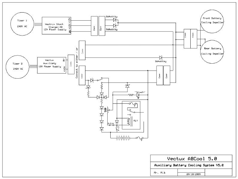
The ABCool simply puts 12V through the two cooling impellers in the Vectrix VX-1 and turns off the 12V supplied by the stock electronics (if they happen to be "ON" at the time).
Regardless of whether the ABCool is on or off, the stock electronics continue to function completely as usual.
The ABCool allows the cooling impellers to be turned on for as long as required, whenever a mains power supply (or a suitable battery) is available.
This usually leads to improved cooling of the Vectrix batteries during the initial hour or so of running the impellers. Maybe even more importantly, prolonged running of the impellers will gradually equalize the temperature of all cells, until they have all reached ambient air temperature. This helps to prevent state of charge imbalance caused by the strong temperature gradient that often develops in the VX-1 battery pack.
A timer or two can be added to the ABCool to enable fully automatic cooling prior to charging, as well as during and after charging.
As an alternative (or an add-on) to the 12V supply, a battery (between 8V and 12V) can be plugged in. This allows running of the impellers during riding, or when parking in the sun in places where no mains electricity is available.
If I manage to sell the ABCool 4.0 No 0001, then I will include an extra connector, so that a battery can easily be plugged into the existing ABCool.
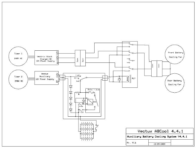
And the ABCool development is continuing: I am currently working on a design that will automatically recharge an auxiliary battery whenever the ABCool is plugged into the mains. This battery can then be used to power the impellers when no mains power is available (during riding or parking), or even whilst plugged in. The batteries will probably run the impellers at a reduced speed; but higher speed (up to 15V DC) is probably also possible.
But that is only partially tested so far - the diagram below shows the principle but might still contain errors.
This add-on device will plug straight into the ABCool 4.0, between the 12V supply and the rest of it:
This information may be used entirely at your own risk.
There are some differences between the previous prototype ABCool and the ABCool 4.0 - mainly to allow much easier installation and de-installation. The core components (power supply and relay) are however exactly the same as in the ABCool which I have been using almost daily since I finished reworking the battery in early January 2009. It has been working without a glitch.
A) The connectors now match the original connectors of the VX-1, so that the ABCool can be plugged in without any irreversible changes to the Vectrix.
B) Velcro straps are integrated into the design to allow reversible fastening. It is however better to put proper cable ties on top of the velcro straps - to be sure to be sure that it will never come loose!
.
.
Installation is quite easy:
1) lift up the rear seat.
2) undo the two bolts holding the front seat (using a 10mm ring spanner, the only tool needed!)
3) slide the seat forward and down to release it from the hook holding it's front down, put the seat aside.
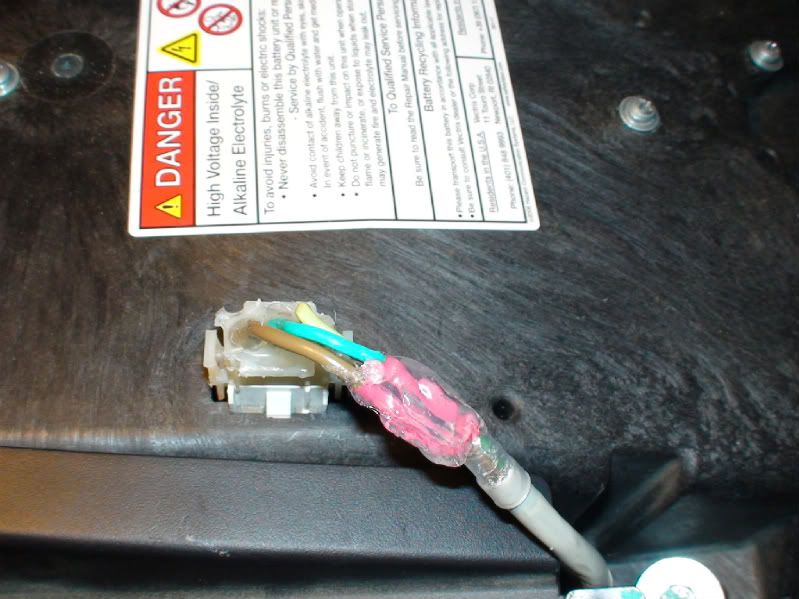
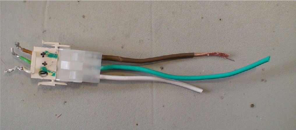
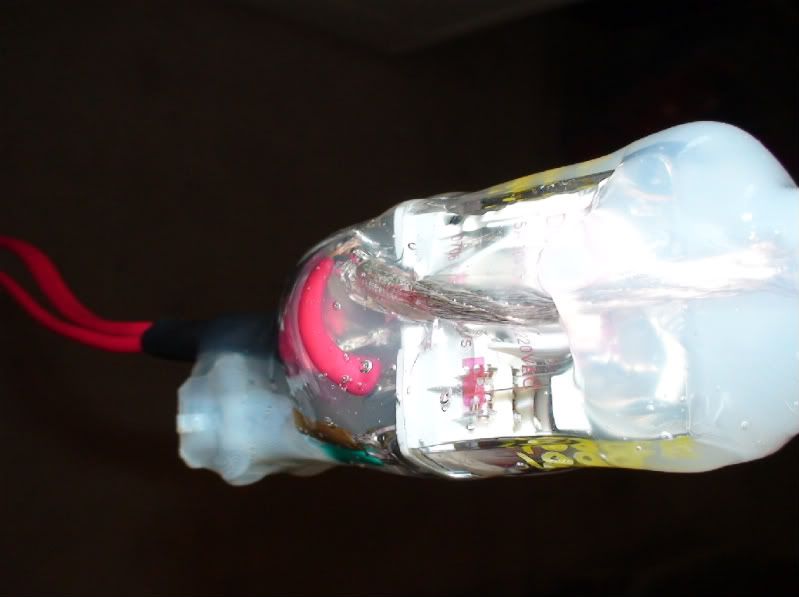
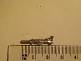
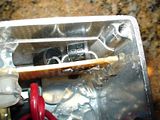
4) unplug the connector on top of the battery container by pressing on both (narrow) sides and pull it off:
(The picture of the connector shown here was taken after restoration of the Vectux to it's original configuration - to allow realistic plug-and-play testing of the ABCool 4.0 design. Usually the three cables do not have the hot glue bulge which contains the repair job).
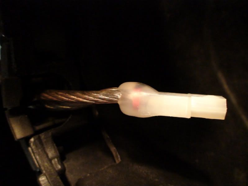
5) plug the now loose end of the Vectrix connector into the connector in the middle of the ABCool and fasten the black velcro strap around the connector to ensure it will not rattle loose. It will only fit in the correct position. Make sure it is pushed in all the way - until the two retaining clips on the sides have engaged.
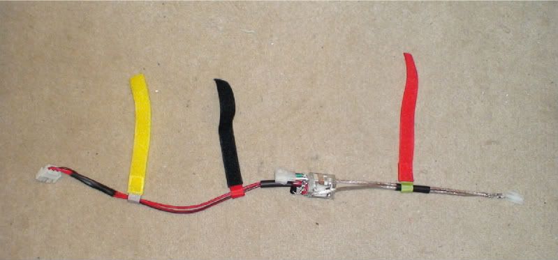
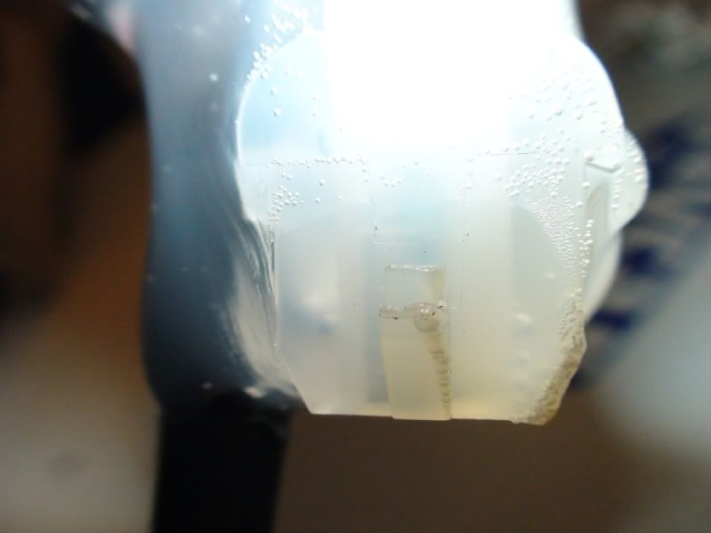
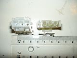
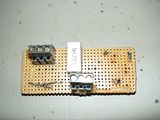
This picture shows the ABCool before it is encased in hot melt glue:
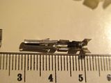
And here is a close-up of the three connectors on the finished ABCool 4.0:
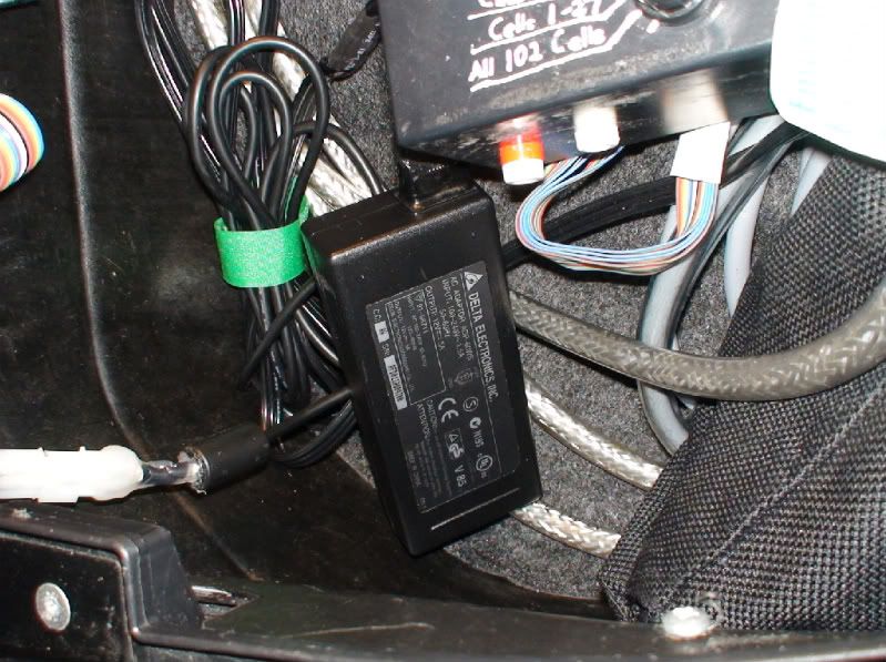
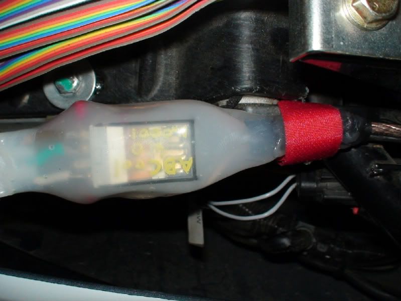
6) fasten the yellow velcro strap around the black plastic conduit and around the original cable, on the left side of the battery container:
7)fasten the red velcro strap firmly around the frame next to the silver metal plate. This turns the hot glue casing into a shock absorber so that the relay does not malfunction on bumpy roads:
Take care not to wrap the red velcro strap around the cable and connector for the boot light switch shown in this photo:
The cable at the boot end of the ABCool is long enough to be placed into the boot through the cable gap in the corner of the boot, or it can stay outside of the boot.
8) replace the front seat and tighten the two bolts, making sure that the front end of the seat has firmly engaged with the hook holding it down.
Done!
All thats left to see of it is this:
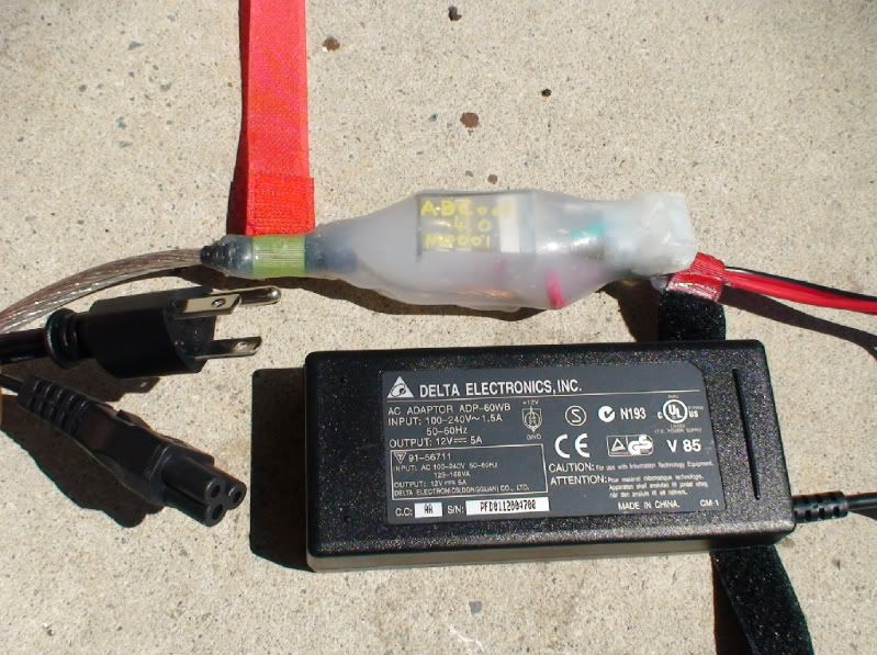
9) When you want to use the ABCool, plug in the 12V power supply into the 2 pole connector and plug the power supply into a 120V - 240V 50Hz supply. Both cooling impellers will start to run and force air through the batteries for as long as the mains power stays on.
The power supply will get hot if it does not get some access to cooling air flow. I mounted the power supply of the previous model close to where the red velcro strap fastens the 4.0 model as described above. I waterproofed the previous power supply with "liquid electrical tape" and never had any problems with water ingress or overheating; there is always a bit of air flow around that location.
I am however not prepared to sell a mains voltage product which was not designed for outdoor use to be used outdoors. If you want to mount the power supply permanently on your Vectrix, you need to waterproof the power supply yourself at your own risk.
Ideally the ABCool should only be used with the power supply out of the boot, with air flow possible around it.
The ABCool 4.0 has worked well for 4 days in the boot up until today, but the weather has not been hot, just up to 25degC or so. If you leave the 12V power supply in the boot whilst it is running, then you must make sure that it is not covered up by any heat insulating items like gloves, rain gear, woolen jumpers or whatever else you keep in the boot. It must not touch things with it's sides, otherwise it could overheat!
This should work:
I'm not sure if the heat production of the power supply is different when it is used on a grid supply with less than 240V - I cannot test this.
.
Similarly to the no waterproofing / outdoor use issue, I will only supply the original mains voltage cable with the plug that it came with. I have made no changes to any parts carrying dangerous voltages!
Is this a USA plug?:
I think it would be easy to either get an electrician to install a different mains plug on the cable if needed, or to find a suitable cable (for example from a computer monitor power supply).
.
.
Coming up next: More details on how to build your own ABCool.
This information may be used entirely at your own risk.
And because I should not be posting items for sale ouside of the commercial section on VisforVoltage…..
But, I claim that this is a special case. If I only posted this in the commercial section it might get missed by many Vectrix owners who might want to build their own. After all, the ABCool is designed to correct the key vulnerability of the Vectrix battery pack: heat and temperature gradients which cause ageing, charge loss and imbalance.
So I’m not just selling something, I’m also showing how you could build your own cheaper than you could buy it off me. At least if you are time-rich.
Making an ABCool well, takes time, which is at a premium. I basically spent an entire Saturday morning building this first ABCool 4.0 unit.
No doubt this process will become easier and faster if I end up building more units, because I would not endlessly repeat the same errors which were slowing things down.
I guess that’s what R+D is about.
There would also be less material costs, because eventually I would know exactly how long to cut the cables, so that there are fewer offcuts. And material and shipping costs might go down if I buy relays and / or power supplies in bulk.
But for now it takes a lot of time, and I do of course not work for third world sweatshop rates….
This first ABCool 4.0 unit was built for my own use. And that is my quality control principle:
I offer the device for sale on ebay, with a starting price that I find sufficient to justify giving up another bunch of hours on the next weekend (to build myself a new ABCool). If it does not sell for that price, no problem, I will happily keep it because it is well built and should last a long time!
And I consider it an essential accessory, particularly with the older firmware running in the Vectux.
I hope you guys bid like crazy and it sells for enough money to help me finance a few extra purchases for the budding electronics workshop. I’m thinking isolating transformer, Variac, oscilloscope, high current CBA2 unit, etc.
If that’s the case then I’ll probably ramp up production and build 2 or more units at once the next time, but I will still road test them individually before selling.
Eventually I could probably do a batch of 10 ABCool units at a time, but I guess by then the design will have changed to a better one yet again…
So, to be honest, you could probably buy the tools and materials needed to build your own ABCool for the price I am expecting for just one of them. They will seem very expensive, compared to other (mass produced) electronics devices.
And you might suffer the same trouble which you are already used to as a Vectrix owner: Early adopter premium price, no warranty, the gizmo might be available much cheaper a little later, the next version might be much better, etc. etc.
But, you might also end up buying the first or the last ABCool ever sold (or both!), owning yet another rare collector’s item …!
This information may be used entirely at your own risk.
Here are the details about how you can build you own ABCool.
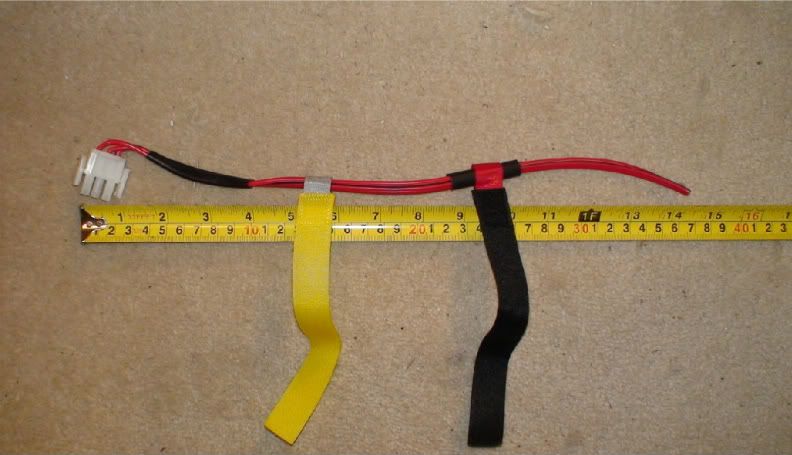
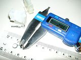
Start with three cables: I used 15A rated automotive cable, although only 5A will be going through the common ground (and 2.5A through each positive cable).
Crimp and solder female pins to each cable and push them into the 3-pole male connector.
Slide shrink wrap and velcro over the cables before soldering the other ends to the relay. Do not heat the shrink wrap until later on, when you can see where exactly they need to be.
The cables shown here are too long. Next time I’ll hopefully be more organized and measure the offcuts, so that I’ll know exactly how long to cut the cables from then on.
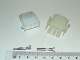
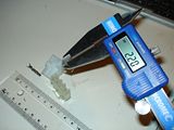
Attach three short cables to the female 3-pole connector, again crimped and soldered. Colour matching with the original Vectrix male connector counterpart helps to avoid confusion and makes sure that they will fit together.
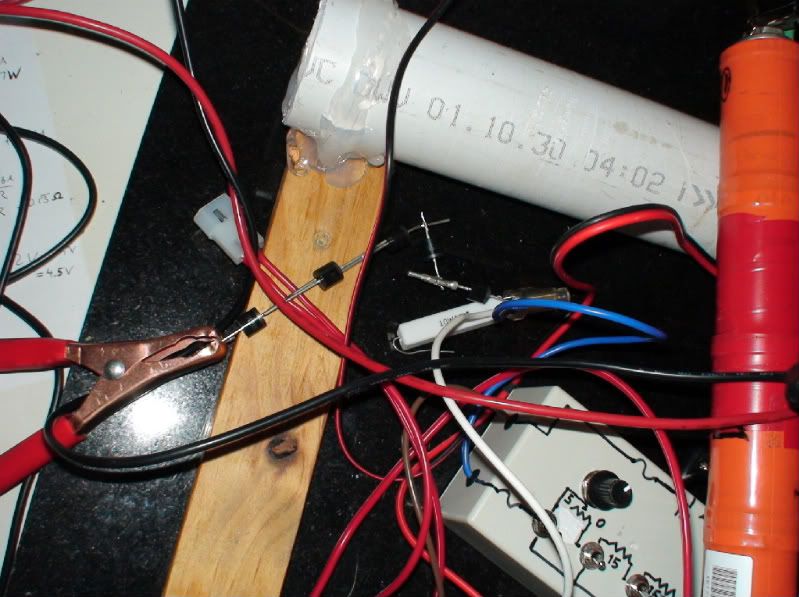
Cut a length of figure-eight cable. I would use a longer one than shown here (next time!), to enable easier integration with the planned next part of the ABCool (the battery current source described above). The cable I used is way thicker than it needs to be, but it adds structural stability and some bounce to the hot glue cover going on later. Together they work as a shock absorber against vibrations during riding, which could otherwise cause the relay to turn on and off repeatedly.
This cable also looks nice; it’s the part of the ABCool which is visible when you open the rear seat to get to the charging cable. Unfortunately, thick cable makes it much more difficult to get a good solder connection to the relay contacts. A fat cable is such an excellent heat sink! Either use fairly decent soldering tools or thinner cables.
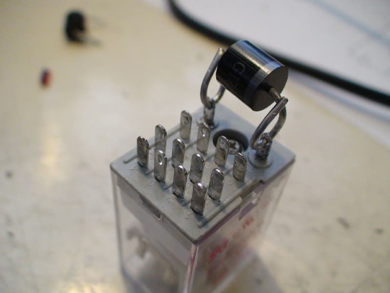
Tin the contacts on the relay and drill the holes for the diode terminals bigger if needed.
The diode I used is most likely overkill, it’s rated for 6A, but it’s what I had lying around already. It’s function is to short the energy stored in the relay coil through the coil when the relay is being turned off; this prevents a voltage spike that could potentially damage sensitive electronic components in the Vectrix.
Solder tinned cables and diode terminals to the relay coil terminals:
Solder tinned ends of the short female connector cables to the relay terminals:
.
.
Solder the tinned ends of the long cables (with the male connector) to the relay terminals:
.
.
Slide on a velcro strap, then crimp and solder pins to the ends of the fancy thick cable. Attaching some sort of indicator for positive and negative terminal would be a good idea. The cable I used is silver on the negative side, copper-reddish on the positive side. In addition, I added a red and a black shrink-wrap ring before pushing on the plastic part of the connector.
I don’t know what would happen if you get the polarity wrong. The relay will switch on, regardless of polarity, but the impellers could either run backwards, or do nothing, or let the magic smoke out. I’m not keen to try it out!
.
.
Then measure continuity between all the various connector terminals to check that you have put it together correctly.
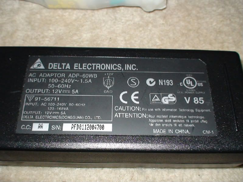
If it all adds up nicely, attach a corresponding 2-pole connector with correct polarity to a 12V (5A continuous) power supply or battery.
I used this one:
.
Then put 12V through the thing and measure with a multimeter what happens.
Don’t try it out on your Vectrix before you are certain!
Are all the polarities correct? Does the voltage come on and off appropriately when the relay switches?
Then, aaarghhh!, de-solder any incorrectly attached cables (in this case, the one soldered to 11 needed to be on 10) and re-solder in the right place:
.
Then test it again very carefully.
.
.
Once it is all put together correctly, plug it into your Vectrix and turn on the charger to check that the impellers run as they should. Then turn the charger off, and test if the auxiliary power supply is also turning on the impellers.
Then check that it works when both charger and ABCool are powered up. If it is working correctly, then the ABCool will be powering the impellers, not the stock 12V supply.
Once the ABCool has been verified to be working as it should, find the right places for the shrink-wrap and the velcro, and fixate them in place, using a hot air gun and hot glue.
Cover it all up with layers upon layers of hot melt glue. I used three big sticks for this one! You’ll need to rotate and tilt it continuously, a bit like glass-blowing, to get it to set where it is needed. Leave it to cool down between multiple sessions of hot glue application.
Then you may want to tidy up the surface of the resulting glue blob with a hot air gun, but be careful not to melt the plastic parts of the connectors!
I burned the edges a little bit, but it still engages properly with its counter-part. It would be easy to stuff up the whole thing at this stage, though!
.
This picture shows hot and cool parts of the growing glue cover around the relay body. The hot parts are clear, the cooler parts opaque:
Finally, integrate the last, red velcro strap into the hot glue cover so that it cannot slide off later.
.
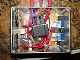
Add hot glue to the connectors to "ruggedize "the device against corrosion, damage due to vibration, and kinking:
And there you go, all done!
This information may be used entirely at your own risk.
Re: ABCool 4.0 - Vectrix Auxiliary Battery Cooling system
Got some good news and some bad news.
The good: The NHW10 battery charged to almost completely full through the prototype ABCool 4.4 setup with 5 diodes in series. The charging current after 70hrs was about 100mA, or C/65.
That means (I think) that with two NHW10 sticks in parallel the charge current at full state would be C/130.
The bad: The connectors which I have available to put inside the plastic connector housing are of a slightly different size compared to the ones used in the Vectrix.
I think it is an "imperial vs metric" problem.
The male plastic connectors contain the female metal pins (or what is the right name for them little buggers???).
It is too hard to get them to go in. They are a little too wide and need to be squeezed together first.
Similarly, they do not fit well onto the male pins in the Vectrix. A touch wobbly!
The size difference must be just a fraction of a millimeter.
But what it means is that the female pins in the original Vectrix connector will get bent open ever so slightly when connected to the ABCool. They might need a little squeeze with long-nosed pliers or something similar if/when the ABCool is being removed from a Vectrix. And that might cost you your (non-existing) warranty.
But it's usually best to be honest anyway. And the ABCool is designed to protect the battery, not the warranty.
You just have to decide what is more important!
Or find the right pins and tell us all about it!
.
Click pictures to enlarge.
This information may be used entirely at your own risk.
...
I am currently working on a design that will automatically recharge an auxiliary battery whenever the ABCool is plugged into the mains. This battery can then be used to power the impellers when no mains power is available (during riding or parking), or even whilst plugged in. The batteries will probably run the impellers at a reduced speed; but higher speed (up to 15V DC) is probably also possible.
But that is only partially tested so far - the diagram below shows the principle but might still contain errors.
This add-on device will plug straight into the ABCool 4.0, between the 12V supply and the rest of it:
So far the recharging part of this idea seems to work well. But I found that the extra relay will not work the way I was hoping. The relays I have tested just do not turn themselves off again when the voltage drops. They require around 8 to 9V to turn on, but once they are on, they stay on all the way down to 3V.
So I'm looking for an easy way to turn the ABCool battery off when (or just before) the battery voltage has dropped to about 7.5V ; at that point one of the impellers will constantly turn on and off. I got an idea fermenting away in the back of my head, something with a momentary on switch, a capacitor and a resistor.
Some people are wondering why I use this (unusual?) set of serial diodes.
Here is something from a pm:
Why all the diodes in series for the charge circuit? Why not use a 10ohm 1 or 2 watt resistor? It will be self regulating. As the battery voltage increases the current will decrease.
I might of course have it all wrong, but my reasoning goes like this (and my experiments do so far support it):
With a resistor the current will always continue to flow, because the voltage drop reduces when the current reduces.
The current flow with an empty 6s battery of 7.2V needs to remain below 1A, to allow the impellers to continue running using their 4A. (Due t the 5A limit of the power supply I use).
12V-7.2V = 4.8V
4.8V/1A = R --> R = 4.8Ohm or thereabouts.
When the battery is full at 8.7V, the voltage differential of 12V-8.7V=3.3V would still allow 3.3V/4.8Ohm= 688mA to flow, more than C/10. This would overheat the battery.
With a 10 Ohm resistor the initial current cannot be higher than 480mA; and the current at 8.7V would be about 333mA, which is about C/20 for the 6.5Ah batteries. It would take way too long to charge the batteries due to the low starting current, and the C/20 rate at the end would be too high to leave it on constantly.
Diodes have an almost "fixed" voltage drop and 5*0.71V = 3.55V; 12-3.55 = 8.45V .
When the circuit is open, the voltage drop seems to reduce and I measure just over 10V, but as soon as the battery draws a little current, the voltage is limited to 8.45V. The batteries can probably take this continuously for extended time periods without getting damaged.
That allows to plug it in and forget it. Half a year later, when you cannot find a shady spot to park on a really hot day, you'll have a fully charged and undamaged battery to give you a few hours of temperature-imbalance-prevention!
When you have used up the charge in this auxiliary battery, it will recharge at a reasonably fast rate, because the lower the battery voltage, the more current the diodes let through! They are rated at 6A, but the maximum charging current will be less than that. I hope that the ABCool battery will almost fully recharge during the time needed for a Vectrix charge including pre-and post cooling periods, about 8 hrs or so.
So with the diodes, the ABCool battery could be used on the way to work, and again on the way home, on the same day.
Hope that makes sense. I have only tested the recharging part yet. I need to put the ingredients into a box so that I can connect it to the Vectux ABCool. At the moment the prototype is a mess of cables on the bench!
I don't want to ride around with that in the boot!
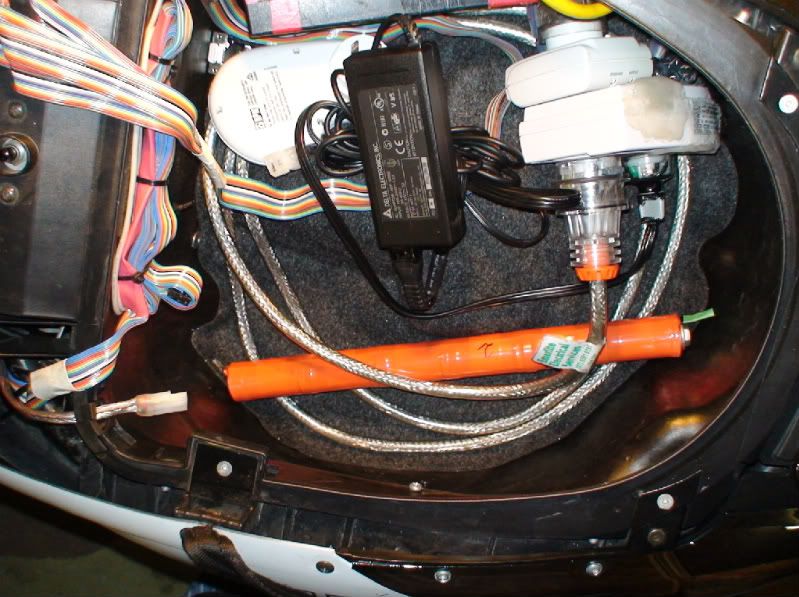
But eventually it will be a nice fit. Here is how these NHW10 sticks fit in the boot:
This information may be used entirely at your own risk.
Re: ABCool 4.0 - Vectrix Auxiliary Battery Cooling system
The ABCool 4.0 No0001 has not been working perfectly during the 10 days of testing so far.
On a few occasions the impellers failed to start when they should have. I think it is due to a manufacturing fault in the relay, it seems to not close the contact properly sometimes.
It might also be due to heat damage from soldering.
Because of this I have increased the ‘handling time” on the ebay offer to 5 working days; this will allow me to build and test a new unit in time.
The delay and rework allows the inclusion of two design improvements into the first unit for sale:
Number one is that two poles in the 4-pole relay will be used in parallel as the negative pole. This adds redundancy against failure of that relay contact which was previously used as the single negative pole, by adding in the previously unused fourth pole. (I suspect it is this one that causes the trouble in unit No0001, because one impeller should turn on if it was one of the +12V poles; but it’s always both impellers failing to start when it happens). This will also reduce the current through that pole to around 2A so that it is not running close to it’s 5A rating all the time. It will be more reliable, heat up less and “live longer” that way!
Improvement Nr2 relates to easier forward compatibility with the ABCool battery add-on which I am working on. It is coming along nicely, and it will have 3-pole connectors when it’s ready. That means that future add-ons will probably be backward-compatible without changing the connectors.
.
I thought about my “No Warranty” policy and came up with a way around the moral problems which this poses:
Offering a one week money back option.
If someone buys an ABCool off me but does not like it for whatever reason, s/he can just return the item within a week and get the full purchase price back when I have the ABCool back. (But postage is at the buyers expense.)
Having a week to test and decide if s/he wants to keep the item without any warranty should in my opinion fully compensate for the absence of a warranty.
This information may be used entirely at your own risk.
Re: ABCool 4.0 - Vectrix Auxiliary Battery Cooling system
...
Because of this I have increased the ‘handling time” on the ebay offer to 5 working days; this will allow me to build and test a new unit in time.
...
It's built and is so far showing flawless performance.
Here is the schematic of the ABCool 4.0.2:
I used a 1A rated diode at the relay, three pole connectors throughout (one pole unused in two of them), and slightly different velcro straps than in the fist unit. It took about three hours to put together this time.
This information may be used entirely at your own risk.
Re: ABCool 4.0 - Vectrix Auxiliary Battery Cooling system
Well, the darn thing did not sell!
So much for my attempt to turn a lemon into lemonade...HAHA!
I'm sorry to hear that... I can only speak for myself.
My reasons to not buy were:
- My bike is "still in warranty";
- My knowledge about electronics is very low and I'm afraid doing something wrong in installation.
My experience and concerns about cooling down the battery tell me that your device is a great help. It could be replaced by a firmware patch that could introduce a specific timer for extra ventilation, but since that will not happen, your device becomes a great option.
I think I have now figured out what goes wrong. The old ABCool design with a relay instead of diode OR-ing would have prevented the disaster!
For reasons which I do not fully understand the device causes a DC voltage between Earth and each single battery cell tab in the M-BMS!
And as I know now, USB cables are earthed. So when I connected the CBA II to the battery tabs 3 and 4, a 42V DC shock went through the CBA II to my laptop. I don't know yet if it has also fried the CBA II on the way through. I'm a bit apprehensive about plugging it into my last remaining computer to try it out!
The about 40V DC between tabs and Earth occur as soon as the plug of the auxiliary power supply is plugged into a power outlet, even if the outlet is turned off. Turning the power point off disconnects the Active pole, I think. So it must be due to Neutral or Earth making contact.
Unplugging the connector going to the impellers does not change this, the effect happens because of the negative cable from ABCool to stock (charger) electronics. As soon as I connect just the negative pole of the auxiliary power supply to the diode OR-ing cable, the 40V DC appear between tabs and Earth. It does not matter if the auxiliary power supply is connected through the box of diodes and resistors, or straight to the cable with the OR-ing diodes.
This information may be used entirely at your own risk.


The ABCool simply puts 12V through the two cooling impellers in the Vectrix VX-1 and turns off the 12V supplied by the stock electronics (if they happen to be "ON" at the time).
Regardless of whether the ABCool is on or off, the stock electronics continue to function completely as usual.
The ABCool allows the cooling impellers to be turned on for as long as required, whenever a mains power supply (or a suitable battery) is available.
This usually leads to improved cooling of the Vectrix batteries during the initial hour or so of running the impellers. Maybe even more importantly, prolonged running of the impellers will gradually equalize the temperature of all cells, until they have all reached ambient air temperature. This helps to prevent state of charge imbalance caused by the strong temperature gradient that often develops in the VX-1 battery pack.
A timer or two can be added to the ABCool to enable fully automatic cooling prior to charging, as well as during and after charging.
As an alternative (or an add-on) to the 12V supply, a battery (between 8V and 12V) can be plugged in. This allows running of the impellers during riding, or when parking in the sun in places where no mains electricity is available.
If I manage to sell the ABCool 4.0 No 0001, then I will include an extra connector, so that a battery can easily be plugged into the existing ABCool.
And the ABCool development is continuing: I am currently working on a design that will automatically recharge an auxiliary battery whenever the ABCool is plugged into the mains. This battery can then be used to power the impellers when no mains power is available (during riding or parking), or even whilst plugged in. The batteries will probably run the impellers at a reduced speed; but higher speed (up to 15V DC) is probably also possible.
But that is only partially tested so far - the diagram below shows the principle but might still contain errors.
This add-on device will plug straight into the ABCool 4.0, between the 12V supply and the rest of it:
This information may be used entirely at your own risk.
There is always a way if there is no other way!
There are some differences between the previous prototype ABCool and the ABCool 4.0 - mainly to allow much easier installation and de-installation. The core components (power supply and relay) are however exactly the same as in the ABCool which I have been using almost daily since I finished reworking the battery in early January 2009. It has been working without a glitch.
A) The connectors now match the original connectors of the VX-1, so that the ABCool can be plugged in without any irreversible changes to the Vectrix.
B) Velcro straps are integrated into the design to allow reversible fastening. It is however better to put proper cable ties on top of the velcro straps - to be sure to be sure that it will never come loose!
.
.
Installation is quite easy:
1) lift up the rear seat.
2) undo the two bolts holding the front seat (using a 10mm ring spanner, the only tool needed!)
3) slide the seat forward and down to release it from the hook holding it's front down, put the seat aside.
4) unplug the connector on top of the battery container by pressing on both (narrow) sides and pull it off:
(The picture of the connector shown here was taken after restoration of the Vectux to it's original configuration - to allow realistic plug-and-play testing of the ABCool 4.0 design. Usually the three cables do not have the hot glue bulge which contains the repair job).
5) plug the now loose end of the Vectrix connector into the connector in the middle of the ABCool and fasten the black velcro strap around the connector to ensure it will not rattle loose. It will only fit in the correct position. Make sure it is pushed in all the way - until the two retaining clips on the sides have engaged.
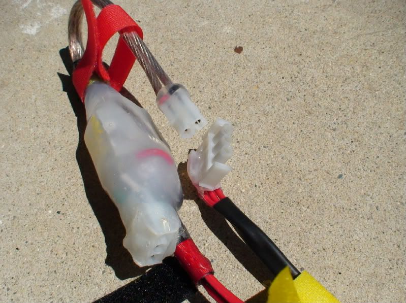
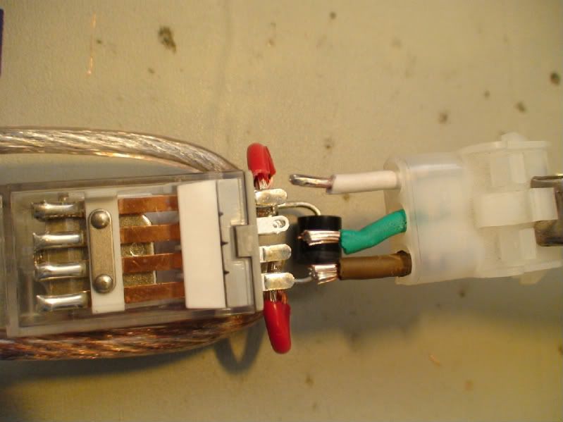
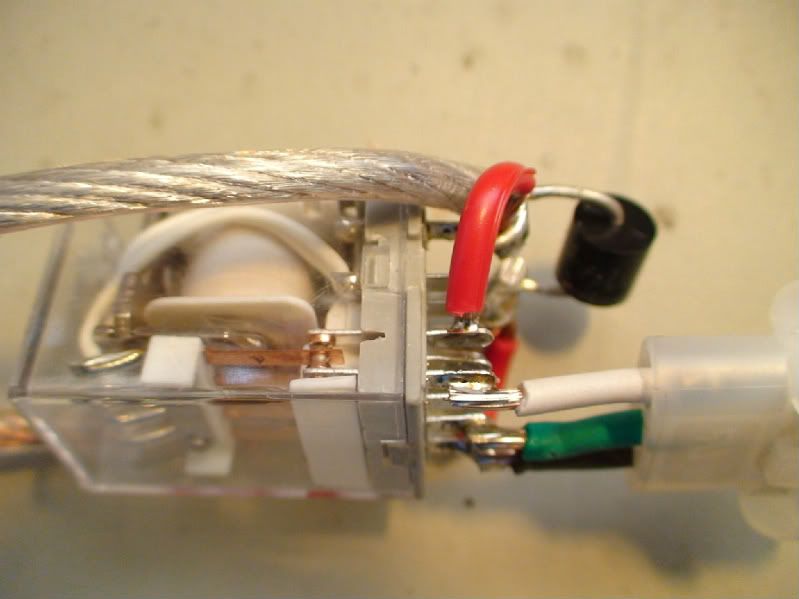
This picture shows the ABCool before it is encased in hot melt glue:
And here is a close-up of the three connectors on the finished ABCool 4.0:
6) fasten the yellow velcro strap around the black plastic conduit and around the original cable, on the left side of the battery container:
7)fasten the red velcro strap firmly around the frame next to the silver metal plate. This turns the hot glue casing into a shock absorber so that the relay does not malfunction on bumpy roads:
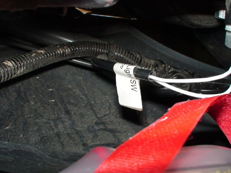
Take care not to wrap the red velcro strap around the cable and connector for the boot light switch shown in this photo:
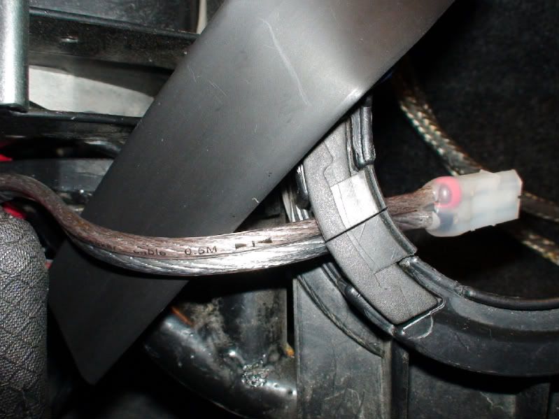
The cable at the boot end of the ABCool is long enough to be placed into the boot through the cable gap in the corner of the boot, or it can stay outside of the boot.
8) replace the front seat and tighten the two bolts, making sure that the front end of the seat has firmly engaged with the hook holding it down.
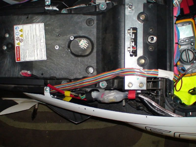
Done!
All thats left to see of it is this:

9) When you want to use the ABCool, plug in the 12V power supply into the 2 pole connector and plug the power supply into a 120V - 240V 50Hz supply. Both cooling impellers will start to run and force air through the batteries for as long as the mains power stays on.
The power supply will get hot if it does not get some access to cooling air flow. I mounted the power supply of the previous model close to where the red velcro strap fastens the 4.0 model as described above. I waterproofed the previous power supply with "liquid electrical tape" and never had any problems with water ingress or overheating; there is always a bit of air flow around that location.
I am however not prepared to sell a mains voltage product which was not designed for outdoor use to be used outdoors. If you want to mount the power supply permanently on your Vectrix, you need to waterproof the power supply yourself at your own risk.
Ideally the ABCool should only be used with the power supply out of the boot, with air flow possible around it.
The ABCool 4.0 has worked well for 4 days in the boot up until today, but the weather has not been hot, just up to 25degC or so. If you leave the 12V power supply in the boot whilst it is running, then you must make sure that it is not covered up by any heat insulating items like gloves, rain gear, woolen jumpers or whatever else you keep in the boot. It must not touch things with it's sides, otherwise it could overheat!
This should work:
I'm not sure if the heat production of the power supply is different when it is used on a grid supply with less than 240V - I cannot test this.
.
Similarly to the no waterproofing / outdoor use issue, I will only supply the original mains voltage cable with the plug that it came with. I have made no changes to any parts carrying dangerous voltages!
Is this a USA plug?:
I think it would be easy to either get an electrician to install a different mains plug on the cable if needed, or to find a suitable cable (for example from a computer monitor power supply).
.
.
Coming up next: More details on how to build your own ABCool.
This information may be used entirely at your own risk.
There is always a way if there is no other way!
Yup, that's a good ol' American plug. Best there is, son.
They don't always have the ground, though.
Thanks for your ABCool development! One of these days, when my batteries are back in, I'll install one.
Ron
In short: because it will be expensive to buy!
And because I should not be posting items for sale ouside of the commercial section on VisforVoltage…..
But, I claim that this is a special case. If I only posted this in the commercial section it might get missed by many Vectrix owners who might want to build their own. After all, the ABCool is designed to correct the key vulnerability of the Vectrix battery pack: heat and temperature gradients which cause ageing, charge loss and imbalance.
So I’m not just selling something, I’m also showing how you could build your own cheaper than you could buy it off me. At least if you are time-rich.
Making an ABCool well, takes time, which is at a premium. I basically spent an entire Saturday morning building this first ABCool 4.0 unit.
No doubt this process will become easier and faster if I end up building more units, because I would not endlessly repeat the same errors which were slowing things down.
I guess that’s what R+D is about.
There would also be less material costs, because eventually I would know exactly how long to cut the cables, so that there are fewer offcuts. And material and shipping costs might go down if I buy relays and / or power supplies in bulk.
But for now it takes a lot of time, and I do of course not work for third world sweatshop rates….
This first ABCool 4.0 unit was built for my own use. And that is my quality control principle:
I offer the device for sale on ebay, with a starting price that I find sufficient to justify giving up another bunch of hours on the next weekend (to build myself a new ABCool). If it does not sell for that price, no problem, I will happily keep it because it is well built and should last a long time!
And I consider it an essential accessory, particularly with the older firmware running in the Vectux.
I hope you guys bid like crazy and it sells for enough money to help me finance a few extra purchases for the budding electronics workshop. I’m thinking isolating transformer, Variac, oscilloscope, high current CBA2 unit, etc.
If that’s the case then I’ll probably ramp up production and build 2 or more units at once the next time, but I will still road test them individually before selling.
Eventually I could probably do a batch of 10 ABCool units at a time, but I guess by then the design will have changed to a better one yet again…
So, to be honest, you could probably buy the tools and materials needed to build your own ABCool for the price I am expecting for just one of them. They will seem very expensive, compared to other (mass produced) electronics devices.
And you might suffer the same trouble which you are already used to as a Vectrix owner: Early adopter premium price, no warranty, the gizmo might be available much cheaper a little later, the next version might be much better, etc. etc.
But, you might also end up buying the first or the last ABCool ever sold (or both!), owning yet another rare collector’s item …!
This information may be used entirely at your own risk.
There is always a way if there is no other way!
Here are the details about how you can build you own ABCool.
Start with three cables: I used 15A rated automotive cable, although only 5A will be going through the common ground (and 2.5A through each positive cable).
Crimp and solder female pins to each cable and push them into the 3-pole male connector.
Slide shrink wrap and velcro over the cables before soldering the other ends to the relay. Do not heat the shrink wrap until later on, when you can see where exactly they need to be.
The cables shown here are too long. Next time I’ll hopefully be more organized and measure the offcuts, so that I’ll know exactly how long to cut the cables from then on.
Attach three short cables to the female 3-pole connector, again crimped and soldered. Colour matching with the original Vectrix male connector counterpart helps to avoid confusion and makes sure that they will fit together.
Cut a length of figure-eight cable. I would use a longer one than shown here (next time!), to enable easier integration with the planned next part of the ABCool (the battery current source described above). The cable I used is way thicker than it needs to be, but it adds structural stability and some bounce to the hot glue cover going on later. Together they work as a shock absorber against vibrations during riding, which could otherwise cause the relay to turn on and off repeatedly.
This cable also looks nice; it’s the part of the ABCool which is visible when you open the rear seat to get to the charging cable. Unfortunately, thick cable makes it much more difficult to get a good solder connection to the relay contacts. A fat cable is such an excellent heat sink! Either use fairly decent soldering tools or thinner cables.
Tin the contacts on the relay and drill the holes for the diode terminals bigger if needed.
The diode I used is most likely overkill, it’s rated for 6A, but it’s what I had lying around already. It’s function is to short the energy stored in the relay coil through the coil when the relay is being turned off; this prevents a voltage spike that could potentially damage sensitive electronic components in the Vectrix.
Solder tinned cables and diode terminals to the relay coil terminals:
Solder tinned ends of the short female connector cables to the relay terminals:
.
.
Solder the tinned ends of the long cables (with the male connector) to the relay terminals:
.
.
Slide on a velcro strap, then crimp and solder pins to the ends of the fancy thick cable. Attaching some sort of indicator for positive and negative terminal would be a good idea. The cable I used is silver on the negative side, copper-reddish on the positive side. In addition, I added a red and a black shrink-wrap ring before pushing on the plastic part of the connector.
I don’t know what would happen if you get the polarity wrong. The relay will switch on, regardless of polarity, but the impellers could either run backwards, or do nothing, or let the magic smoke out. I’m not keen to try it out!
.
.
Then measure continuity between all the various connector terminals to check that you have put it together correctly.
If it all adds up nicely, attach a corresponding 2-pole connector with correct polarity to a 12V (5A continuous) power supply or battery.
I used this one:
.
Then put 12V through the thing and measure with a multimeter what happens.
Don’t try it out on your Vectrix before you are certain!
Are all the polarities correct? Does the voltage come on and off appropriately when the relay switches?
Then, aaarghhh!, de-solder any incorrectly attached cables (in this case, the one soldered to 11 needed to be on 10) and re-solder in the right place:
.
Then test it again very carefully.
.
.
Once it is all put together correctly, plug it into your Vectrix and turn on the charger to check that the impellers run as they should. Then turn the charger off, and test if the auxiliary power supply is also turning on the impellers.
Then check that it works when both charger and ABCool are powered up. If it is working correctly, then the ABCool will be powering the impellers, not the stock 12V supply.
Once the ABCool has been verified to be working as it should, find the right places for the shrink-wrap and the velcro, and fixate them in place, using a hot air gun and hot glue.
Cover it all up with layers upon layers of hot melt glue. I used three big sticks for this one! You’ll need to rotate and tilt it continuously, a bit like glass-blowing, to get it to set where it is needed. Leave it to cool down between multiple sessions of hot glue application.
Then you may want to tidy up the surface of the resulting glue blob with a hot air gun, but be careful not to melt the plastic parts of the connectors!
I burned the edges a little bit, but it still engages properly with its counter-part. It would be easy to stuff up the whole thing at this stage, though!
.
This picture shows hot and cool parts of the growing glue cover around the relay body. The hot parts are clear, the cooler parts opaque:
Finally, integrate the last, red velcro strap into the hot glue cover so that it cannot slide off later.
.
Add hot glue to the connectors to "ruggedize "the device against corrosion, damage due to vibration, and kinking:
And there you go, all done!
This information may be used entirely at your own risk.
There is always a way if there is no other way!
Got some good news and some bad news.
The good: The NHW10 battery charged to almost completely full through the prototype ABCool 4.4 setup with 5 diodes in series. The charging current after 70hrs was about 100mA, or C/65.
That means (I think) that with two NHW10 sticks in parallel the charge current at full state would be C/130.
The bad: The connectors which I have available to put inside the plastic connector housing are of a slightly different size compared to the ones used in the Vectrix.
I think it is an "imperial vs metric" problem.
The male plastic connectors contain the female metal pins (or what is the right name for them little buggers???).
It is too hard to get them to go in. They are a little too wide and need to be squeezed together first.
Similarly, they do not fit well onto the male pins in the Vectrix. A touch wobbly!
The size difference must be just a fraction of a millimeter.
But what it means is that the female pins in the original Vectrix connector will get bent open ever so slightly when connected to the ABCool. They might need a little squeeze with long-nosed pliers or something similar if/when the ABCool is being removed from a Vectrix. And that might cost you your (non-existing) warranty.
But it's usually best to be honest anyway. And the ABCool is designed to protect the battery, not the warranty.
You just have to decide what is more important!
Or find the right pins and tell us all about it!
.
Click pictures to enlarge.
This information may be used entirely at your own risk.
There is always a way if there is no other way!
So far the recharging part of this idea seems to work well. But I found that the extra relay will not work the way I was hoping. The relays I have tested just do not turn themselves off again when the voltage drops. They require around 8 to 9V to turn on, but once they are on, they stay on all the way down to 3V.
So I'm looking for an easy way to turn the ABCool battery off when (or just before) the battery voltage has dropped to about 7.5V ; at that point one of the impellers will constantly turn on and off. I got an idea fermenting away in the back of my head, something with a momentary on switch, a capacitor and a resistor.
Some people are wondering why I use this (unusual?) set of serial diodes.
Here is something from a pm:
I might of course have it all wrong, but my reasoning goes like this (and my experiments do so far support it):
With a resistor the current will always continue to flow, because the voltage drop reduces when the current reduces.
The current flow with an empty 6s battery of 7.2V needs to remain below 1A, to allow the impellers to continue running using their 4A. (Due t the 5A limit of the power supply I use).
12V-7.2V = 4.8V
4.8V/1A = R --> R = 4.8Ohm or thereabouts.
When the battery is full at 8.7V, the voltage differential of 12V-8.7V=3.3V would still allow 3.3V/4.8Ohm= 688mA to flow, more than C/10. This would overheat the battery.
With a 10 Ohm resistor the initial current cannot be higher than 480mA; and the current at 8.7V would be about 333mA, which is about C/20 for the 6.5Ah batteries. It would take way too long to charge the batteries due to the low starting current, and the C/20 rate at the end would be too high to leave it on constantly.
Diodes have an almost "fixed" voltage drop and 5*0.71V = 3.55V; 12-3.55 = 8.45V .
When the circuit is open, the voltage drop seems to reduce and I measure just over 10V, but as soon as the battery draws a little current, the voltage is limited to 8.45V. The batteries can probably take this continuously for extended time periods without getting damaged.
That allows to plug it in and forget it. Half a year later, when you cannot find a shady spot to park on a really hot day, you'll have a fully charged and undamaged battery to give you a few hours of temperature-imbalance-prevention!
When you have used up the charge in this auxiliary battery, it will recharge at a reasonably fast rate, because the lower the battery voltage, the more current the diodes let through! They are rated at 6A, but the maximum charging current will be less than that. I hope that the ABCool battery will almost fully recharge during the time needed for a Vectrix charge including pre-and post cooling periods, about 8 hrs or so.
So with the diodes, the ABCool battery could be used on the way to work, and again on the way home, on the same day.
Hope that makes sense. I have only tested the recharging part yet. I need to put the ingredients into a box so that I can connect it to the Vectux ABCool. At the moment the prototype is a mess of cables on the bench!
I don't want to ride around with that in the boot!
But eventually it will be a nice fit. Here is how these NHW10 sticks fit in the boot:
This information may be used entirely at your own risk.
There is always a way if there is no other way!
I have listed the first ABCool 4.0 on ebay.
http://cgi.ebay.com.au/ws/eBayISAPI.dll?ViewItem&item=220482800052&ssPageName=STRK:MESELX:IT
This information may be used entirely at your own risk.
There is always a way if there is no other way!
The ABCool 4.0 No0001 has not been working perfectly during the 10 days of testing so far.
On a few occasions the impellers failed to start when they should have. I think it is due to a manufacturing fault in the relay, it seems to not close the contact properly sometimes.
It might also be due to heat damage from soldering.
Because of this I have increased the ‘handling time” on the ebay offer to 5 working days; this will allow me to build and test a new unit in time.
The delay and rework allows the inclusion of two design improvements into the first unit for sale:
Number one is that two poles in the 4-pole relay will be used in parallel as the negative pole. This adds redundancy against failure of that relay contact which was previously used as the single negative pole, by adding in the previously unused fourth pole. (I suspect it is this one that causes the trouble in unit No0001, because one impeller should turn on if it was one of the +12V poles; but it’s always both impellers failing to start when it happens). This will also reduce the current through that pole to around 2A so that it is not running close to it’s 5A rating all the time. It will be more reliable, heat up less and “live longer” that way!
Improvement Nr2 relates to easier forward compatibility with the ABCool battery add-on which I am working on. It is coming along nicely, and it will have 3-pole connectors when it’s ready. That means that future add-ons will probably be backward-compatible without changing the connectors.
.
I thought about my “No Warranty” policy and came up with a way around the moral problems which this poses:
Offering a one week money back option.
If someone buys an ABCool off me but does not like it for whatever reason, s/he can just return the item within a week and get the full purchase price back when I have the ABCool back. (But postage is at the buyers expense.)
Having a week to test and decide if s/he wants to keep the item without any warranty should in my opinion fully compensate for the absence of a warranty.
This information may be used entirely at your own risk.
There is always a way if there is no other way!
It's built and is so far showing flawless performance.
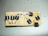
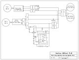
Here is the schematic of the ABCool 4.0.2:
I used a 1A rated diode at the relay, three pole connectors throughout (one pole unused in two of them), and slightly different velcro straps than in the fist unit. It took about three hours to put together this time.
This information may be used entirely at your own risk.
There is always a way if there is no other way!
Well, the darn thing did not sell!
So much for my attempt to turn a lemon into lemonade...HAHA!
This information may be used entirely at your own risk.
There is always a way if there is no other way!
I'm sorry to hear that... I can only speak for myself.
My reasons to not buy were:
- My bike is "still in warranty";
- My knowledge about electronics is very low and I'm afraid doing something wrong in installation.
My experience and concerns about cooling down the battery tell me that your device is a great help. It could be replaced by a firmware patch that could introduce a specific timer for extra ventilation, but since that will not happen, your device becomes a great option.
I don't understand why people didn't buy it...
Keep on the good working
Same.... My bike is still under warranty... I appreciate the great potential of ABCOOL to extend the battery life, but I can't install it.
Mik, i suppose thats the case with most of us, Warranty.
Thanks for your work!
RaDy
I decided to build an ABCool with diode OR-ing instead of the relay.
BAD IDEA!
I found out the hard way that this produces problems and fried my laptop and maybe my CBA II.
I built this:
(All the diodes shown as Zener diodes are actually Schottki diodes; I couldnot find a proper Schottki diode symbol.)
And it works well, until you connect a CBA II to the M-BMS to find out how the capacity is holding up.
At that instant it destroyed my computer!
More details on ES: https://www.endless-sphere.com/forums/viewtopic.php?f=14&t=13490 and https://www.endless-sphere.com/forums/viewtopic.php?f=14&t=8794&p=200096#p200096
Here you can see the schematic for the M-BMS: http://visforvoltage.org/sites/default/files/Vectux%20M-BMS%20Switch%20Array%202009-05-10.pdf
http://visforvoltage.org/sites/default/files/Vectux%20M-BMS%202009-05-10.pdf
I think I have now figured out what goes wrong. The old ABCool design with a relay instead of diode OR-ing would have prevented the disaster!
For reasons which I do not fully understand the device causes a DC voltage between Earth and each single battery cell tab in the M-BMS!
And as I know now, USB cables are earthed. So when I connected the CBA II to the battery tabs 3 and 4, a 42V DC shock went through the CBA II to my laptop. I don't know yet if it has also fried the CBA II on the way through. I'm a bit apprehensive about plugging it into my last remaining computer to try it out!
The about 40V DC between tabs and Earth occur as soon as the plug of the auxiliary power supply is plugged into a power outlet, even if the outlet is turned off. Turning the power point off disconnects the Active pole, I think. So it must be due to Neutral or Earth making contact.
Unplugging the connector going to the impellers does not change this, the effect happens because of the negative cable from ABCool to stock (charger) electronics. As soon as I connect just the negative pole of the auxiliary power supply to the diode OR-ing cable, the 40V DC appear between tabs and Earth. It does not matter if the auxiliary power supply is connected through the box of diodes and resistors, or straight to the cable with the OR-ing diodes.
This information may be used entirely at your own risk.
There is always a way if there is no other way!
The problem which caused the frying of my laptop seems to have a name: "Ground Loop"
http://en.wikipedia.org/wiki/Ground_loop_%28electricity%29
I won't forget that one...seems to be one of the common pitfalls that they might tell you about when studying electrical engineering!
This information may be used entirely at your own risk.
There is always a way if there is no other way!