Unfortunately the original thread seems to have gotten too long, too many videos and photos, so it crashes Firefox each time I try to post!
That is why I start this new post. The background can be found on VisforVoltage there: http://visforvoltage.org/forum/5821-vectux-now-has-hazard-lights
I am offering the first Hazard Light Kit for sale on ebay and will post detailed instructions in this thread on how to install it or build your own kit. There is much more information at the above mentioned post!
See http://cgi.ebay.com.au/ws/eBayISAPI.dll?ViewItem&item=220485543624&ssPageName=STRK:MESELX:IT for the ebay listing.
It's the same deal as with the ABCool: Money back for one week after receiving the kit, no other warranty whatsoever.
.
This is what it looks like installed:
.
.
The kit consists of a waterproof (DPDT, IP67) switch with color-matched cables soldered to the terminals so that flicking the switch will short both the right and the left turn signal cable to the common, orange cable. The ICM then turns on all indicator lights. There are two different blinking patterns, see this post for details: http://visforvoltage.org/forum/5821-vectux-now-has-hazard-lights#comment-34123
The cables used for the kit are color matched to the cables to which they need to be connected to. This makes it very easy to connect it properly.
You could install it yourself, or print these instructions and ask any auto electrician to install it for you!
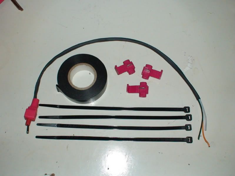
The kit also includes cable ties, quick-connectors (insulation displacing) and some electrical tape.
Tools needed are: 2mm hex key; phillips head screwdriver; scissors; combination pliers.
Time needed for the installation: Under 10 minutes.
.
.
The kit shown in the photos below has black shrink-wrap only on the part nearest the switch. This is so that the installation process can be shown more clearly. Likewise, I used white cable-ties to make the instruction photos so you can see clearly where to install them. The kit for sale (photo above) has black shrink-wrap along most of it's length to protect it. Only the very end of the cables is exposed to allow connection to cables of the same color, using the insulation displacing connectors. The cable ties in the kit are black, and so is the electrical tape to cover up the connectors. It will all blend in much better than in the following photos!
This kit is not meant to be removed again; it can be removed, but it will not be possible to totally hide that it has been there. It will leave some marks where the connectors pierce the cables insulation layer, and you need to remove a small length of the shrink-wrap around the original cables. The outward appearance of the Vectrix will however remain totally unchanged; the switch could be placed under the plastic cover temporarily without removing it (if original looks are desired for some reason).
.
.
Here are the installation steps:
Remove these 2 screws on the top plastic cover on the handlebars:
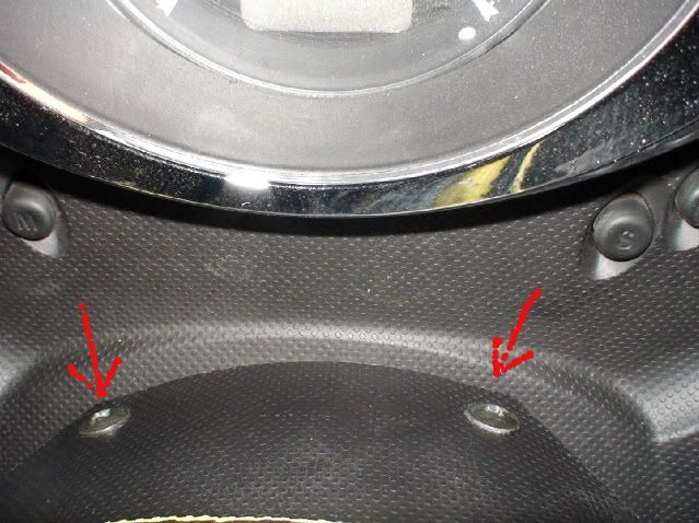
.
Then remove two similar screws from underneath the plastic cover, one on each side:
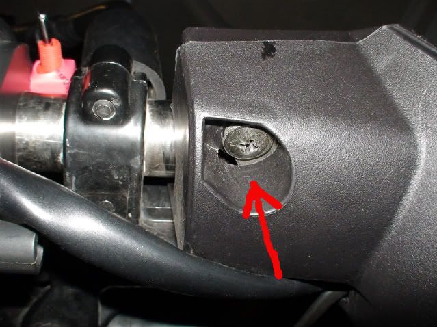
.
Then loosen these 2 hex screws for a few turns, but without taking them out, one on each side, with a 2mm hex key:
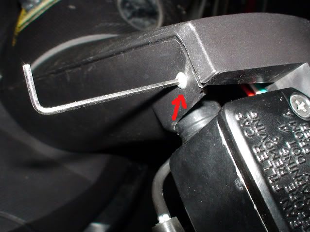
.
Then lift off the top of the black plastic cover carefully.
.
.
Find this connector and push the release button to pull out the part with the cables going to the left handlebar switch cluster. Pull on the plastic, not on the cables:
.
.
Cut open the shrink-wrap cover around the cables for about 5 cm and then cut off the sliced open shrink-wrap. Take care not to cut the cables!
Then identify the orange, grey and green cables (they are located next to each other):
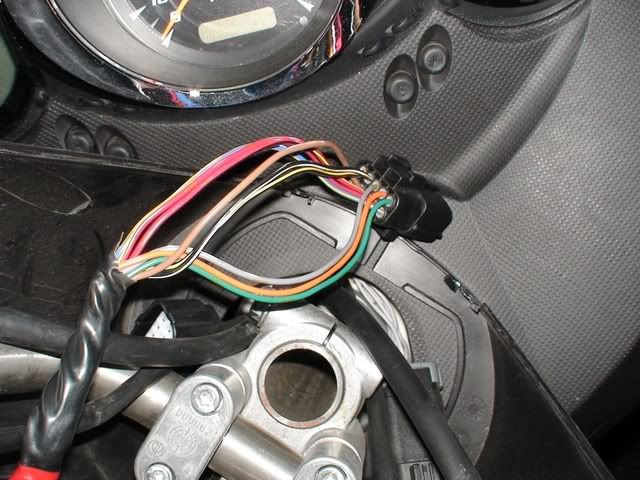
.
Then connect the corresponding colored cables using the insulation displacing connectors. They do not cut the cables; they just slice through the rubbery outside of the cables to make contact with the copper core. You need pliers to squish them together.
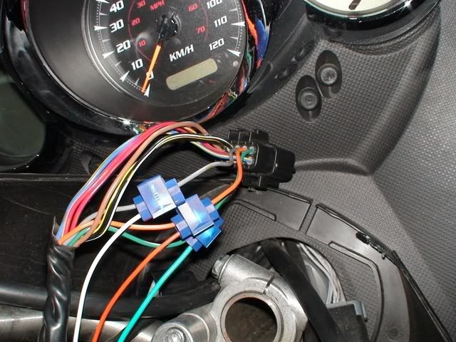
.
To be continued...


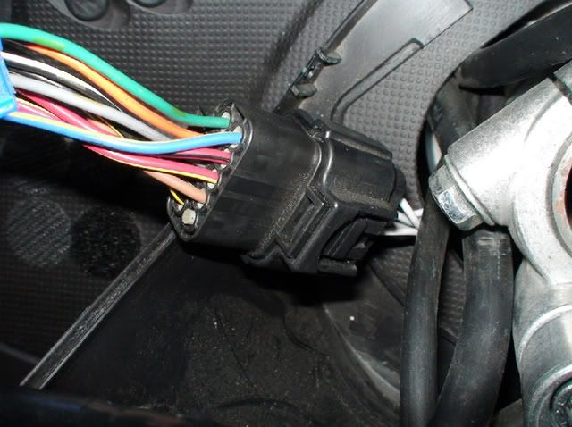


Prior to the cutting of the black shrink-wrap around the original cables you might have to cut one or more of the original cable ties which hold the cable harness to the handlebars. Note where they are, so that you can place the new cable ties in the same places later on, together with the added hazard light cables!
.
Lay the cables along the handlebar and past the brake fluid container. Make sure the cables are not on top of the plastic cover where it will join again with the top part of the cover.
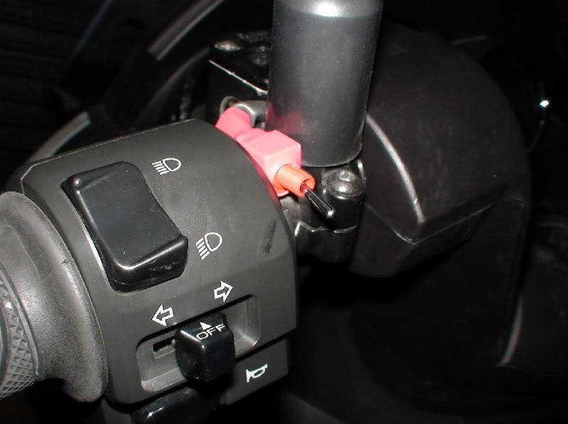
Push the switch into the gap between the mirror and the light-switch-cluster housing.
Then place a cable tie to hold it securely in place.
DO NOT WRAP CABLE TIES AROUND THE BRAKE FLUID HOSES!
This information may be used entirely at your own risk.
There is always a way if there is no other way!
I suggest you try another image server, maybe photobucket server believes that all these successive solicitudes are some kind of ciber-attack and makes firefox to crash.
Test that it works as it should. Turn on the Vectrix; after the boot up sequence flick the Hazard Light Switch to test if the Hazard Lights come on. If it's not working, then give the quick-connectors another squeeze; the blades inside it might not have cut through the insulation to make contact with the copper core of the wires!
Once it is all working as it should, wrap the newly attached quick-connectors up in electrical tape.
Push the connector together until it clicks.
Then place more cable ties to hold the new cables securely together with the original cables.
Avoid any interference with the brake hoses!
Tie the cables down so that the plastic cover can go on again without touching the cables much.
This information may be used entirely at your own risk.
There is always a way if there is no other way!
Once all the cables are tied down and wrapped up, carefully put the black plastic cover back on.
Make sure that the metal squares which are screwed onto the hex screws slide behind the plastic properly and that no cables are getting in the way.
This can be fiddly, but once you have the cover in the right position it will fit well. Do not force it! Working in a well lit environment will help a lot to get the cover back on easily; it's difficult to see any detail of a those black parts if it is not well lit.
Then insert the 4 Phillips-head screws and tighten them gently. Do not over tighten them or you will damage the threading!
If the switch does not sit firmly enough between the mirror and the switch cluster, you may put a drop of hot-melt-glue or a small piece of double-sided sticky tape under it.
And that's it!
You should be able to get two different blinking patterns (ignore all those other extras in the video, that is part of the M-BMS and has nothing to do with the Hazard lights! This video was made with the prototype switch in the hard to reach position):
This information may be used entirely at your own risk.
There is always a way if there is no other way!
Nice
I agree!
But, it did not sell!
So much for my marketing skills! HAHA!
Good I got that out of my system!
This information may be used entirely at your own risk.
There is always a way if there is no other way!
Mik, the problem is the Warranty, not your marketing skills, actually , you without knowing, by posting that you could opem up the Vec and fix things by yourself, have actually helped in the confidence in people of buying a Vectrix, i think its been positive for Vectrix in some ways!
exactly,
I remember saying, in one of my early posts on this forum, that one of the reasons that I decided to buy the V, was my confidence that this community would succeed in repairing, maintaining and upgrading it.
And without Mik in this, it would have been different.
upgrades like hazard lights and cooling devices may seem not important enough (that last one at least not for me, living in "frigid" Belgium), but it's Miks experience and boldness that made me believe.
I would truly understand that he feels 'alone' (at the top) and that he is getting tired and fed up with all the voluntary(!) work.
But he is HOPE for all of us and I would recommendany EV company to find and hire him!
Mik, hold on, the reward will once come to you.
All I can do is try to catch up with the knowledge and experience and in the meanwhile I'll stick around to support anyone who needs it.
And wait for more upgrades :-)
cheers!
"doing nothin = doing nothing wrong" is invalid when the subject is environment
can i use a single switch with two diode? 1n4148? so i can use a standard button with emblem of hazard
Presently, hazards function is integrated inside latest Framuga ICM Versions. you don't need to do hardware mods, just update ICM.
can you explain? how can i activate it if i have the Framuga ICM firmware?
A list of functions.
Version FRA-50CC – Extra functions memoràndum- Hi-low beam indicator in dashboard no longer blinks with low consumption lamps (LED)
- Automatic hazard lights when reversing
- Kill switch and turn signal triggers hazard lights. Turn signal+ reverse triggers hazard lights
- Flash button (for hi beam) no longer turns on hi beam, it is used as “function button”. Functions (CC version):
1) While ridding over 20 km/h, Flash light hold for one beep= top speed limited.
Then when full throttle applied = control cruise enabled.
It activates real CC from ICM to MC. To use this feature you must install MC 1014bCC or 1021CC from the laird box.
Generation of MC firmwares Dugas/MC20XX you need to enable cruise control trough scooterdiag command, look at PDF attached.
Side stand is lit on when CC is on. Regen or brake lever disables CC.
2) With vectrix stopped +Flash light hold 6 beeps= dual hi-lo beam enabled
3) With vectrix stopped +Flash light hold 9 beeps= lo beam off
- Pulse Filter added to side stand signal, which sometimes disables Go while ridding
- Carousel of extra values displayed on left odometer. To enable it, pull left brake lever, and turn on the bike.
Values:
1) AHD - hour amps discharged since last full charge cycle.
2) AHC - hour amps charged during last charge
3) CT – heat-sink temperature of motor controller. Over 60 degrees Celsius better slow down.
4) RAT ratio between kilometres / discharged amps / travelled. Rat over 2.5km every Ah = superb!
>Magic ICM FRA-50CC
All previous functions and:
- MAGIC ICM version stands for magic Box = programmable ICM that controls ESD charge (install configurable ESD firmware V1.2 on charger to enable ICM control).
Configurable values:
CPV constant power phase, set voltage
CPA, "" set amperes
CCV constant current phase, set voltage
CCA "" set amperes
BC battery capacity in Ah. In your case, your battery should hold between 10-15Ah
LC leakage current&co, to my knowledge not implemented (maybe V1,3).
SENDOH values have been saved to ICM
Please help improve that code, suggestions are wellcome!
Thanks....excellent information.