I would like some ideas about how to install a charging / discharging access point to a VX1.
The problem is quite simple for charging-only access: A diode (or two) will prevent any current flowing out of the battery. But this will not allow discharging. Hence it is safe.
But unfortunately, discharging is also needed, although less frequently than charging. I would like to have a very safe option to discharge the battery without having to take the covers off. Removing the seat would be an acceptable amount of work for preparing the discharge.
Here is why I think discharges are sometimes needed:
In hot climates the Vectrix is not very suitable for Summer riding and should rest for the hottest time of the year. The battery will last much longer that way. But unfortunately a lack of deep cycling causes voltage depression in the cells. This is also the reason for the advice to ride to the red battery telltale every so often. If you don't do it, voltage depression develops and the range reduces. Frequent shallow cycling and long rest periods make it worse.
I finally understand now why the discharge graphs of the Vectux all looked similar to these ones:
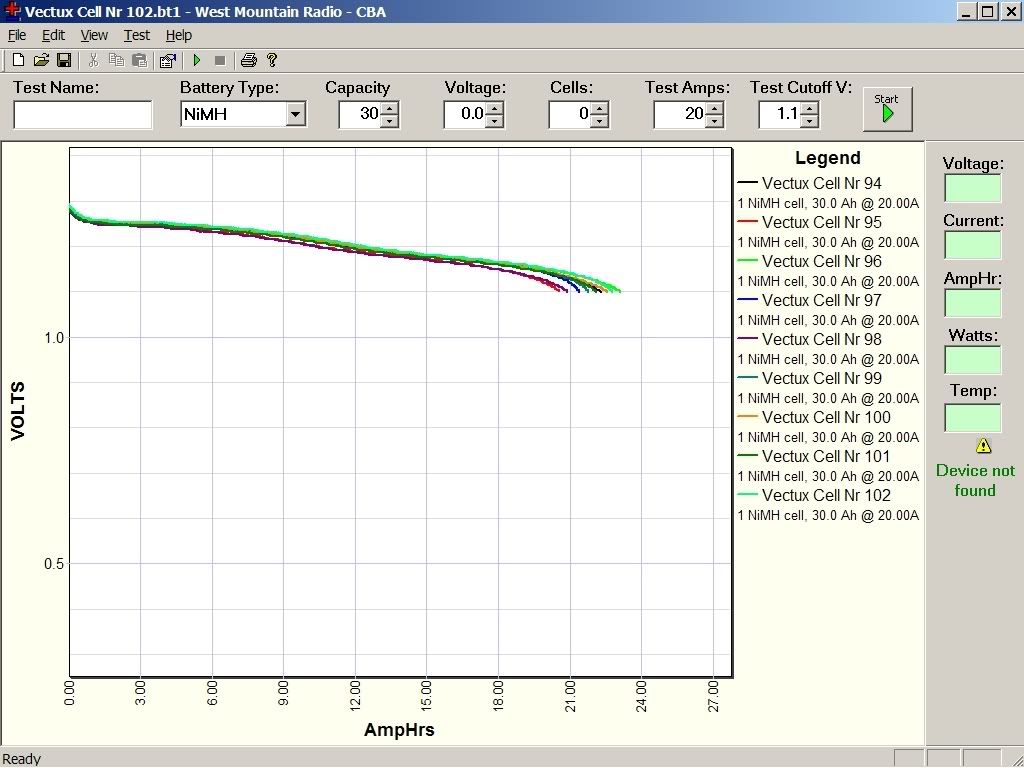
The dip in the curves at around 13Ah is due to the voltage depression of these good cells. They were always discharged to this point only, because the weak cells were empty at that point and a BALPOR occurred. Because of this, the last ~35% of capacity of the good cells was only available in a "voltage depressed" state.
Read this if you want to understand why: Technical Tips for NiCd and NiMH Battery Pack Users — CamLight Systems
In order to have a safe first ride after a prolonged period of inactivity, and indeed to affect a safe exercise cycle for the VX-1 battery at any time (without dangerous crawling around in traffic with a non-roadworthy vehicle) one needs an access point for discharging. But without some safety features, this would also be an access point to electrocution!
Any ideas for how to do this?
How about a diode protected charge port with a relay in parallel to the diode? Apply 12V to the relay coil to close the relay and turn the charge port into a two-way access point! But would that be safe after 30,000km on rough roads, or will the relay get destroyed by the vibrations and become unreliable? What sort of relay would be needed?



Great link, thank you!
Interesting; if you don't do regular full discharge, it says, that it can damage the cells. Edit: I wonder, how is Prius's NiMH being discharged to eliminate voltage depression? AFAIK, it's always between 40%-80% SOC.
I do notice that my Vectrix has grown a voltage depression at around 1.2V/cell; maybe it's time to do a full discharge after the next EQ charge (I want to balance the pack before I do any full discharge).
Hi guys,
heres my recommendations:
nimh cells do not like being reverse charged at high rates (so don't ride the bike to telltale unless you have no other choice).
they, however, don't mind being reversed slowly, at say 1A.
so I would recommend either using:
a) 100 ohm 100W resistor
or
b) a laptop power supply to discharge the pack if you would like to bottom balance.
I too have encountered memory effect.
the voltage depression doesn't harm your cells, and they come back after the next full charge/discharge cycle.
re external tabs:
charge is easy enough, use diodes to prevent the wires outside from being live while unplugged.
discharge is trickier. I would suggest having the load internal, for instance laptop powersupply (or any other SMPS) wired permanently to the battery behind a switch.
discharging individual cells is even more difficult (I have no solution).
Matt
Daily Ride:
2007 Vectrix, modified with 42 x Thundersky 60Ah in July 2010. Done 194'000km
Is this really true? I honestly don't know.
Until now I thought that well designed NiMH cells have a "reserve capacity" to protect them against reverse charging destruction, but that this reserve capacity is a few Ah worth of additional discharge, no matter what current (within reason) is being drawn. As I said, I don't know and may well be wrong about this. I thought that cell capacity imbalance must be less than the reserve discharge capacity of the weakest cells; otherwise these would be reverse charged and get damaged, even at low discharge rates.
You mean connect a load to the 18V DC output of the a SMPS, right? Interesting idea, as SMPS can be powered by DC.
How about using the cooling impellers as a load? The 12V DC SMPS for the ABCool comes to mind - I have a few spares lying about!
4A x 12V = 48W
Say 75% efficiency (probably more) means 60W power draw from the battery.
60W / 120V = 0.5A current draw by running the impellers with the remaining battery power after a long drive, when the battery needs cooling, anyway!
Some experiments may be required to determine at what battery voltage the SMPS would cut out. That might well be the most elegant solution, using the energy for a good purpose.
The ideal device could be something like this:
A SMPS that can run on 125-152VDC and will shut down at about 102VDC; has extremely low standby current (no need for a HV switch then); can produce 4A at 12V output continuously; and is small enough to be mounted somewhere inside the battery safety container, preferably within the cooling air stream which it is powering. In addition to the deep-discharge/voltage depression correction, it would allow autonomous ABCool functionality (during riding and parking away from a power point).
Ride home on a hot summers day, with around 20% left in the hot battery when you get there. Turn on the 12v to the impellers, and let the remaining 6Ah be drained out at a rate of 0.5A for the next 12 hrs, i.e. during the cool night! You end up with a cool, bottom-balanced battery, which will be in peak condition once charged again.
Even more elegant would be a solution that uses the existing VX-1 hardware to achieve the same goal! Everything needed is already there, except for the owner-controlled software command that causes a full EQ-charge, followed by a ride down to 20% remaining capacity (exact number depending on battery health), followed by a looong cooling period - to the point when the battery has just enough ooompf left to allow charging to commence - which it does automatically, of course.....
This information may be used entirely at your own risk.
There is always a way if there is no other way!
Daily Ride:
2007 Vectrix, modified with 42 x Thundersky 60Ah in July 2010. Done 194'000km
What about just leaving the bike turned on and the light turned on? Ok, it will do it more slowly, but it can damage the battery even less.
Can that be done if the battery is not hot? I thought the pre-cooling will only run the impellers when a temperature threshold has been exceeded.
So I guess I'm right that the imbalance (capacity imbalance as well as momentary SOC imbalance) needs to be less than the reserve capacity? If it is not, then the cells are too "bad" for bottom balancing.
By the way, a combination of spontaneous self-discharge and the 7mA constant-on motor controller drain does not cause reversal of the voltage depression effect. I "tried" that....
This information may be used entirely at your own risk.
There is always a way if there is no other way!
Another way would be to ride the bike until the battery is nearly empty,
lift the scooter on the center stand, disable the switch for the stand
and pull the throttle for spinning the !free! rear tyre. If there is no
center stand use a "bike lifter". This should work faster than using the
light or the fans, and using the throttle you have a joice how fast you
discharge the battery. I will try this option soon and report.
Greetings Mike
That will add a lot of km to your odometer!
This information may be used entirely at your own risk.
There is always a way if there is no other way!
Only if the battery temperature is above 24°C and ambient temperature is at least 3°C lower than the battery temperature. Otherwise, it just sits there.
>> That will add a lot of km to your odometer!<<
Yes that could be a problem...
Unfortunately my bike did the BALPOR itself this morning.
There is no Grid when you need one. I was limping home to
save the cells. I reached home with 122 Volt and 22°C
(startet with 19°C) Maybe i was lucky enough, but only
Time will tell.
Greetings Mike
122V isn't that bad. It's GP's recommendation for NiMH cells in a series, that the cut-off Voltage should be set at (n cells - 1)*1,2V = 121V and 22°C, starting from 19°C, is a nice temperature. If you had cell reversal, you'd be seeing 30+°C.
I wonder if that recommended 121v cut-off voltage is under load? I suspect it is.
the lowest no load voltage I have seen, after the red light BalPor has been set is 121v incidentally.
not seeing any high temps is a good sign there was no reversal, agreed.
actually the lower the no load voltage is immediately after a balpor reset the better, its another indicator of how balanced your battery is.
the higher the no load voltage after a balpor has been triggered, the further out of balance your pack is.
Matt
Daily Ride:
2007 Vectrix, modified with 42 x Thundersky 60Ah in July 2010. Done 194'000km
The document doesn't say at what load, so it might be at no load, because the cut-off voltage is different a different loads, so I suspect it's under no load.
I agree with everything else :-) I think he has a well balanced pack.
The guideline for (n-1)x1.2V is probably meant for a C/10 load.
The VX-1 battery voltage drops way lower than 120V under full acceleration - 108V or thereabouts!
See these canbus data:
This is only true if the weak cells have been using only a very small part of their reserve capacity. If they have been over-discharged for more than a few seconds, then the after-discharge voltage will initially be lower.
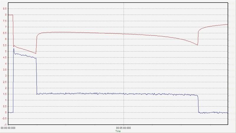
Have a look at the below discharge graph for a 6s NiMH battery (NHW10 Prius Stick; 6.5Ah):
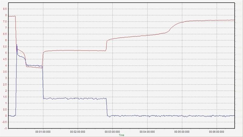
It has a weak cell in it. This weak cell drops to 0Volt during the 100A phase of the test, reducing it to 80A. Because it takes time for the weak cell to recover from the over-discharge (it had not yet reversed), the voltage recovers in two steps.
RED graph: Volt
Blue graph: Ampere x 20
x-axis: minutes
What is shows is that for about 90seconds the voltage after discharge was reduced, because the weak cell had not bounced back up by 1Volt. Once the weak cells are back up to 1.1-1.2Volt, the voltage will indeed be higher with an unbalance battery.
The next graph shows a stick with a weak cell, but because of the short over-discharge time it recovers immediately. The stick voltage is then higher, as antiscab said:
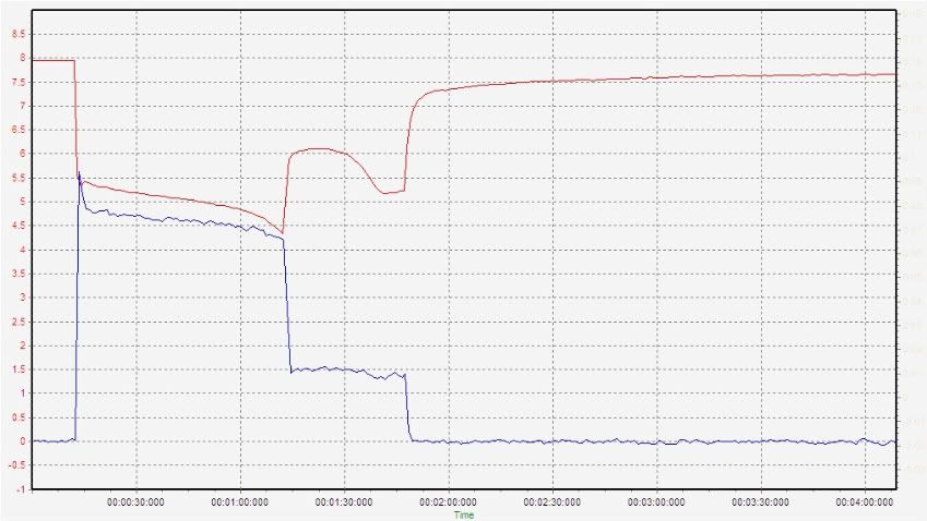
A good stick discharges all cells evenly and therefore the after-discharge voltage is lower, like this one:
The final voltage is not shown, but you might be able to picture the asymtotical approach to less than 7.5V in your minds eye... The final voltage of the sticks with weak cells is around 7.7V.
This information may be used entirely at your own risk.
There is always a way if there is no other way!
these any good for you Mik?
http://www.neutrik.com/fl/en/industry/203_1970434001/powerCON_group.aspx
Maybe! If a very safe connector type could be used, then all the diodes etc are superfluous. But they need to be very tough and foolproof. At the same time they need to be small, so they fit into the very restricted space available.
This information may be used entirely at your own risk.
There is always a way if there is no other way!
the powerCON 32 dimensions on page 6 of this
http://www.neutrik.com/Secure30/getMedia?encoding=ISO-8859-1&client=neutrik&saveAs=true&saveAsName=07_Circular_Connectors_2010_E...\DATA\CLIENT\neutrik\media\downloads\&mediaSavedName=Media_1739534487.pdf&contentType=application/pdf
pretty big chassis connector 40 something mm deep and 32mm square. space under the seat in a corner by the fan for that?
The space limitation is INSIDE the battery safety container.
I do not want any solution that involves any high voltage and high current cables permanently outside of the safety container.
About 20mm protrusion on the inside might be OK if the connector is mounted on the bulging part of the impeller housing just in front of the impellers.
This information may be used entirely at your own risk.
There is always a way if there is no other way!
Looks to me like the powerCON 32 panel mount might fit the the space currently occupied by the 3 pin fan plug. There seem to be a few alternative positions for the fan plug.
I have emailed the Oz distributor for price and availability. I'll let you know what I get back