Re: How to "improve" a NiMH Vectrix battery before it ...
Thanks The Laird!
That looks like an interesting design!
Could it possibly be built using an LM324 op-amp? If yes, then no 30V supply would be needed. I think a 12V DC supply will be needed for most designs (to power the impellers), so it would be convenient to use an op-amp that can "run" on 12V.
This information may be used entirely at your own risk.
Re: How to "improve" a NiMH Vectrix battery before it ...
Hi Mik,
The 081 op-amp will run very successfully on 12volts. The problem is that it's output voltage will range between about 3 volts and 9volts (with a 12volt supply). Op-amps do not (generally) have an output which reaches supply levels. There is then the difficulty of powering the output relay. The relay circuit as drawn will need a relay of 12volts and maybe a few resistor changes. The two 2.7Megohm resistors, in the comparator, would need to be replaced with 1.0 Megohm resistors.
The latching circuit will also need one or two resistor changes, but I would need some time to consider that side of things.
Other than the above, The circuit should run correctly. I will give it some further thought.
If you want any other variations, it is easier for me to look them over before you begin buying and building, might also be cheaper? :-)
Best wishes,
The Laird
Thank you very much!
For now I still have to get the first circuit out of my system (the transistor IDeA). I am more than ever convinced that it is quite feasible and am getting close to have a final version (HAHA!) of the schematic. I already have all the parts for it and need to design my first ever PCB for it.
Once I have found out for myself if you are correct with your impression that it is impossible to do it that way, I'll have time to play with the op-amp version you suggest. An op-amp version was what I was expecting in the beginning, anyway, but now I have spent so much time on developing the transistor version that I want to know for certain if it can be made to work. No disrespect meant - and please continue to point out any potential or actual problems with it!
I now have 4 ASSR-1228 opto-darlingtons and will hopefully get around to breadboard test them all to find out if they behave themselves (when compared to each other).
And I will need a battery to connect any prototype to, that will have to come first, too. Next week is the 15-day self-discharge test date for the 10 replacement cells for the battery I recently analysed. Then I need to take apart and rebuild some of the modules. Connection of prototype to a battery is at least a couple of weeks away for me. When I put the battery together I will probably install a centre-tap (and maybe even 17-cell-segment tabs) just in case neither the 2 nor the 3 segment version of the IDeA works.
What I have done over the last few days is simulate power dissipation values for the transistors in the IDeA circuit, to check that they will never get anywhere near their maximum rating. It is looking good, unless I misunderstand something terribly (which is quite possible).
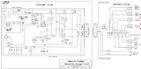
Here is a schematic showing what components will be on the actual PCB and which will be located elsewhere. That will hopefully make it clearer that this circuit is really not all that complicated.
Below is the code (for http://www.falstad.com/circuit/ ) which I used to test the transistor power dissipation and other values of the circuit. It has all those parts stripped away that are not required to test the behaviour of the "Kernel" of the IDeA transistor circuit.
(For some reason the setting for some of the scope traces change when the code is saved. You need to the scope traces for the transistors to show "Vce vs Ic" - at least that's what I found useful to find the maximum power dissipation points.)
This information may be used entirely at your own risk.
Re: How to "improve" a NiMH Vectrix battery before it ...
....
...!
I now have 4 ASSR-1228 opto-darlingtons and will hopefully get around to breadboard test them all to find out if they behave themselves (when compared to each other).
...
......
...
Finally got around to test this: The ASSR opto-Darlingtons passed the test with flying colours!
I think they are ideally suited for this application (not that I really understand how they work, though....)!
I tested 4 ASSR-1228 opto-Darlingtons (that's enough to build 2 IDeA devices), using the 10V testing setup shown earlier in this thread.
The test question was this: How long does it take (with 0.76mA flowing through the ASSR-1228 input side parallel with a 1.2K resistor) for each individual (half-)ASSR-1228 to dimly light the test LED; and how long does it take until the test LED reaches maximum brightness?
The results:
at 760uA; dimly lit / fully lit (in seconds and all measured via visual inspection+wrist-watch by yours truly, a very partial observer...):
1A: 8s/15s
1B: 9s/15s
2A: 8s/15s
2B: 8s/15s
3A: 8s/15s
3B: 8s/15s
4A: 7.5s/14s
4B: 7.5s/14s
I'm very happy with that! Just like I expected. Maybe differences between these individual devices matter at 50kHz - but in the IDeA they are only expected to switch ON a couple of times per year.....and it does not matter much if it takes 1, 2 or 3 seconds longer!
I decided to do just one more comparison to confirm that they are closely "matched" for this application and tested ASSR-1228 4B and 4A again around the minimum threshold current to turn on the test LED.
The results: At 710uA the time to the first dim lighting of the test LED was (followed by eventual full lighting of the test-LED after 1-2min):
4a: 82s
4B: 75s
That result is also just fine with me! The amplification of small voltage imbalances in the Vectrix battery will be so strong around the cutoff point that these minuscule differences are meaningless. It all looks good to me for now!
This information may be used entirely at your own risk.
Re: How to "improve" a NiMH Vectrix battery before it ...
The last schematic above did not include the 1.2k resistors that prevent the opto-darlingtons from switching to closed at very low currents.
I have made up custom symbols for the ASSR-1228 and included them in the new schematic below.
Other changes include how the ICL is operated and how the cooling impellers are being turned on and off. This is all to prevent them from remaining switched on when the Vectux is being switched off. During the next power-up the current draw through the DC/DC converter could be too high for the ICL resistor if the system and the impellers come on together.
The schematic below shows how I hope to disconnect the battery completely each time that the Vectux is being turned off. It will always go into "hibernation" with practically no standby current drain. And one will always have to press the "ICL" momentary switch (and have a working 9V cell in it) to re-awaken it.
This information may be used entirely at your own risk.
Re: How to "improve" a NiMH Vectrix battery before it ...
Hi Mik, hi the Laird,
as I´m out off time because of my job, I´m not writing much these day´s,
but I have to thank both of you for your work on the circuits. Mik I´ll
try to catch up in december when I got more time! But I´ll make my circuit
a little bit smaller than you do, becaus I´ll use it for only for riding,
not for the deep discharge.
Re: How to "improve" a NiMH Vectrix battery before it ...
Your having some great success with the FALSTAD simulator.
It's a great a quick tool to test and share circuits.
I like your LED indicator Find, I haven't worked how to find that one yet.
I have had made some circuits it could find a solution to after 5000 iterations.
But if I moved the ground point it worked.
A current sensors that show the current in the circuit. (Found it just edit the wire and show current and/or voltage ... too easy)
Or just as good a two point voltage meter you can then use with at shunt to show current.
The version is up to 1.5m (your pictures show 1.5k)
And I noticed it has a new export feature that allows a URL link to be made with all the Circuit details hidden into the URL Link
But it doesn't (yet Allow you to copy this into the import window and build the circuit.
You need to use the Browser URL entry.
Also it still comes up in Emailed posts.
Re: How to "improve" a NiMH Vectrix battery before it ...
Your having some great success with the FALSTAD simulator.
It's a great a quick tool to test and share circuits.
...
...
...
Yes, it is a nice tool....it even helped me to "invent" something by myself. All "grown on my own dung-heap", so to say, and therefore possibly complete hogwash. If not, then it is probably a well known circuit (and/or an long outdated one...)!
It's purpose is to delay the closing of a contactor for a few seconds, to allow the pre-charge resistors (ICL) to complete charging the capacitors at a controlled current rate. I'll try it out for real as soon as the capacitor arrives.
This information may be used entirely at your own risk.
There is now a resistor in parallel with the capacitor. This allows the cap to discharge so that the delay function resets itself relatively quickly. Without this, there could be problems if the Vectux is turned off and then on again very soon after.
..
And here the schematic showing how it fits into the IDeA:
This information may be used entirely at your own risk.
It is unlikely that no imbalance will occur when the battery voltage drops to around 0.9V/cell= 91.8V and this will turn the DC/DC converter off when in "Automated Deep Discharge" mode. But I would nevertheless like to have an independent safeguard against further discharge that turns it all off at about 92V.
Any ideas how to do this?
This information may be used entirely at your own risk.
Re: How to "improve" a NiMH Vectrix battery before it ...
Hi Mik, did you ask Deutronic directly if it is possible to change the settings that the converter cut off itself at 92V?
Another solution would be a voltage divider and a schmitt trigger which should be easily adapted to work with the Vectrix´
voltages.
The left circuit has two status LED (green above and red below a selected voltage)
The right one has only a red LED lighting up below a selected voltage.
The second circuit with a better drawing.
They would need a voltage devider or other resistorsetings but would work. Unfortunately I´m still running out of time with my
other project (Testing the GP 78Ah NiMh Blocks for my Fiat PandeE.
Here is one link how to calculate voltage dividers: Voltagedivider-calculatro
We would need the "Spannungsteiler-Rechner No. 2" RL is resistance of the schmitt trigger circuit (which must be measured and/
or calculated first)
Mik to check up the latest shemata, some more Info would be helpful as I had problems to recognize each of the Pins 1-22 and
still not sure what the blocks on the left side of the PCB board ar for (The poti´s (adj. resistor) and the transistors of
the "kernel"-circuit?
Re: How to "improve" a NiMH Vectrix battery before it ...
Hi Mik, did you ask Deutronic directly if it is possible to change the settings that the converter cut off itself at 92V?
I did, but they would need at least 50-200 orders to make it worth their while.
Another solution would be a voltage divider and a schmitt trigger which should be easily adapted to work with the Vectrix´
voltages.
The left circuit has two status LED (green above and red below a selected voltage)
The right one has only a red LED lighting up below a selected voltage.
I have not been able to get a simulation of that circuit happening, but have not tried very hard.
Mik to check up the latest shemata, some more Info would be helpful as I had problems to recognize each of the Pins 1-22 and
still not sure what the blocks on the left side of the PCB board ar for (The poti´s (adj. resistor) and the transistors of
the "kernel"-circuit?
I'm working on it. Need to make "custom components" to accurately represent the SMT transistors I have, as well as other components.
This information may be used entirely at your own risk.
Re: How to "improve" a NiMH Vectrix battery before it ...
Hi Mik,
did you get any further with the circuit? I spend a lot of time with the 78Ah NiMH´s
for my Panda, so I got stuck a bit. Finaly I decidet to make the circuit only for
showing the inbalance during the ride. To equalize the cells will be very tricky.
below you see one module with 10 cells at two dischargetests.
The black test was stopped at 50 Ah because one cell was empty. The other nine where
discharged in a seperate test which showed they had 20 Ah left. After a full charge
I discharged the 10 cells and they had become equal (red test).
on other tests I had cells with only 50% left when the other 9 cells had 90% charge.
To balance such cells would mean to overcharge between 30 and 50% of the capacity.
So I´m looking for a possibility for single cell charging which is small enought to
be left in the battery and cheap enough to be build. Something like the cutoff-modules
attached on Lifpo4-cells. In this case not for chargecutoff but to charge each cell with
0,1-0,5 A to a certain voltage level...
Re: How to "improve" a NiMH Vectrix battery before it ...
Hi Mik,
did you get any further with the circuit? I spend a lot of time
with the 78Ah NiMH´s
for my Panda, so I got stuck a bit. Finaly I decidet to make the
circuit only for
showing the inbalance during the ride.
I have been busy with my newly acquired Prius Scanner, fixing
mine and other people's NHW10's. The Vectux is taking a back seat at the
moment. All I have managed to do is put it on the main stand and
finally move it under cover. Am getting the Bathot + temperature
+ battery warning telltale due to false temp sensor readings.
Will have to take off the M-BMS and see if the problem
disappears. It's a little moist here at the moment....and if it
occasionally stops raining, it quickly gets too hot to ride. I can't be bothered to take the thing apart again!
But the DC/DC converter for the IDeA is in the mail and the IDeA keeps on
fermenting on low heat in the back of my mind.
.
The "Special Freddy NHW10 EQ Charger 15.0" is going to be completed
as soon as the last part arrives, a 6VDC 4PDT relay. The charger
itself is ready and working quite reliably, but the "Battery
Side" part needs to be installed so that I can do a Prius EQ
charge without any hassle, like removing the back seat, opening
the battery, exposing dangerous parts etc etc.
With the Techno Scanner I can now measure all sorts of things in
real time, like 20 battery module voltages, current, pack
voltage, 9 different temperatures in the pack, delta-SOC, SOC and
anything else that was designed into the car. Hundreds of items,
most of them displayed only in Japanese. A great toy and great
insights into a good NiMH BMS! And it is so much more comfortable
to drive an airconditioned Prius with roof over my head than a
Vectrix. So it may be quite a while before I get to work on it
again.
.
.
To equalize the cells will be very tricky.
below you see one module with 10 cells at two dischargetests.
The black test was stopped at 50 Ah because one cell was empty.
The other nine where
discharged in a seperate test which showed they had 20 Ah left.
After a full charge
I discharged the 10 cells and they had become equal (red test).
on other tests I had cells with only 50% left when the other 9
cells had 90% charge.
To balance such cells would mean to overcharge between 30 and 50%
of the capacity.
So I´m looking for a possibility for single cell charging which
is small enought to
be left in the battery and cheap enough to be build. Something
like the cutoff-modules
attached on Lifpo4-cells. In this case not for chargecutoff but
to charge each cell with
0,1-0,5 A to a certain voltage level...
Greetings Mike
Equalising the cells in the battery will be tricky, indeed. I
would try to replace the worst ones, and concentrate the
moderately damaged ones into one easily accessible part of the
battery. In the module shown above it is an increased self-
discharge rate in the weak cell that is causing the trouble.
If it is not too severe, and if you do not need the entire
battery capacity, it might possible to use the battery "as is". If
you can limit the DOD to 50% of the battery capacity, the weak
cell would end up operating between 10%SOC and 60%SOC while the
best cells operate between 40%SOC and 90%SOC. That would keep all
cells reasonably happy - the SDC is much higher at higher SOC, so
the imbalance might stabilise. The imbalance detection circuit
could warn you when a cell eventually reverses. Depending on the
overall battery SOC at which this occurs you could then do a
partial EQ charge, to bring the weakest cells back to within 30%
delta-SOC of the better cells. It would be really easy to do a
"no damage EQ charge" if the weak cells are arrenged into a
coninuous sub-string anywhere in the battery that is easy to get to,
or that has permanent tab cables installed. You just top up
the weaker cells once the imbalance detector goes off,
or better, just before it goes off! That would inflict little damage
upon the good cells if done slowly and with active cooling.
It all depends on if you can live with using only half
your battery capacity most of the time.
How many cells are in your Panda?
.
.
Oh, there is an important question I have about the IDeA:
What level of vibration resistance and shock resistance would be
appropriate for the relays used in a Vectrix scooter?
The only relay in the current IDeA design which could cause a
critical malfunction (due to undesired opening while driving over
bumps) would be RLY2.
RLY2 is normally open; when it's coil is energised with 12V DC
(by turning the key ON or if the "Deep Discharge/Timer Switch" is
closed after powering up) then it will connect the 12.5VDC/DC
converter to the main battery. The DC/DC converter then powers
the Contactor and closes the 102s battery string. If the relay
were to open due to vibration/bumps/shock, the DC/DC converter would
stop providing 12V to the contactor and the power supply would get
disrupted suddenly, causing loss of motor power while in traffic.
Some relays mention in their data sheets how many "g" they can handle,
sometimes for energised vs. non-energised state etc.
What is the appropriate shock and vibration rating to be used for a critically important electric scooter part?
This information may be used entirely at your own risk.
Re: How to "improve" a NiMH Vectrix battery before it ...
It's a little moist here at the moment....and if it
occasionally stops raining, it quickly gets too hot to ride. I can't be bothered to take the thing apart again!
But the DC/DC converter for the IDeA is in the mail and the IDeA keeps on
fermenting on low heat in the back of my mind.
I hope you are not in the area with the heavy raining and the flood?!
I switched most energy to the Panda-Project, as the car can be used
much earlier than the scooter and has far less problems with moisture
as the batteries/chargers are stored where the backseat and trunk are.
curently there are 14x6V 110Ah lead-acid(gel) batteries used. As they
are rather old I can only use about 50 AH giving me a range between 25
and 35 km. So I looked for theese used NiMH modules... each pair of
the batteries is attached as 12 volt module to a simple IU charger.
I plan to replace them with the NiMHs.
...would try to replace the worst ones...
...It all depends on if you can live with using only half
your battery capacity most of the time...
That is no option for me. The modules should be able to deliver
between 65 and 70 AH if needed. normaly I´ll use only 50% of the
capacity. I´ll try to find out how fast they loose their charge
(the cells with faster selfdischarge are marked). And with another
version of the IDEA (with temp-monitoring) I should be able to
see if one module needs a refresh. There will be a problem if I
have to change a cell, because the black plastic-spacers between
the cells are old and weak and begin to brake, so it will tricky
to change a cell without opening the metal-ribons.
...How many cells are in your Panda?...
Now 14 Lead Acid, 84V Systemvoltage 50-60 AH usable charge.
Planed 14 NiMH modules with 84V and 130-140 AH. 7 segments
with 12 volt because of the 7-charger-infrastructure. This
means that either there will be 2 batteries with 7 modules
each and 2x 7 chargers disconneted during charge or one battery
with 7x two modules parallel connected. With my charging current
it would be able to charge them parrallel (10 hour to full) but
it will still need a good thermal sensoring. That would be a
better solution than to have 14 chargers. I don´t plan to
install a 84v Charger, because curent infrastructure it´s
easier to do EQ charges.
...Oh, there is an important question I have about the IDeA:
What level of vibration resistance and shock resistance would be
appropriate for the relays used in a Vectrix scooter?
What is the appropriate shock and vibration rating to be used for a critically important electric scooter part?
I´m sorry I´ve no idea. Is it possible to us only solidstate-relais
instead of electro-mechanic ones? would a thyristor be a solition
for the connection between MC and battery?
Re: How to "improve" a NiMH Vectrix battery before it ...
Hi.
What do you guys think about using a few of those "Lipo Battery Low Voltage LED Tester Meter 1S-8S Buzzer Alarm Indicator" sold on Ebay 3 USD including shipment?
At the moment my plan is to buy six of those (search for "1-8s" on Ebay) to monitor all cells, three by three.
(a cut and paste)
Product Feature:
Use for 1-8s Lipl/Li-ion/LiMn/Li-Fe
Voltage detection pricision: 0.01V
Unit voltage display range: 0.5V-4.5V
Total voltage display range: 0.5V-36V
1S test mode voltage range: 4v-15v
Low voltage alarm mode for 2-8S
Alarm set value range: OFF-2.7V-3.8V
When the voltage is below the set value,it will buzzer with red LED light,pre-set value 3.3V.
Push key which can change the voltage settings and save.
I plan to use three Ethernet patch-cables for each battery-box because it's cheap and available.
Those modules fits in to a old IDE hard drive cable.
Together with 30pcs of ring terminals and 30pcs of 3A car fuses (spade fuses?) it would be possible to find week cells both visual and audibly during riding.
Any thoughts ?
This solution would cost about 50 USD and some work effort.
Re: How to "improve" a NiMH Vectrix battery before it ...
I plan to use three Ethernet patch-cables for each battery-box because it's cheap and available.
Those modules fits in to a old IDE hard drive cable.
Together with 30pcs of ring terminals and 30pcs of 3A car fuses (spade fuses?) it would be possible to find week cells both visual and audibly during riding.
be aware the car fuses are generally only rated up to 32vdc.
above this, when the fuse blows an arc is formed, resulting in the fuse burning as well as the circuit not being broken
given the small wire you are using, that may not be an issue, as when the insulation burns away under a fault condition, the copper oxidizes rapidly leading to high resistance.
I would probably use a lower fuse current if using car fuses, more like 0.5A
other than that, not a bad idea
Matt
Daily Ride:
2007 Vectrix, modified with 42 x Thundersky 60Ah in July 2010. Done 194'000km
Re: How to "improve" a NiMH Vectrix battery before it ...
Ahem.....I never got around to build the complex IDeA (Imbalance Detector Apparatus) and by now I am having a hard time even understanding the schematics.
However, the principle of splitting the pack into three equal segments is valid and proven on the workbench in a few experiments with Vectrix NiMH batteries.
The tricky bit is related to comparing three voltages and then making decisions based on the voltage comparison and then start actions based on the decisions. So I decided to use my brain for that purpose instead of an electronic gizmo.
All the IDeA needs is three voltmeters on the instrument panel and a switch to turn them all off when not needed, to stop the <7mA power drain caused by them. All water proof, of course. And a pair of eyes and a brain. It will not be fully automatic, but very simple and effective.
It will cost about AU180.- for the voltmeters and will allow me to see if there is a reversing cell anywhere in the battery during riding, charging or discharging on the centre stand with the cooling impellers and/or MC and/or headlights on.

Thanks The Laird!
That looks like an interesting design!
Could it possibly be built using an LM324 op-amp? If yes, then no 30V supply would be needed. I think a 12V DC supply will be needed for most designs (to power the impellers), so it would be convenient to use an op-amp that can "run" on 12V.
This information may be used entirely at your own risk.
There is always a way if there is no other way!
Hi Mik,
The 081 op-amp will run very successfully on 12volts. The problem is that it's output voltage will range between about 3 volts and 9volts (with a 12volt supply). Op-amps do not (generally) have an output which reaches supply levels. There is then the difficulty of powering the output relay. The relay circuit as drawn will need a relay of 12volts and maybe a few resistor changes. The two 2.7Megohm resistors, in the comparator, would need to be replaced with 1.0 Megohm resistors.
The latching circuit will also need one or two resistor changes, but I would need some time to consider that side of things.
Other than the above, The circuit should run correctly. I will give it some further thought.
If you want any other variations, it is easier for me to look them over before you begin buying and building, might also be cheaper? :-)
Best wishes,
The Laird
Thank you very much!
For now I still have to get the first circuit out of my system (the transistor IDeA). I am more than ever convinced that it is quite feasible and am getting close to have a final version (HAHA!) of the schematic. I already have all the parts for it and need to design my first ever PCB for it.
Once I have found out for myself if you are correct with your impression that it is impossible to do it that way, I'll have time to play with the op-amp version you suggest. An op-amp version was what I was expecting in the beginning, anyway, but now I have spent so much time on developing the transistor version that I want to know for certain if it can be made to work. No disrespect meant - and please continue to point out any potential or actual problems with it!
I now have 4 ASSR-1228 opto-darlingtons and will hopefully get around to breadboard test them all to find out if they behave themselves (when compared to each other).
And I will need a battery to connect any prototype to, that will have to come first, too. Next week is the 15-day self-discharge test date for the 10 replacement cells for the battery I recently analysed. Then I need to take apart and rebuild some of the modules. Connection of prototype to a battery is at least a couple of weeks away for me. When I put the battery together I will probably install a centre-tap (and maybe even 17-cell-segment tabs) just in case neither the 2 nor the 3 segment version of the IDeA works.
What I have done over the last few days is simulate power dissipation values for the transistors in the IDeA circuit, to check that they will never get anywhere near their maximum rating. It is looking good, unless I misunderstand something terribly (which is quite possible).
Here is a schematic showing what components will be on the actual PCB and which will be located elsewhere. That will hopefully make it clearer that this circuit is really not all that complicated.
Below is the code (for http://www.falstad.com/circuit/ ) which I used to test the transistor power dissipation and other values of the circuit. It has all those parts stripped away that are not required to test the behaviour of the "Kernel" of the IDeA transistor circuit.
(For some reason the setting for some of the scope traces change when the code is saved. You need to the scope traces for the transistors to show "Vce vs Ic" - at least that's what I found useful to find the maximum power dissipation points.)
This information may be used entirely at your own risk.
There is always a way if there is no other way!
Finally got around to test this: The ASSR opto-Darlingtons passed the test with flying colours!
I think they are ideally suited for this application (not that I really understand how they work, though....)!
I tested 4 ASSR-1228 opto-Darlingtons (that's enough to build 2 IDeA devices), using the 10V testing setup shown earlier in this thread.
The test question was this: How long does it take (with 0.76mA flowing through the ASSR-1228 input side parallel with a 1.2K resistor) for each individual (half-)ASSR-1228 to dimly light the test LED; and how long does it take until the test LED reaches maximum brightness?
The results:
at 760uA; dimly lit / fully lit (in seconds and all measured via visual inspection+wrist-watch by yours truly, a very partial observer...):
1A: 8s/15s
1B: 9s/15s
2A: 8s/15s
2B: 8s/15s
3A: 8s/15s
3B: 8s/15s
4A: 7.5s/14s
4B: 7.5s/14s
I'm very happy with that! Just like I expected. Maybe differences between these individual devices matter at 50kHz - but in the IDeA they are only expected to switch ON a couple of times per year.....and it does not matter much if it takes 1, 2 or 3 seconds longer!
I decided to do just one more comparison to confirm that they are closely "matched" for this application and tested ASSR-1228 4B and 4A again around the minimum threshold current to turn on the test LED.
The results: At 710uA the time to the first dim lighting of the test LED was (followed by eventual full lighting of the test-LED after 1-2min):
4a: 82s
4B: 75s
That result is also just fine with me! The amplification of small voltage imbalances in the Vectrix battery will be so strong around the cutoff point that these minuscule differences are meaningless. It all looks good to me for now!
This information may be used entirely at your own risk.
There is always a way if there is no other way!
The last schematic above did not include the 1.2k resistors that prevent the opto-darlingtons from switching to closed at very low currents.
I have made up custom symbols for the ASSR-1228 and included them in the new schematic below.
Other changes include how the ICL is operated and how the cooling impellers are being turned on and off. This is all to prevent them from remaining switched on when the Vectux is being switched off. During the next power-up the current draw through the DC/DC converter could be too high for the ICL resistor if the system and the impellers come on together.
The schematic below shows how I hope to disconnect the battery completely each time that the Vectux is being turned off. It will always go into "hibernation" with practically no standby current drain. And one will always have to press the "ICL" momentary switch (and have a working 9V cell in it) to re-awaken it.
This information may be used entirely at your own risk.
There is always a way if there is no other way!
Hi Mik, hi the Laird,
as I´m out off time because of my job, I´m not writing much these day´s,
but I have to thank both of you for your work on the circuits. Mik I´ll
try to catch up in december when I got more time! But I´ll make my circuit
a little bit smaller than you do, becaus I´ll use it for only for riding,
not for the deep discharge.
Greetings Mike
In the process of trying to design a PCB I have re-arranged the circuit somewhat.
Here is a schematic showing the same "kernel" but arranged differently. The peripheral parts have also changed a bit and are probably not final.
Next is the simulation I used to check the schematic is correct:
And finally the code for the simulation applet:
This information may be used entirely at your own risk.
There is always a way if there is no other way!
Your having some great success with the FALSTAD simulator.
It's a great a quick tool to test and share circuits.
I like your LED indicator Find, I haven't worked how to find that one yet.
I have had made some circuits it could find a solution to after 5000 iterations.
But if I moved the ground point it worked.
A current sensors that show the current in the circuit. (Found it just edit the wire and show current and/or voltage ... too easy)
Or just as good a two point voltage meter you can then use with at shunt to show current.
The version is up to 1.5m (your pictures show 1.5k)
And I noticed it has a new export feature that allows a URL link to be made with all the Circuit details hidden into the URL Link
But it doesn't (yet Allow you to copy this into the import window and build the circuit.
You need to use the Browser URL entry.
Also it still comes up in Emailed posts.
Test Info : Your Circuit as a link - Open in New Tab to launch Simulator
That's because it does not exist, yet!
I'll have to work out how you created that nifty link to the working circuit - very nice! No time right now...
This information may be used entirely at your own risk.
There is always a way if there is no other way!
Playing around with ExpressPCB now, here is a preliminary result:
This information may be used entirely at your own risk.
There is always a way if there is no other way!
Yes, it is a nice tool....it even helped me to "invent" something by myself. All "grown on my own dung-heap", so to say, and therefore possibly complete hogwash. If not, then it is probably a well known circuit (and/or an long outdated one...)!
Anyway, here it is:
http://www.falstad.com/circuit/#%24+1+0.0010+9.78399845368213+42+5.0+50%0A178+672+368+672+416+0+1+0.2+8.881784197001253E-18+0.05...
It's purpose is to delay the closing of a contactor for a few seconds, to allow the pre-charge resistors (ICL) to complete charging the capacitors at a controlled current rate. I'll try it out for real as soon as the capacitor arrives.
This information may be used entirely at your own risk.
There is always a way if there is no other way!
Here is a little improvement to the contactor-delay circuit:
http://www.falstad.com/circuit/#%24+1+0.0010+9.78399845368213+42+5.0+50%0A178+672+368+672+416+0+1+0.2+6.1235740190905994E-18+0.0...
There is now a resistor in parallel with the capacitor. This allows the cap to discharge so that the delay function resets itself relatively quickly. Without this, there could be problems if the Vectux is turned off and then on again very soon after.
..
And here the schematic showing how it fits into the IDeA:
This information may be used entirely at your own risk.
There is always a way if there is no other way!
And here the latest PCB design for the IDeA:
It probably still has errors in it and needs thorough checking before I make one (or have one made).
If anyone wants to help with double-checking the PCB design, send me a PM and I can send the ExpressPCB file to make it easier.
This information may be used entirely at your own risk.
There is always a way if there is no other way!
Does anyone have a good idea how to integrate a cutoff-voltage for the DC/DC converter?
The DVC75 which I intend to use http://deutronic.com/fahrzeugwandler/75-watt-pot-getr_data_de.pdf works with input voltages from 56V-154VDC.
It is unlikely that no imbalance will occur when the battery voltage drops to around 0.9V/cell= 91.8V and this will turn the DC/DC converter off when in "Automated Deep Discharge" mode. But I would nevertheless like to have an independent safeguard against further discharge that turns it all off at about 92V.
Any ideas how to do this?
This information may be used entirely at your own risk.
There is always a way if there is no other way!
Hi Mik, did you ask Deutronic directly if it is possible to change the settings that the converter cut off itself at 92V?
Another solution would be a voltage divider and a schmitt trigger which should be easily adapted to work with the Vectrix´
voltages.
The left circuit has two status LED (green above and red below a selected voltage)
The right one has only a red LED lighting up below a selected voltage.
The second circuit with a better drawing.
They would need a voltage devider or other resistorsetings but would work. Unfortunately I´m still running out of time with my
other project (Testing the GP 78Ah NiMh Blocks for my Fiat PandeE.
Here is one link how to calculate voltage dividers: Voltagedivider-calculatro
We would need the "Spannungsteiler-Rechner No. 2" RL is resistance of the schmitt trigger circuit (which must be measured and/
or calculated first)
Mik to check up the latest shemata, some more Info would be helpful as I had problems to recognize each of the Pins 1-22 and
still not sure what the blocks on the left side of the PCB board ar for (The poti´s (adj. resistor) and the transistors of
the "kernel"-circuit?
greeetings Mike
I did, but they would need at least 50-200 orders to make it worth their while.
I have not been able to get a simulation of that circuit happening, but have not tried very hard.
I'm working on it. Need to make "custom components" to accurately represent the SMT transistors I have, as well as other components.
This information may be used entirely at your own risk.
There is always a way if there is no other way!
Hi Mik,
did you get any further with the circuit? I spend a lot of time with the 78Ah NiMH´s
for my Panda, so I got stuck a bit. Finaly I decidet to make the circuit only for
showing the inbalance during the ride. To equalize the cells will be very tricky.
below you see one module with 10 cells at two dischargetests.
The black test was stopped at 50 Ah because one cell was empty. The other nine where
discharged in a seperate test which showed they had 20 Ah left. After a full charge
I discharged the 10 cells and they had become equal (red test).
on other tests I had cells with only 50% left when the other 9 cells had 90% charge.
To balance such cells would mean to overcharge between 30 and 50% of the capacity.
So I´m looking for a possibility for single cell charging which is small enought to
be left in the battery and cheap enough to be build. Something like the cutoff-modules
attached on Lifpo4-cells. In this case not for chargecutoff but to charge each cell with
0,1-0,5 A to a certain voltage level...
Greetings Mike
I have been busy with my newly acquired Prius Scanner, fixing
mine and other people's NHW10's. The Vectux is taking a back seat at the
moment. All I have managed to do is put it on the main stand and
finally move it under cover. Am getting the Bathot + temperature
+ battery warning telltale due to false temp sensor readings.
Will have to take off the M-BMS and see if the problem
disappears. It's a little moist here at the moment....and if it
occasionally stops raining, it quickly gets too hot to ride. I can't be bothered to take the thing apart again!
But the DC/DC converter for the IDeA is in the mail and the IDeA keeps on
fermenting on low heat in the back of my mind.
.
The "Special Freddy NHW10 EQ Charger 15.0" is going to be completed
as soon as the last part arrives, a 6VDC 4PDT relay. The charger
itself is ready and working quite reliably, but the "Battery
Side" part needs to be installed so that I can do a Prius EQ
charge without any hassle, like removing the back seat, opening
the battery, exposing dangerous parts etc etc.
With the Techno Scanner I can now measure all sorts of things in
real time, like 20 battery module voltages, current, pack
voltage, 9 different temperatures in the pack, delta-SOC, SOC and
anything else that was designed into the car. Hundreds of items,
most of them displayed only in Japanese. A great toy and great
insights into a good NiMH BMS! And it is so much more comfortable
to drive an airconditioned Prius with roof over my head than a
Vectrix. So it may be quite a while before I get to work on it
again.
.
.
Equalising the cells in the battery will be tricky, indeed. I
would try to replace the worst ones, and concentrate the
moderately damaged ones into one easily accessible part of the
battery. In the module shown above it is an increased self-
discharge rate in the weak cell that is causing the trouble.
If it is not too severe, and if you do not need the entire
battery capacity, it might possible to use the battery "as is". If
you can limit the DOD to 50% of the battery capacity, the weak
cell would end up operating between 10%SOC and 60%SOC while the
best cells operate between 40%SOC and 90%SOC. That would keep all
cells reasonably happy - the SDC is much higher at higher SOC, so
the imbalance might stabilise. The imbalance detection circuit
could warn you when a cell eventually reverses. Depending on the
overall battery SOC at which this occurs you could then do a
partial EQ charge, to bring the weakest cells back to within 30%
delta-SOC of the better cells. It would be really easy to do a
"no damage EQ charge" if the weak cells are arrenged into a
coninuous sub-string anywhere in the battery that is easy to get to,
or that has permanent tab cables installed. You just top up
the weaker cells once the imbalance detector goes off,
or better, just before it goes off! That would inflict little damage
upon the good cells if done slowly and with active cooling.
It all depends on if you can live with using only half
your battery capacity most of the time.
How many cells are in your Panda?
.
.
Oh, there is an important question I have about the IDeA:
What level of vibration resistance and shock resistance would be
appropriate for the relays used in a Vectrix scooter?
The only relay in the current IDeA design which could cause a
critical malfunction (due to undesired opening while driving over
bumps) would be RLY2.
RLY2 is normally open; when it's coil is energised with 12V DC
(by turning the key ON or if the "Deep Discharge/Timer Switch" is
closed after powering up) then it will connect the 12.5VDC/DC
converter to the main battery. The DC/DC converter then powers
the Contactor and closes the 102s battery string. If the relay
were to open due to vibration/bumps/shock, the DC/DC converter would
stop providing 12V to the contactor and the power supply would get
disrupted suddenly, causing loss of motor power while in traffic.
Some relays mention in their data sheets how many "g" they can handle,
sometimes for energised vs. non-energised state etc.
What is the appropriate shock and vibration rating to be used for a critically important electric scooter part?
This information may be used entirely at your own risk.
There is always a way if there is no other way!
I hope you are not in the area with the heavy raining and the flood?!
I switched most energy to the Panda-Project, as the car can be used
much earlier than the scooter and has far less problems with moisture
as the batteries/chargers are stored where the backseat and trunk are.
curently there are 14x6V 110Ah lead-acid(gel) batteries used. As they
are rather old I can only use about 50 AH giving me a range between 25
and 35 km. So I looked for theese used NiMH modules... each pair of
the batteries is attached as 12 volt module to a simple IU charger.
I plan to replace them with the NiMHs.
That is no option for me. The modules should be able to deliver
between 65 and 70 AH if needed. normaly I´ll use only 50% of the
capacity. I´ll try to find out how fast they loose their charge
(the cells with faster selfdischarge are marked). And with another
version of the IDEA (with temp-monitoring) I should be able to
see if one module needs a refresh. There will be a problem if I
have to change a cell, because the black plastic-spacers between
the cells are old and weak and begin to brake, so it will tricky
to change a cell without opening the metal-ribons.
Now 14 Lead Acid, 84V Systemvoltage 50-60 AH usable charge.
Planed 14 NiMH modules with 84V and 130-140 AH. 7 segments
with 12 volt because of the 7-charger-infrastructure. This
means that either there will be 2 batteries with 7 modules
each and 2x 7 chargers disconneted during charge or one battery
with 7x two modules parallel connected. With my charging current
it would be able to charge them parrallel (10 hour to full) but
it will still need a good thermal sensoring. That would be a
better solution than to have 14 chargers. I don´t plan to
install a 84v Charger, because curent infrastructure it´s
easier to do EQ charges.
I´m sorry I´ve no idea. Is it possible to us only solidstate-relais
instead of electro-mechanic ones? would a thyristor be a solition
for the connection between MC and battery?
gretings Mike
Hi.
What do you guys think about using a few of those "Lipo Battery Low Voltage LED Tester Meter 1S-8S Buzzer Alarm Indicator" sold on Ebay 3 USD including shipment?
At the moment my plan is to buy six of those (search for "1-8s" on Ebay) to monitor all cells, three by three.
(a cut and paste)
Product Feature:
Use for 1-8s Lipl/Li-ion/LiMn/Li-Fe
Voltage detection pricision: 0.01V
Unit voltage display range: 0.5V-4.5V
Total voltage display range: 0.5V-36V
1S test mode voltage range: 4v-15v
Low voltage alarm mode for 2-8S
Alarm set value range: OFF-2.7V-3.8V
When the voltage is below the set value,it will buzzer with red LED light,pre-set value 3.3V.
Push key which can change the voltage settings and save.
I plan to use three Ethernet patch-cables for each battery-box because it's cheap and available.
Those modules fits in to a old IDE hard drive cable.
Together with 30pcs of ring terminals and 30pcs of 3A car fuses (spade fuses?) it would be possible to find week cells both visual and audibly during riding.
Any thoughts ?
This solution would cost about 50 USD and some work effort.
be aware the car fuses are generally only rated up to 32vdc.
above this, when the fuse blows an arc is formed, resulting in the fuse burning as well as the circuit not being broken
given the small wire you are using, that may not be an issue, as when the insulation burns away under a fault condition, the copper oxidizes rapidly leading to high resistance.
I would probably use a lower fuse current if using car fuses, more like 0.5A
other than that, not a bad idea
Matt
Daily Ride:
2007 Vectrix, modified with 42 x Thundersky 60Ah in July 2010. Done 194'000km
Ahem.....I never got around to build the complex IDeA (Imbalance Detector Apparatus) and by now I am having a hard time even understanding the schematics.
However, the principle of splitting the pack into three equal segments is valid and proven on the workbench in a few experiments with Vectrix NiMH batteries.
The tricky bit is related to comparing three voltages and then making decisions based on the voltage comparison and then start actions based on the decisions. So I decided to use my brain for that purpose instead of an electronic gizmo.
All the IDeA needs is three voltmeters on the instrument panel and a switch to turn them all off when not needed, to stop the <7mA power drain caused by them. All water proof, of course. And a pair of eyes and a brain. It will not be fully automatic, but very simple and effective.
It will cost about AU180.- for the voltmeters and will allow me to see if there is a reversing cell anywhere in the battery during riding, charging or discharging on the centre stand with the cooling impellers and/or MC and/or headlights on.
http://www.murata-ps.com/data/meters/dmr20-10-dcm.pdf
Does that make sense?
This information may be used entirely at your own risk.
There is always a way if there is no other way!
Pages