Hi all,
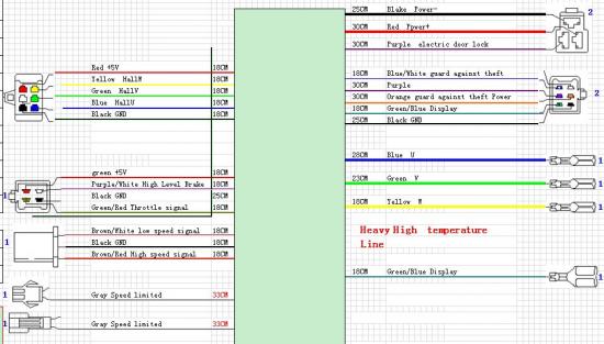
I now managed to receive a wiring scheme for my controller:
I hope some of you can provide feedback to the open questions which come up after I have seen and tried to understand.
The following questions:
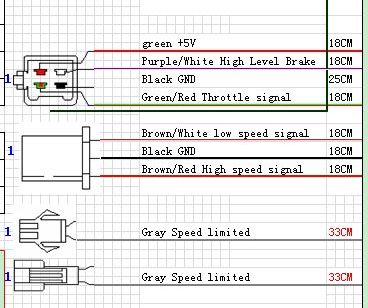
* I already know that connecting the two grey result in lower speed, very low speed----like 15km/h.
but what does the brown/white low speed signal and brown/red high speed signal mean???
maybe you have similar features in other controller.....this connector is open in my case and not connected anywhere....
* does anybody understand what green/blue display means??
* and what does the purple electric door lock do?, how does it work?
Thanks, really curious to hear and read from your feedbacks!
| Attachment | Size |
|---|---|
| 35.62 KB | |
| 31.39 KB |


* I already know that connecting the two grey result in lower speed, very low speed----like 15km/h.
but what does the brown/white low speed signal and brown/red high speed signal mean???
maybe you have similar features in other controller.....this connector is open in my case and not connected anywhere....
* does anybody understand what green/blue display means??
* and what does the purple electric door lock do?, how does it work?
Thanks, really curious to hear and read from your feedbacks!
hi, njordan:
1.there are two solutions for three speed control, one is low speed --PWM output max. to 60%, nomal speed --- max. to 80%, high speed-- max. to 100%. low voltage level effected. Two is 80%, 100%, 120%. just try it.
2. display line mean battery voltage level display
3. door lock must use alarm device, input one low level signal to controller to lock motor.
King Dun.