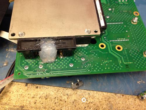
I was made to regret saying 'after 5 years my V will have paid for itself so I can throw it away' when, on the exact day of said anniversary on the way to the MOT, I smelt burning TCP. Remembering a post on here, I made it to work & disassembled the bike as much as I could and found that one of the terminals had charred plastic at the base. Arse.
With some help & advice, my boss set about it. He had a handle made up so that the battery could be lifted out to access the board. The charring was bad, destroying the stud connecting to the IGBT. Undeterred, my boss drilled through from the IGBT side. Unfortunately, the drilling caught the copper terminal & broke the connection. SO he then had a new, very substantial terminal made up &, after cleaning the area up with a Dremel, soldered the connection in & bolted it securely in place. We put the bike back together yesterday & it works perfectly!!
That is a saving of £1,700 for a new board. Happy days!
Point being, these stupidly designed boards can be saved & improved! I count myself lucky that my boss had the knowledge, skill, connections & desire to pull my nuts out of the fire. What a bloody good bloke!
Also have to say that the wealth of info on this forum & YouTube proved invaluable.
That's 18,500 miles down on the original battery - hopefully many more to come.


Pictures, please!
Did you get any sign of impending doom before the day it finally failed? Smells, can bus errors, hiccoughs etc? I am just waiting for mine to go the same way... 16k miles and counting. Perhaps there is a mileage threshold which, once crossed without problems, means you are safe... assuming the terminals have not been tampered with since manufacture.
I'd be interesting to see what VIN numbers have had this issue (again, assuming the terminals are 'as new').
MW
Regards, Martin Winlow
Isle of Colonsay, Scotland
evalbum.com/2092
Double post (@*^%$£$% !)
Regards, Martin Winlow
Isle of Colonsay, Scotland
evalbum.com/2092
No error messages or anything affecting the ride, no cut outs or unexplained hiccups - just the smell of TCP for a few rides beforehand when I opened the boot when I stopped. I don't think there is a safe period as the termkns could work loos at any time.


Posting this from my phone so hopefully pics are below.
Nice repair,
what is the new stud made out of?
Part of the reason the old studs had a high failure rate was because they were made out of mild steel - so they would get hot
Daily Ride:
2007 Vectrix, modified with 42 x Thundersky 60Ah in July 2010. Done 194'000km
To me it looks like brass. It has far less electrical conductivity than copper (about 27% of copper), but a lot more than stainless steel (just 2.4% of copper...) So heat generation will be heaps less than with the steel studs!
My rides:
2017 Zero S ZF6.5 11kW, erider Thunder 5kW
Hi Matt,
I am gob-smacked to learn that they used steel for the studs... as you say due to their relatively high resistance they would get *hot* and that would lead to thermal creep and... the rest we know.
Do we (the forum) think it is worth checking the studs when one next has the opportunity to see if they are steel and if so replace them? Or just check they are tight... or if there is no sign of deterioration, leave well alone?!
Martin.
Regards, Martin Winlow
Isle of Colonsay, Scotland
evalbum.com/2092
I don't bother replacing them unless they have started to burn out, generally
I am looking into getting a copper sleeve made up to replace the steel studs. (with an M5 bolt going through the middle)
This is mainly for repairing boards that are burnt out, as ideally the replacement stud would need to be longer.
As far as fixing the original connections, you would also need to cut away the circuit board so you could bolt down directly to the IGBT
It's pretty much the same amount of work modding a connection that is otherwise fine and fixing a burnt out connection...
Daily Ride:
2007 Vectrix, modified with 42 x Thundersky 60Ah in July 2010. Done 194'000km
for my repairs was going to try these two together:
http://www.ebay.com.au/itm/5mm-Inner-Dia-Straight-Hold-Wire-Passing-Copper-Connection-Tube-GT-G-10/400346389596?rt=nc&_trksid=p2...
http://www.ebay.com.au/itm/8mm-Inner-Dia-Straight-Hold-Wire-Passing-Copper-Connection-Tube-GT-G-35-/300826499008?pt=AU_B_I_Elect...
That gives 36mm2 of copper conductor area with a steel M5 bolt through the centre.
I also came across this:
http://www.ebay.com.au/itm/171042133497?ru=http%3A%2F%2Fwww.ebay.com.au%2Fsch%2Fi.html%3F_nkw%3D171042133497%26_rdc%3D1
I can't find anything thicker but with a M5 thread. So I think I may go with the double copper sleeve idea
I have a radiator repair place near by that will "tin" just about anything I give them, so that should prevent any corrosion issues
Matt
Daily Ride:
2007 Vectrix, modified with 42 x Thundersky 60Ah in July 2010. Done 194'000km
It would be a simple operation to bolt on heat sinks to the top of each stud. That would go a long way to curing the melting and burning out problem.
I pointed out in another thread that I thought the failure of the fuse on vectrixes was caused by the wire that runs over it getting too hot. This theory seems to be born out by these other failures. Heat sinks would cure that too.
Copper studs, nuts and washers are available for the ultimate repair. I would add a heat sink on top of that too.
LCJUTILA
The issue isn't the studs get too hot in normal operation, rather, that their temperature rapidly rises and falls quickly, and frequently.
The other issue is there are compressible materials (namely the circuit board) in the "compression zone"
The melting and burning out only happens once good contact is lost between IGBT module and stud.
as long as you are able to ensure good contact, the connection will not burn out.
having said that it just occurred to me that copper is soft and cold flows - hopefully 36mm2 of it is sufficiently thick and strong enough o stay put.
The fuse failure is a separate problem - the issue is internal work hardening due to thermal cycling, but the source of that heat is internal.
On the original Vectrix, this was due to regularly pulling 230A through a 125A fuse on (hard) acceleration.
with running a 200A fuse, this is less of an issue (lower peak temperatures, greater level of work hardening needed before fuse false blows)
Daily Ride:
2007 Vectrix, modified with 42 x Thundersky 60Ah in July 2010. Done 194'000km
Hi Matt,
I haven't seen one of these studs in the flesh so I was wondering if the whole problem (forgive me if you have already written this somewhere) is that as the studs are tightened, they compress the PCB to a point where the standard tightening torque is reached and tightening stops. Then, in use, due to thermal cycling, this ludicrously inept system allows the stud to loosen causing a cascading, repeated sequence of poor contact, carbon build up, more resistance, even worse contact, more carbon etc, etc until it goes 'poof!' (can I still say that?).
If so, I can see how your sleeve idea will work as you still get a good contact due to the relative strength and resilience of the steel (stainless for good measure?) bolt but also achieve a low resistance electrical connection due to the copper sleeve.
I gather there is no electrical contact between stud and the PCB circuit at the point where the stud passes through the PCB? If not then it does make you wonder why on earth V decided to do it that way in the first place. Or if there is a connection between stud base and PCB, at the very least, put washer slightly thinner than the PCB and one whose diameter is, say, 20% smaller than the PCB hole, between IGBT and stud bottom to take most of the compressive stress and provide an infinitely more reliable mechanical and electrical connection.
Anyway, let us know how you get on.
Regards, Martin.
Regards, Martin Winlow
Isle of Colonsay, Scotland
evalbum.com/2092
on the 3 phase terminals, there is no electrical connection between board and terminals.
They probably just had the board between the stud and the IGBT module so they could use the same size studs as for the positive and negative terminals (which are electrically connected to the board)
I have only ever seen one of the 3 phase terminals burn out, so haven't had to really deal with the board
But having a washer take the compression would be better.
I normally just cut away the board, and all the plastic behind the lug on the IGBT module.
I have been just re-using the same studs, but with a nyloc on the back - but that was never meant to be a long term solution.
Daily Ride:
2007 Vectrix, modified with 42 x Thundersky 60Ah in July 2010. Done 194'000km
Another issue is thermal expansion. The original studs were nickel plated mild steel I think, Looks good on a multimeter, but whack 200amps through it and the few microns of nickel(and the steel)will get hot. And all of these materials (stud, nut,washers, circuit board etc) all have very different TX rates. As that steel stud gets Hot (and you know it will) it gets longer, and looser (throw in some road vibrations for good measure), up goes the resistance, up goes the heat and you all know the rest. I used Copper washers to shim the steel studs to the IGBT and give the correct terminal height after removing all of the Circuit board that was in the way, these expand more than steel if they get hot, so the system should get tighter when hot. It has worked for a few years now on my two bikes. ...Tony
The copper sleeve inside the MC boards gets compressed and crumpled up when the phase cables are tightened without using a torque wrench.
3.5Nm is quite easily exceeded.
I watched the Vectrix tech do this to my MC board and later examined the result under a microscope.
I'm not saying that the incorrect choice of materials does not cause the burnouts by itself, but crushing the MC board will surely accelerated the process.
This information may be used entirely at your own risk.
There is always a way if there is no other way!
It seems to me Aluminum would be a better choice than Brass or Steel.