Got my dealer to update my MC and instrument cluster firmware yesterday, and everything looks good. I'm now on R4000 for the charger and MC1021. This is the first of the new Runke/EVPS charger they had seen, so they weren't sure the right combination of firmware to load. Thanks to everyone here, I was able to tell them.
Range after fully depleting my batteries was surprisingly almost exactly as it was prior to my charger dying several months ago. I got about 23.5 miles before the red light, and got to about 25 miles by the time I got home. Hopefully it will still improve a bit. Actually, the battery light came on but there was no corresponding reduction in power like I was used to before. Also, the battery light came on and stayed on, whereas previously I was used to it going on and off as I accelerated or went up and down hills. Is this due to the updated firmware, or is something still not calibrated correctly?
My operating temps do seem a bit high. This morning (after a late night charge starting at midnight) before my ride to work, I was surprised that the battery temp was 30C with ambient around 20C. It was 28C by the time I got to work 5 miles later. However, the air exhaust doesn't seem all that hot to me (before or after ride).
Well, from empty we added about 5-6Ah manually at 1A so about 20% charge, and then plugged in the on-board charger to see if it would work (which it did). However, I did not complete the full charge cycle at the time because it was in my friend's shop and I needed to get it out right away. So, I drove it home with the 20% charge, and did drive it completely empty. Unfortunately I had to walk it home a couple blocks.
Then I did a full charge overnight, ran it to the red battery light yesterday (although power output was not reduced at that point), and then did a full charge again last night.
So, the very first time I plugged in the charger it was at about 20% charge, but I've since emptied and charged it full.
Actually, the battery light came on but there was no corresponding reduction in power like I was used to before. Also, the battery light came on and stayed on, whereas previously I was used to it going on and off as I accelerated or went up and down hills.
Its entirely due to the new firmware,
the red light going on and off from acceleration or up and down hills suggests you had pretty old firmare loaded previously.
Matt
Daily Ride:
2007 Vectrix, modified with 42 x Thundersky 60Ah in July 2010. Done 194'000km
Looks like the white part is a high wattage resistor that has been mentioned, I believe, previously as the main culprit for charger failure but it might still be OK, just gotten very hot and melted the red component next to it which has left a load of burnt (red part) plastic all over the resistor making it look dead.
(Ignore the rest of this if I am teaching you to suck eggs! I'm afraid I got a bit carried away. And by 'lead' I mean 'leed' as in the bit of wire coming out the end of the component!)
Try an ammeter across the resistor to see if there is any resistance. It may (normally) be very low - less than 5 ohms - but if it is the one mentioned above I gather it should be 1K (one thousand) ohms but this should be clearly marked - along with the wattage rating e.g. '5W' and sometimes its tolerance - on its side somewhere. See... http://www.welwyn-tt.co.uk/pdf/application_notes/resistor%20marking%20codes.pdf for more on resistor markings.
Obviously, your ammeter should show the correct resistance value - give or take 2-5% or so tolerance. If it is open circuit, it is blown and needs replacing. As you have it out already, you might as well replace it anyway.
The question is, what is the red component that has melted/blown up as that looks well cooked...? Any markings or a close up photo? The other 2 like-looking components next to it are probably all the same so if you can't see the first ones marking, you should be able to see the others.
Replacement parts are usually easily obtainable from electronics shops (is Radio Shack still going?) or by post from the likes of DigiKey (I'm assuming you are in the US). Check that physically the new part is the same size as the old as otherwise it may work in the circuit but it won't fit on the board. Here is a link to digikey for a similar part (I am not recommending it - it is just an example. Satisfy yourself it will work/fit)... http://www.digikey.co.uk/product-detail/en/PSP500JB-1K/PSP500JB-1K-ND/2169781 ... you can see the basic features here. This will probably be ok but it is a non stock item and I think you have to buy a thousand at a time - this is the main drawback of using Digikey - an electronics store will sell one to you but at about 3 times the price! eBay is also useful for parts.
Please avoid excessive use of the soldering iron as too much heat can destroy components (esp silicon-based ones like transistors and diodes) but also can ruin the printed circuit board copper tracks which will come away from the PCB with too much/repeated heat. It's sometimes easier to cut the leads off with side cutters and then de-solder each one, one at a time using a pair of tweezers or long nosed pliers to pull the lead out after heating it with the iron for a couple of seconds. Ideally mount the PCB in something secure (you can buy gizmos to do this) then you have 2 hands for the desoldering.
Use a solder pump (my preference) or de-soldering braid to minimise heat build up and leave a nice clean hole to re-insert the new component. See here for a de-soldering demo... http://www.youtube.com/watch?v=j-_pnc-Qqm8 ... but his guy waits too long to use the pump and has a dirty iron bit - the hot end of the iron - which makes for poor heat transfer and a slower, more potentially damaging solder melt.
Quite often, after removing the bulk of the solder from a lead/pcb, the lead will still be attached with a tiny smidge of solder but otherwise you can 'see daylight' around the lead and so it still won't come out. If you prise one end of the lead towards the space around it with a finger nail or small screwdriver, it will peel away from the hole and come free. This is a bit difficult to describe but if you have a go on a scrap PCB you will soon see what I mean. AT 1:29 on the above video you can see this where the lead he just desoldered is hard up against the LHS of the PCB hole and will still probably be slightly attached still.
The standard charger seems hopelessly complex for such a simple device and low power application.
I don't know if any of you have seen the thread on a DIY charger at ... http://www.diyelectriccar.com/forums/showthread.php/200-build-your-own-intelligent-charger-36627.html ... but this shows how much yo can achieve with very simple, efficient and elegant design for relatively little money. The arduino controller used in this DIY charger can, of course, be programmed to do what ever you want and I expect could quite easily be made interface with the Vectrix's controller and sub systems to correctly control the instrumentation, cutback the controller on a low voltage situation etc etc.
MW
Regards, Martin Winlow
Isle of Colonsay, Scotland
evalbum.com/2092
This charger (ESD) is particular complex, you could make a charger with a rectifier and a few light bulbs. But you have to remember, the Vectrix charger has to pass numerous safety, EMI emissions and susceptibility and HIpot tests and meet power factor requirements. 50% of the circuitry you see in there is to pass these tests and get UL and CE certification.
The converter is supplied from the resistor 220ohm5W x2 / connected in series 440ohm /. Resistor is damaged by grounding in the system UCC27324-dual 4 A Peak High Speed Low-Side Power MOSFET Drivers
The converter is supplied from the resistor 220ohm5W x2 / connected in series 440ohm /. Resistor is damaged by grounding in the system UCC27324-dual 4 A Peak High Speed Low-Side Power MOSFET Drivers
Thank you for the explanation, and welcome to the forum!
Is there a way to test if the resistor has caused a cascading damage to other components, or is it just a matter of replacing the resistor?
This information may be used entirely at your own risk.
The resistor is only part of the power inverter. The inverter supplies the high voltage transistors. The power supply consists of several cooperating converters. / A similar solution was used in the LED TV. /. Damaged resistor indicates the current power inverter exceeded. The exchange itself does not make good power supply. Only the replacement of damaged UCC27324 reduce the current. You can say that the resistor is a fuse. Often this solution is applicable to electronic TV. http://www.datasheetcatalog.org/datasheet/texasinstruments/ucc27323.pdf
Shorting pin 3 and 6 In my circuit pin 3 GND 6 VDD, 5 OUTB. Damaged MOSFET Drivers will not run the inverter high-voltage power transistors
----------------------------------------------------------------------
Rezystor jest tylko częścią zasilacza przetwornicy. Przetwornica zasila tranzystory wysokiego napiecia. Zasilacz składa się z kilku przetwornic współpracujących. /Podobne rozwiązanie zastosowano w TV LED./. Uszkodzony rezystor wskazuje na przekroczony prąd zasilacza przetwornicy. Sama wymiana nie naprawi zasilacza. Tylko wymiana uszkodzonego UCC27324 zmniejszy prąd. Mozna powiedzieć że rezystor jest pewnym bezpiecznikiem. Często takie rozwiązanie stosuję sie w elektronice TV. http://www.datasheetcatalog.org/datasheet/texasinstruments/ucc27323.pdf
Zwarcie pin 3 i 6. W moim układzie pin 3 GND ,6 VDD ,5 OUTB. Uszkodzony MOSFET Drivers nie uruchomi przetwornicy zasilającej tranzystory wysokiego napięcia
Hi All,
Thanks to all of you for posting all this good information here!
Hope that this thread is not too old and that someone is still reading it....
On my Vectrix VX-1 ESD Charger, I heard a loud pop from the charger after plugging in one evening recently.
Subsequent opening up of the charger (with much gnashing of teeth) revealed that one of the power
semiconductors on the edge of the main board failed rather catastrophically:
The part that failed is next to a couple of 32N50C3 MOSFETS made by Infineon. Unfortunately, the
way it blew out obliterated the full part number on the package, so I can't read all the markings on the part. In the
photo, I tried to replace part of the plastic package that fell off. It has part of the package markings:
Does anyone have a photograph or an open charger to be able to look and tell me the number on this part? I just might
get lucky and have the charger work again if I can replace this device.
Hi Kurt,
I have a non-working charger sitting at my desk at work,
the cover has already been pried off by someone else to look inside
to see if it was something simple, but it appears very complex so they
never bothered to fix it, got another one and gave this one to me.
I can look at it and see if I can make out the part nr.
Note that such a catastrophic failure (completely blowing the part)
may indicate other damage in the circuit - I guess you will find out
once you put it back together. But I suggest that you measure other
parts nearby for short circuit, such as the two mosfets sitting next to it
that could have lead to the failure of this part (Diode?)
BTW, I do not need this charger, so let me know if you are interested in
getting it if you have trouble fixing yours - just pay shipping.
I am in San Francisco south bay area (Silicon Valley).
Cor.
Hi Zoompig - If you can tell me how to get the main board off (I assume this is the biggest one in the top-most photo of your post of Fri, 10/21/2011 - 07:22?) then I'll have a look at my old one - assuming it hasn't failed in the same way! MW
Regards, Martin Winlow
Isle of Colonsay, Scotland
evalbum.com/2092
Yes, the big board is the 'main board' and is the one in the photos I posted.
Getting the main board off was a real pain. Since the charger I had would be dumpster food anyway if I couldn't fix it, I was a little more likely to risk prying and scraping things.
What I did (which is arguably ill-advised) was to remove the bottom c shaped power filter board and the other small board assembly first. These were a pain because the board standoffs for these boards interfere with the board mounted components as they come out. There is also the connection to the bridge rectifier and 50 Watt resistor to deal with. During charger production assembly, I am pretty sure that they were installed before the main board is mounted and potted in.
I then removed the aluminum dam that held back the elastomeric potting compound. I did this by removing the screws holding the dam down to the casting, and then using a very thin metallic putty knife and a mallet to break the bond between the elastomer potting material and the casing. This involved forcin g the putty knife under the dam and tapping it in (gently!) further with the mallet. I don't recommend doing this in retrospect, but it may be necessary. There are power transformers on the board whose bobbin flanges get close to touching the casting as it is potted in there - be careful to avoid them if you do this.
I then ran the thin putty knife around the outer edge of the elastomer in the gap between the edge of the board and the casting. I avoided doing this where I could see that the torx flat-head screws were holding devices down from the outer cast casing edge. I then loosened these torx screws, and gently pried the main board away from the cast housing and out of the elastomer potting compound. The potting compound did not have a super-strong adhesion to the components on the board, thank goodness.
If I had to do it again, I would try loosening the torx screws first, get the putty knife in where I could on the edge to sepearate some locations of elastomer potting compound from the cast case surface, and then try to pry the main board up without first removing the other two boards. Perhaps another forum reader has tried this and could comment on the success of this technique. There has got to be a better way than the path I took.
I don't know if the thermal design of the ESD charger relies on the thermal conductivity of this elastomeric potting compound, or if it just there for shock and vibration tolerance reasons.
Hi Kurt.
I finally got my charger open - using the same process as you, there is no other way.
The small PCB does not even come out with the 50W power resistor in place, you *must*
unscrew the resistor to move the small board.
Also, I finally saw that there are 2 holes in the main board to stick a thin screwdriver
through to remove the screws for the "dam".
Anyway - with a lot of wiggling and cutting and prying with a few flat screwdrivers, it
finally popped up.
Then I saw that there was also a crater in my diode, exactly like yours.
Luckily in my case the part that was separated was in 1 piece and still readable:
CREE CSD60020, a Silicon Carbide zero-recovery 600V 20A diode. http://media.digikey.com/pdf/Data%20Sheets/CREE%20Power/CSD20060D.pdf
Now the two MOSFETs adjacent to this diode read zero Ohms between two of their pins
and my experience with switching power supplies is that usually if the diode blows,
then the transistors are also toast.
In addition to these problems, I noticed a burn mark on the PCB: the next row of
transistors 20N60 has the first one (closest to the diode) also split open and the
PCB trace to the center pin has evaporated from the PCB.
I know that someone has described the repair process of this (ESD) charger before
somewhere here on the site so you might find a better description by searching for it
to know how extensive the damage can be.
Since mine has the same damage as yours, I don't think it is useful to give it to you
but if you like, you can have it for spare parts in case you have damaged anything
on your charger.
Success!
Edit: I did a bit more searching and found the other thread about The Laird's failed charger.
It points back to *this* thread for the pictures that are here, but there is also a link
to a German forum with someone opening the ESD "carger": http://visforvoltage.org/forum/11739-failed-esd-charger
Hope this helps.
BTW, the Silicon Carbide diode is in the "PFC" circuit, this is the converter that takes
the (rectified) AC voltage and turns it into approx 400V DC so the rest of the electronics
can convert down from that input voltage. It also allows the "Power Factor" to be close to 1
which means no current-spikes on the AC input, but a nice Sine wave.
Thanks so much for sharing your experience regarding that main board.
I may take you up on your offer of your dead charger at some point, but
I'll take a good stab at trying to repair the one I have here first.
Your offer is very generous - Thank you.
I'll take a close look at those FETs and for traces that may have cooked a bit
on that main board. I'm not surprised that there is a PFC front end on this
beastie, as they were offering a consumer product into the European market, and
CE is usually fussy about that kind of thing.
I'm tempted to look for a diode that is rated for somewhat higher current but still
has fast reverse recovery and similar voltage ratings. Perhaps that is a fool's errand -
I don't know how much tweaking and tuning they did to optimize this front end circuit when
they settled on a production design.
Again thanks! I'll study the links you provided here and have a go at bringing this charger back
to life.
My ESD charger failed too. I can see a burnt squarish black thing (looks like a transistor, but on closer inspection the middle leg, which is not connected to anything, does not look like a third leg, so probably not a transistor). It is the square one on the corner of the green wire on the very top circuit board, immediately visible when the charger cover is removed. It is positioned and looks like it is soldered on its bottom flat side to something, which looks like a square patch of metal on the board - does not look like there are any electronic elements under it (and that metal flake is separated from the board - I can lift it gently).
100kOhm b/w the two legs that are soldered, 50kOhm b/w the middle and the one near the green wire, infinity between the middle and the other leg, short between the middle leg and the metal flake on the back of it.
Does anyone have an open charger and can look at the value/type of that thing? And where the middle leg is supposed to connect, if anywhere?
Nothing else that's visible seems burnt or damaged (including the resistors mentioned in the posts above)
Reason the middle leg is cut, is because it is tied to the metal back, which is also its heatsink.
This SMD mounted package is supposed to be soldered down onto a PCB with heatsinking capabilities or it will overheat easily.
I do suggest that you measure the transistors whose legs can be seen just under the edge of that small PCB in the larger PCB underneath,
all around the edge of the board (they are mounted against the metal enclosure wall around the boards)
My experience has been that the 3rd transistor from the edge (see pics earlier in this thread) is blowing
and I even have a trace burned away to another transistor that has shorted.
I have this (broken) charger sitting open on my desk, if you want it then just pay me the shipping (or arrange pickup).
Since I can't see the other side of the board with the transistors, I can't figure out which ones are their legs, looking from above as my picture shows. I see a row of 3-pin devices. There are 4 sets on the left, 4 sets in the middle, and looks like 3 bigger sets towards the right. As seen from above (i.e., the bottom of the board they are mounted on).
Also, to test these things, shouldn't they be desoldered first?
There is no need to de-solder when you just want to find if there are transistors or diodes that are short circuit.
The row of 3 larger devices on the right is where it is at - the leftmost of the 3 was burst open in the last two chargers that were discussed here in this thread. In my charger, also several of the transistors to the left of that one are shorted.
Success digging in your charger and let me know if you like to get mine. I like to get rid of it in the next month,
else I will need to discard of it since it is not easy to put back together and my office will be moving soon.
OK. Here is a photo of the top edge of the main circuit board, where the transistors' soldering points are visible. The third one from the right is puzzling - there is a U-shaped track on the board that connects its two outside legs together. So it is a short between them, but that's how It has always been - they are on the same track on the board.
The other two big ones next to it, the 4 smaller ones in the center, and the group of 4 transistors on the left all give me some suspect readings. For example, the small ones are not shorted, but around 1 kOhm b/w the two side legs. Touching the middle leg with the + lead on the multimeter (in diode measuring mode) does not change anything. Switching the direction b/w S and D doesn't change much - the resistance is perhaps 100 Ohm less, still around 0.9kOhm (I don't know which keg is which, just assuming the two side ones are S and D, and the middle is the G/switch).
The "burnt" square one that I posted about, on the other hand, has much higher resistance. Touching its gate with the + does not change a thing. So it is not a short (it is 150 kOhm or whatever big number). It does not open through the gate.
I have not used this multimeter for diode testing for a long time, so it might not be working properly, or I may be using it incorrectly. Also, there is some film or sprayed clear insulation layer over the board, making the measurements a bit trickier - I have to scratch it off with the probes to make contact with the legs of the elements...
Can one of you email me the MC firmware mentioned above for the Runke? I bought a Runke that will arrive next week and would be nice to have the bike properly configured.
Also, are there different versions of the Runke charger firmware too? What version should it say everything is in ScooterDiag?
On mine, the big rectangular resistor reads open circuit measured as it is mounted on the board. The one in the picture above (I copied it jere in my post again). Without disassembly I can't see if mine is visibly damaged - I can see a little black spot on the end near me on its side only. I'll have to replace that.
Edit: Any clever ideas how to replace this resistor without disassembling the charger? I think, because it is already open circuit, I can just solder a new one on the top of it on the visible side of the board. There is enough clearance there under the cover (and I can reposition it with some wire if needed). The old one will just hang where it is now or worst case, drop lose and rattle inside... Thoughts?
Martin/anyone: the 5W / 1kOhm - was this an example for the value of the rectangular resistor or you think this is the actual value of the resistor? I need to find a replacement for mine...

This could also be due to a hot battery - the new charger might have tried to put more Ah in than what it can easily absorb.
Does it show temperature during charging?
Does the air at the "exhaust" feel warm at the end of charging?
You will have to do several cycles before you get good capacity again - go easy on it, no hard accelerations with less than 60% SOC.
This information may be used entirely at your own risk.
There is always a way if there is no other way!
Got my dealer to update my MC and instrument cluster firmware yesterday, and everything looks good. I'm now on R4000 for the charger and MC1021. This is the first of the new Runke/EVPS charger they had seen, so they weren't sure the right combination of firmware to load. Thanks to everyone here, I was able to tell them.
Range after fully depleting my batteries was surprisingly almost exactly as it was prior to my charger dying several months ago. I got about 23.5 miles before the red light, and got to about 25 miles by the time I got home. Hopefully it will still improve a bit. Actually, the battery light came on but there was no corresponding reduction in power like I was used to before. Also, the battery light came on and stayed on, whereas previously I was used to it going on and off as I accelerated or went up and down hills. Is this due to the updated firmware, or is something still not calibrated correctly?
My operating temps do seem a bit high. This morning (after a late night charge starting at midnight) before my ride to work, I was surprised that the battery temp was 30C with ambient around 20C. It was 28C by the time I got to work 5 miles later. However, the air exhaust doesn't seem all that hot to me (before or after ride).
@rah3h: Did you ride the battery completely empty before the first attempt to charge with the new charger?
Well, from empty we added about 5-6Ah manually at 1A so about 20% charge, and then plugged in the on-board charger to see if it would work (which it did). However, I did not complete the full charge cycle at the time because it was in my friend's shop and I needed to get it out right away. So, I drove it home with the 20% charge, and did drive it completely empty. Unfortunately I had to walk it home a couple blocks.
Then I did a full charge overnight, ran it to the red battery light yesterday (although power output was not reduced at that point), and then did a full charge again last night.
So, the very first time I plugged in the charger it was at about 20% charge, but I've since emptied and charged it full.
Its entirely due to the new firmware,
the red light going on and off from acceleration or up and down hills suggests you had pretty old firmare loaded previously.
Matt
Daily Ride:
2007 Vectrix, modified with 42 x Thundersky 60Ah in July 2010. Done 194'000km
I've done some more disassembly, and here are some pictures.
Question:
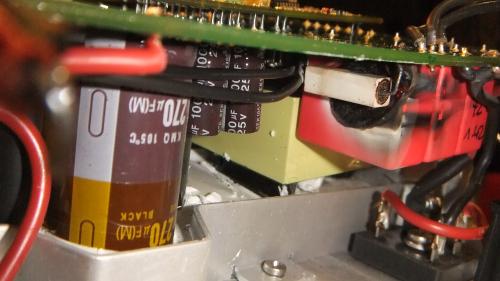
The white resistor is clearly damaged. What is the NTE equivalent for this part (what do I need to know to replace it)?
Do you think the red part is also damaged? Is there any way to verify?
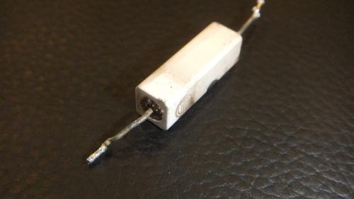
I de-soldered the white part:

Sorry for my dumb electronic questions, and slowness to respond. (insert lame excuse here__________)
If I can get replacement part(s), I will put it back together and give it a try--and report back, of course.
Thanks for your help so far.
Looks like the white part is a high wattage resistor that has been mentioned, I believe, previously as the main culprit for charger failure but it might still be OK, just gotten very hot and melted the red component next to it which has left a load of burnt (red part) plastic all over the resistor making it look dead.
(Ignore the rest of this if I am teaching you to suck eggs! I'm afraid I got a bit carried away. And by 'lead' I mean 'leed' as in the bit of wire coming out the end of the component!)
Try an ammeter across the resistor to see if there is any resistance. It may (normally) be very low - less than 5 ohms - but if it is the one mentioned above I gather it should be 1K (one thousand) ohms but this should be clearly marked - along with the wattage rating e.g. '5W' and sometimes its tolerance - on its side somewhere. See... http://www.welwyn-tt.co.uk/pdf/application_notes/resistor%20marking%20codes.pdf for more on resistor markings.
Obviously, your ammeter should show the correct resistance value - give or take 2-5% or so tolerance. If it is open circuit, it is blown and needs replacing. As you have it out already, you might as well replace it anyway.
The question is, what is the red component that has melted/blown up as that looks well cooked...? Any markings or a close up photo? The other 2 like-looking components next to it are probably all the same so if you can't see the first ones marking, you should be able to see the others.
Replacement parts are usually easily obtainable from electronics shops (is Radio Shack still going?) or by post from the likes of DigiKey (I'm assuming you are in the US). Check that physically the new part is the same size as the old as otherwise it may work in the circuit but it won't fit on the board. Here is a link to digikey for a similar part (I am not recommending it - it is just an example. Satisfy yourself it will work/fit)... http://www.digikey.co.uk/product-detail/en/PSP500JB-1K/PSP500JB-1K-ND/2169781 ... you can see the basic features here. This will probably be ok but it is a non stock item and I think you have to buy a thousand at a time - this is the main drawback of using Digikey - an electronics store will sell one to you but at about 3 times the price! eBay is also useful for parts.
Please avoid excessive use of the soldering iron as too much heat can destroy components (esp silicon-based ones like transistors and diodes) but also can ruin the printed circuit board copper tracks which will come away from the PCB with too much/repeated heat. It's sometimes easier to cut the leads off with side cutters and then de-solder each one, one at a time using a pair of tweezers or long nosed pliers to pull the lead out after heating it with the iron for a couple of seconds. Ideally mount the PCB in something secure (you can buy gizmos to do this) then you have 2 hands for the desoldering.
Use a solder pump (my preference) or de-soldering braid to minimise heat build up and leave a nice clean hole to re-insert the new component. See here for a de-soldering demo... http://www.youtube.com/watch?v=j-_pnc-Qqm8 ... but his guy waits too long to use the pump and has a dirty iron bit - the hot end of the iron - which makes for poor heat transfer and a slower, more potentially damaging solder melt.
Quite often, after removing the bulk of the solder from a lead/pcb, the lead will still be attached with a tiny smidge of solder but otherwise you can 'see daylight' around the lead and so it still won't come out. If you prise one end of the lead towards the space around it with a finger nail or small screwdriver, it will peel away from the hole and come free. This is a bit difficult to describe but if you have a go on a scrap PCB you will soon see what I mean. AT 1:29 on the above video you can see this where the lead he just desoldered is hard up against the LHS of the PCB hole and will still probably be slightly attached still.
Keep us informed and good luck!
Regards, Martin Winlow
Herts, UK
http://www.evalbum.com/2092
www.winlow.co.uk
Regards, Martin Winlow
Isle of Colonsay, Scotland
evalbum.com/2092
The standard charger seems hopelessly complex for such a simple device and low power application.
I don't know if any of you have seen the thread on a DIY charger at ... http://www.diyelectriccar.com/forums/showthread.php/200-build-your-own-intelligent-charger-36627.html ... but this shows how much yo can achieve with very simple, efficient and elegant design for relatively little money. The arduino controller used in this DIY charger can, of course, be programmed to do what ever you want and I expect could quite easily be made interface with the Vectrix's controller and sub systems to correctly control the instrumentation, cutback the controller on a low voltage situation etc etc.
MW
Regards, Martin Winlow
Isle of Colonsay, Scotland
evalbum.com/2092
This charger (ESD) is particular complex, you could make a charger with a rectifier and a few light bulbs. But you have to remember, the Vectrix charger has to pass numerous safety, EMI emissions and susceptibility and HIpot tests and meet power factor requirements. 50% of the circuitry you see in there is to pass these tests and get UL and CE certification.
"particularly" complex...that is
Hi Tony,
I have a bad ESD charger that is already opened, so I can try to measure this resistor as soon as I get home, end of the month.
Cor.
The converter is supplied from the resistor 220ohm5W x2 / connected in series 440ohm /. Resistor is damaged by grounding in the system UCC27324-dual 4 A Peak High Speed Low-Side Power MOSFET Drivers
Thank you for the explanation, and welcome to the forum!
Is there a way to test if the resistor has caused a cascading damage to other components, or is it just a matter of replacing the resistor?
This information may be used entirely at your own risk.
There is always a way if there is no other way!
"Thank you for the explanation..."
I'm glad you understand, Mik - it's gobble-de-gook to me! How/why does the 'grounding' happen?
MW
The resistor is only part of the power inverter. The inverter supplies the high voltage transistors. The power supply consists of several cooperating converters. / A similar solution was used in the LED TV. /. Damaged resistor indicates the current power inverter exceeded. The exchange itself does not make good power supply. Only the replacement of damaged UCC27324 reduce the current. You can say that the resistor is a fuse. Often this solution is applicable to electronic TV.
http://www.datasheetcatalog.org/datasheet/texasinstruments/ucc27323.pdf
Shorting pin 3 and 6 In my circuit pin 3 GND 6 VDD, 5 OUTB. Damaged MOSFET Drivers will not run the inverter high-voltage power transistors
----------------------------------------------------------------------
Rezystor jest tylko częścią zasilacza przetwornicy. Przetwornica zasila tranzystory wysokiego napiecia. Zasilacz składa się z kilku przetwornic współpracujących. /Podobne rozwiązanie zastosowano w TV LED./. Uszkodzony rezystor wskazuje na przekroczony prąd zasilacza przetwornicy. Sama wymiana nie naprawi zasilacza. Tylko wymiana uszkodzonego UCC27324 zmniejszy prąd. Mozna powiedzieć że rezystor jest pewnym bezpiecznikiem. Często takie rozwiązanie stosuję sie w elektronice TV.
http://www.datasheetcatalog.org/datasheet/texasinstruments/ucc27323.pdf
Zwarcie pin 3 i 6. W moim układzie pin 3 GND ,6 VDD ,5 OUTB. Uszkodzony MOSFET Drivers nie uruchomi przetwornicy zasilającej tranzystory wysokiego napięcia
I'm trying to fix my charge managed to remove the PC boards from charger housing and this is a list of what I have observed so far
Two Fans on the charger are not blowing
There is output from filter board of 230V AC to Bridge rectifier (so that means the two fuses are still ok not open circuit)
330V DC output from bridge rectifier to the Main Board
Intermittent output of 175V DC to the NiMH battery from main board
During the present of this 175V from main board I would also hear zip sound from same board
Has anyone come across this problems
Hi All,
Thanks to all of you for posting all this good information here!
Hope that this thread is not too old and that someone is still reading it....
On my Vectrix VX-1 ESD Charger, I heard a loud pop from the charger after plugging in one evening recently.
Subsequent opening up of the charger (with much gnashing of teeth) revealed that one of the power
semiconductors on the edge of the main board failed rather catastrophically:
The part that failed is next to a couple of 32N50C3 MOSFETS made by Infineon. Unfortunately, the
way it blew out obliterated the full part number on the package, so I can't read all the markings on the part. In the
photo, I tried to replace part of the plastic package that fell off. It has part of the package markings:
Does anyone have a photograph or an open charger to be able to look and tell me the number on this part? I just might
get lucky and have the charger work again if I can replace this device.
Thanks,
-Kurt
2007 Vectrix VX-1
Carlsbad, CA USA
Hi Kurt,
I have a non-working charger sitting at my desk at work,
the cover has already been pried off by someone else to look inside
to see if it was something simple, but it appears very complex so they
never bothered to fix it, got another one and gave this one to me.
I can look at it and see if I can make out the part nr.
Note that such a catastrophic failure (completely blowing the part)
may indicate other damage in the circuit - I guess you will find out
once you put it back together. But I suggest that you measure other
parts nearby for short circuit, such as the two mosfets sitting next to it
that could have lead to the failure of this part (Diode?)
BTW, I do not need this charger, so let me know if you are interested in
getting it if you have trouble fixing yours - just pay shipping.
I am in San Francisco south bay area (Silicon Valley).
Cor.
Hi Zoompig - If you can tell me how to get the main board off (I assume this is the biggest one in the top-most photo of your post of Fri, 10/21/2011 - 07:22?) then I'll have a look at my old one - assuming it hasn't failed in the same way! MW
Regards, Martin Winlow
Isle of Colonsay, Scotland
evalbum.com/2092
Thanks, Martin!
Yes, the big board is the 'main board' and is the one in the photos I posted.
Getting the main board off was a real pain. Since the charger I had would be dumpster food anyway if I couldn't fix it, I was a little more likely to risk prying and scraping things.
What I did (which is arguably ill-advised) was to remove the bottom c shaped power filter board and the other small board assembly first. These were a pain because the board standoffs for these boards interfere with the board mounted components as they come out. There is also the connection to the bridge rectifier and 50 Watt resistor to deal with. During charger production assembly, I am pretty sure that they were installed before the main board is mounted and potted in.
I then removed the aluminum dam that held back the elastomeric potting compound. I did this by removing the screws holding the dam down to the casting, and then using a very thin metallic putty knife and a mallet to break the bond between the elastomer potting material and the casing. This involved forcin g the putty knife under the dam and tapping it in (gently!) further with the mallet. I don't recommend doing this in retrospect, but it may be necessary. There are power transformers on the board whose bobbin flanges get close to touching the casting as it is potted in there - be careful to avoid them if you do this.
I then ran the thin putty knife around the outer edge of the elastomer in the gap between the edge of the board and the casting. I avoided doing this where I could see that the torx flat-head screws were holding devices down from the outer cast casing edge. I then loosened these torx screws, and gently pried the main board away from the cast housing and out of the elastomer potting compound. The potting compound did not have a super-strong adhesion to the components on the board, thank goodness.
If I had to do it again, I would try loosening the torx screws first, get the putty knife in where I could on the edge to sepearate some locations of elastomer potting compound from the cast case surface, and then try to pry the main board up without first removing the other two boards. Perhaps another forum reader has tried this and could comment on the success of this technique. There has got to be a better way than the path I took.
I don't know if the thermal design of the ESD charger relies on the thermal conductivity of this elastomeric potting compound, or if it just there for shock and vibration tolerance reasons.
Cheers!
-Kurt
2007 Vectrix VX-1
Carlsbad, CA USA
Hi Kurt.
I finally got my charger open - using the same process as you, there is no other way.
The small PCB does not even come out with the 50W power resistor in place, you *must*
unscrew the resistor to move the small board.
Also, I finally saw that there are 2 holes in the main board to stick a thin screwdriver
through to remove the screws for the "dam".
Anyway - with a lot of wiggling and cutting and prying with a few flat screwdrivers, it
finally popped up.
Then I saw that there was also a crater in my diode, exactly like yours.
Luckily in my case the part that was separated was in 1 piece and still readable:
CREE CSD60020, a Silicon Carbide zero-recovery 600V 20A diode.
http://media.digikey.com/pdf/Data%20Sheets/CREE%20Power/CSD20060D.pdf
Now the two MOSFETs adjacent to this diode read zero Ohms between two of their pins
and my experience with switching power supplies is that usually if the diode blows,
then the transistors are also toast.
In addition to these problems, I noticed a burn mark on the PCB: the next row of
transistors 20N60 has the first one (closest to the diode) also split open and the
PCB trace to the center pin has evaporated from the PCB.
I know that someone has described the repair process of this (ESD) charger before
somewhere here on the site so you might find a better description by searching for it
to know how extensive the damage can be.
Since mine has the same damage as yours, I don't think it is useful to give it to you
but if you like, you can have it for spare parts in case you have damaged anything
on your charger.
Success!
Edit: I did a bit more searching and found the other thread about The Laird's failed charger.
It points back to *this* thread for the pictures that are here, but there is also a link
to a German forum with someone opening the ESD "carger":
http://visforvoltage.org/forum/11739-failed-esd-charger
Hope this helps.
BTW, the Silicon Carbide diode is in the "PFC" circuit, this is the converter that takes
the (rectified) AC voltage and turns it into approx 400V DC so the rest of the electronics
can convert down from that input voltage. It also allows the "Power Factor" to be close to 1
which means no current-spikes on the AC input, but a nice Sine wave.
Hi Cor.
Thanks so much for sharing your experience regarding that main board.
I may take you up on your offer of your dead charger at some point, but
I'll take a good stab at trying to repair the one I have here first.
Your offer is very generous - Thank you.
I'll take a close look at those FETs and for traces that may have cooked a bit
on that main board. I'm not surprised that there is a PFC front end on this
beastie, as they were offering a consumer product into the European market, and
CE is usually fussy about that kind of thing.
I'm tempted to look for a diode that is rated for somewhat higher current but still
has fast reverse recovery and similar voltage ratings. Perhaps that is a fool's errand -
I don't know how much tweaking and tuning they did to optimize this front end circuit when
they settled on a production design.
Again thanks! I'll study the links you provided here and have a go at bringing this charger back
to life.
-Kurt
2007 Vectrix VX-1
Carlsbad, CA USA
My ESD charger failed too. I can see a burnt squarish black thing (looks like a transistor, but on closer inspection the middle leg, which is not connected to anything, does not look like a third leg, so probably not a transistor). It is the square one on the corner of the green wire on the very top circuit board, immediately visible when the charger cover is removed. It is positioned and looks like it is soldered on its bottom flat side to something, which looks like a square patch of metal on the board - does not look like there are any electronic elements under it (and that metal flake is separated from the board - I can lift it gently).
100kOhm b/w the two legs that are soldered, 50kOhm b/w the middle and the one near the green wire, infinity between the middle and the other leg, short between the middle leg and the metal flake on the back of it.
Does anyone have an open charger and can look at the value/type of that thing? And where the middle leg is supposed to connect, if anywhere?
Nothing else that's visible seems burnt or damaged (including the resistors mentioned in the posts above)
That burned black square is an IRFR420 transistor. It may be OK - please measure it as a transistor.
You can see the pic and datasheet here:
http://www.mouser.com/ProductDetail/Vishay-Siliconix/IRFR420/?qs=ehM%252bESVsXgzlRAuHfjawMA==
I see that Mouser no longer carries it - but Digikey apparently still does, else look on Ebay if you do need a replacement.
http://www.digikey.com/product-detail/en/IRFR420/IRFR420-ND/352477
Reason the middle leg is cut, is because it is tied to the metal back, which is also its heatsink.
This SMD mounted package is supposed to be soldered down onto a PCB with heatsinking capabilities or it will overheat easily.
I do suggest that you measure the transistors whose legs can be seen just under the edge of that small PCB in the larger PCB underneath,
all around the edge of the board (they are mounted against the metal enclosure wall around the boards)
My experience has been that the 3rd transistor from the edge (see pics earlier in this thread) is blowing
and I even have a trace burned away to another transistor that has shorted.
I have this (broken) charger sitting open on my desk, if you want it then just pay me the shipping (or arrange pickup).
Since I can't see the other side of the board with the transistors, I can't figure out which ones are their legs, looking from above as my picture shows. I see a row of 3-pin devices. There are 4 sets on the left, 4 sets in the middle, and looks like 3 bigger sets towards the right. As seen from above (i.e., the bottom of the board they are mounted on).
Also, to test these things, shouldn't they be desoldered first?
There is no need to de-solder when you just want to find if there are transistors or diodes that are short circuit.
The row of 3 larger devices on the right is where it is at - the leftmost of the 3 was burst open in the last two chargers that were discussed here in this thread. In my charger, also several of the transistors to the left of that one are shorted.
Success digging in your charger and let me know if you like to get mine. I like to get rid of it in the next month,
else I will need to discard of it since it is not easy to put back together and my office will be moving soon.
OK. Here is a photo of the top edge of the main circuit board, where the transistors' soldering points are visible. The third one from the right is puzzling - there is a U-shaped track on the board that connects its two outside legs together. So it is a short between them, but that's how It has always been - they are on the same track on the board.
The other two big ones next to it, the 4 smaller ones in the center, and the group of 4 transistors on the left all give me some suspect readings. For example, the small ones are not shorted, but around 1 kOhm b/w the two side legs. Touching the middle leg with the + lead on the multimeter (in diode measuring mode) does not change anything. Switching the direction b/w S and D doesn't change much - the resistance is perhaps 100 Ohm less, still around 0.9kOhm (I don't know which keg is which, just assuming the two side ones are S and D, and the middle is the G/switch).
The "burnt" square one that I posted about, on the other hand, has much higher resistance. Touching its gate with the + does not change a thing. So it is not a short (it is 150 kOhm or whatever big number). It does not open through the gate.
I have not used this multimeter for diode testing for a long time, so it might not be working properly, or I may be using it incorrectly. Also, there is some film or sprayed clear insulation layer over the board, making the measurements a bit trickier - I have to scratch it off with the probes to make contact with the legs of the elements...
Can one of you email me the MC firmware mentioned above for the Runke? I bought a Runke that will arrive next week and would be nice to have the bike properly configured.
Also, are there different versions of the Runke charger firmware too? What version should it say everything is in ScooterDiag?
Thanks!
On mine, the big rectangular resistor reads open circuit measured as it is mounted on the board. The one in the picture above (I copied it jere in my post again). Without disassembly I can't see if mine is visibly damaged - I can see a little black spot on the end near me on its side only. I'll have to replace that.
Edit: Any clever ideas how to replace this resistor without disassembling the charger? I think, because it is already open circuit, I can just solder a new one on the top of it on the visible side of the board. There is enough clearance there under the cover (and I can reposition it with some wire if needed). The old one will just hang where it is now or worst case, drop lose and rattle inside... Thoughts?
Martin/anyone: the 5W / 1kOhm - was this an example for the value of the rectangular resistor or you think this is the actual value of the resistor? I need to find a replacement for mine...
Pages