Hi I was wondering if anyone knew how the controller, throttle and halls sensors operated?
My understanding is that the battery sends 36 volts to the controller (which part inside the controller, I dont know) then each of the 6 power transistors send a half wave to the motor, which creates a 3 phase power supply to a delta or wye motor? How does the throttle work in this, does it just send a resistance value to the controller and how does this value control the freq. of the transistors? Do I have this wrong? It is helpful to know what is going on when I troubleshoot.
Thanks and Regards


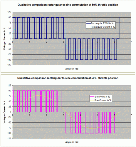
Yes, the throttle value adds another dimension to the transistor's half wave as you called it. The throttle is either a potentiometer (proportional resistor), but better a contatct-less hall sensor + magnet setup, that is normally supplied 5V DC from the controller and outputs a proportional voltage between 0 and 5V (should normally be cut at both ends to 0.5 ... 4.5V for a little leeway due to drift) to the controller depending on position. The transistors are then switched on and off DURING their respective half wave roughly at the rate dictated by throttle position, i.e. at 2.5V = 50% throttle signal the transistor would be switched on and off 50% of the time respectively. ON-time during the half wave is changed according to throttle position, thus controlling the electrical current and thus torque/power generated in the motor. It is called PWM, Pulse Width Modulation. To smoothen out the commutation cycle the PWM can additionally be modulated according to the exact rotor position to create a sine waveform. If I figure out how to upload a pic to here I will insert a simplified graph to better illustrate what I just wrote.

My rides:
2017 Zero S ZF6.5 11kW, erider Thunder 5kW
thanks for your reply and graphic. So what role does the IC chip play? it times the sequence of the pulses? How is power supplied to the chip? The 36 volts that enter the controller, what are they connected to?
raid
power comes into the controller ----> (connected to what)---------->some of that power is directed towards the pot or halls sensor throtte?)---------> that signal is applied to the gate of the FETs or power transistors?)--->
the transistors send a pulse to the winding of the motor, timed by the IC chip?
is this the correct order of events?
thanks and regards,
raid
Also, when troubleshooting, can I put a voltmeter on the output of the controller to the motor to test for correct voltage, or must I use a ocscilliscope? Must the halls sensor be connected to the motor befor I get any reading? What is the best method of testing the controller if the motor isnt turning when throttle applied?
Thanks for all the help
raid
Those are heaps of questions that mostly go way beyond my more mechanical scope! But apparently you have a pretty good grasp on what goes on. Without hall sensors correctly connected to a controller no PM synchroneous motor will turn - only if the controller should be a sensorless one that attempts to guesstimate rotor position via the back-EMF generated by the motor.
I see no sense in knowing EVERY aspect and detail of the inner workings of an electric vehicle simply to be ready for ANY conceivable fault IN CASE it should fail, unless you plan on building the whole lot yourself, from the ground up. You appear to know enough to be able to choose, order and operate an electric ride, and if you should run into trouble with post it here to get answers for REAL, not just immagined faults :-)
My rides:
2017 Zero S ZF6.5 11kW, erider Thunder 5kW