Dear all,
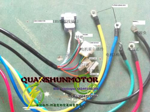
I have a new controller and i need help with the wiring. It is for a big electric scooter. I dont know how to connect the power lock and the brake wire. I guess the power lock wire has to be connected with the ignition. The ignition has 4 wires now..
The brake wire will have to be connected with the brake wires of course.. But how? The red with this wire and black with black of the battery?
Please help!


Recalling the instructions on a 60 volt controller just bought on ebay , that mentions a DOG .... DOOR lock. That is your POWER LOCK connected to ++ pos BIG RED (your harness key switch ++ red pos)BRAKE wire acts as NEGATIVE - - but brake lever must be tense and connected before you " Let the dog lose or OPEN THE DOG LOCK " Your harness may have a diode or not. Good Luck
Do not connect the red brake wire to positive The positive goes on the other side of the bulb . ALL three (3) BRAKE WIRES (ONE TO EACH BRAKE LEVER and another to then rear lamp , they go connected to that single little
red brake wire
Thnx for your anwser! Just to be clear; I have 2 brakes with brake wires. These brake wires have each 2 wires, black and red. So connect these to the brake wire of the controller? All 4 or just the reds? And the black wires then?
and the harness key switch with 2 wires?
thnx for your help
Sorry don't know much about your controller or harness but my suggestion is to use a multimeter an get a diode of about 8 volts in between for testing signal and it probably would be enough to act the lamps .....It seems you do not have the one single wire HIGH BRAKE configuration but the LOW BRAKE two wires . For the two wire key switch config. ; one end goes Big RED ++ the other end goes to your controller DOOR LOCK
It looks kind of orange in color on yours . Multimeter and diode and you'll be fine.