My parents actually met Ronald Reagan at a party at the Lesher Mansion (we used to spend summer vacation time with Dean's son Stan) when Reagan was governor. I used to watch William F. Buckley on a regular basis. I've voted Republican since forever. William F. Buckley was incredible to watch and listen to because his mind was so sharp and he was so flexible in his thoughts. It was the way conservatives were "supposed to be".
So your mental image of who I am is obviously not very good.
But I'm not Libertarian and actually don't like that direction because all the Libertarians seem to have terrible manners and just blurt out things. Reagan was a kind soul that would only get angry if the situation really required it.
Anyway...
My thinking is that the Mid Drive is an "easier" way to cover a wide range of speeds. The wider the speed range you must cover the more likely the motor falls outside it's preferred powerband.
On a racecar you need to go from 0-150 mph and if that were a single speed your torque requirement below 60 mph would be extreme ASSUMING there was no limit on power.
Since the racing is "Input Limited" you aren't going to blow up the transmission because it's power is known and limited. Multispeed transmissions can be used without worry.
Cause and Effect:
Unlimited Power -> Single Speed
Limited Power -> Multispeed
---------------------
The alternative path would be to create an extremely thin high efficiency motor which has efficiency that is so high across such a wide powerband that you can not need gears. That really will stretch the limits of motor design as you increase the size of the motor making it more fragile. The project going on at ES is an example of "pushing the envelope" of direct drive. (it too can fail due to reliability problems, being too fragile)
Multispeeds used in eRacing are an "easy choice" because you can use well known parts and have high levels of confidence of success. Without the 200kw "Input Limit" that eRacing series would be unworkable because people would "push the envelope" on power and batteries and it would be like the days in Formula One when the "Turbo Wars" gave a huge advantage to those that got it right. They wanted to avoid that.
Ebikes have "Output Limiting" of either 250, 500 or 750 watts depending on where you live. In order to live in hilly places those multispeed gears make life easier.
It also just seems natural to use a derailler with the motor because it's already there.
The argument of single speed vs multispeed on bicycles is discussed here:
Having a more triangular shape reduces the flux path. The room for the coils gets reduced, but ideally you can use less copper anyway because of the magnetic flux switching behavior.
Still need to tie it all together with the ratcheting mechanism.
Should be very torquey and with the ratcheting mechanism heavily geared down.
...at some point I'll switch from "paint" to AutoCad. I'm a little slower with AutoCad, so the paint program makes these sketches easier.
.
.
The "Freemason Motor" only works if you can think symbolically. (joke)
.
The Romans did use ratchets and gears in charging their ballista, that way one soldier could ratchet it up and then fire it. And the Romans didn't even invent it themselves, that was a spoil of war from conquering the Greeks.
With a hammer, a chisle can be made. With a hammer and chistle, files can be made. With hammer, chisle, and file anything else can be made.
Kaishan k500w retired, Merida TEV500 on indefinite sabbatical, currently using a Currie E-zip Trailz.
Though the Romans used the "water wheel" extensively, I'm not sure if the "Ratcheting" idea was around back then. Unless it existed earlier I think Leonardo Da Vinci was the true inventor.
The Romans did use ratchets and gears in charging their ballista, that way one soldier could ratchet it up and then fire it. And the Romans didn't even invent it themselves, that was a spoil of war from conquering the Greeks.
With a hammer, a chisle can be made. With a hammer and chistle, files can be made. With hammer, chisle, and file anything else can be made.
Kaishan k500w retired, Merida TEV500 on indefinite sabbatical, currently using a Currie E-zip Trailz.
Yes, the idea of a "Ratcheting Mechanism" is very, very old.
It's one of the earliest ways to increase torque.
If one can use a "Ratcheting Mechanism" on an ebike it seems to me you could achieve very high torque at very low rpm (100 rpm) and have a more reliable Mid Drive.
Still fiddling around with "how" it might look.
It has to be extremely efficient in order to be better than regular gear reduction. And less weight would be great too.
First, the magnetic flux for a given coil will create some force.
Second, the distance from the pivot point will determine the leverage that this force will apply.
Third, the pivot will act upon "something" such as a geardown unit, the effective gear ratio will again increase leverage for the system. (through the "Ratcheting Mechanism")
---------------
The image above implies an effective two stage gear reduction.
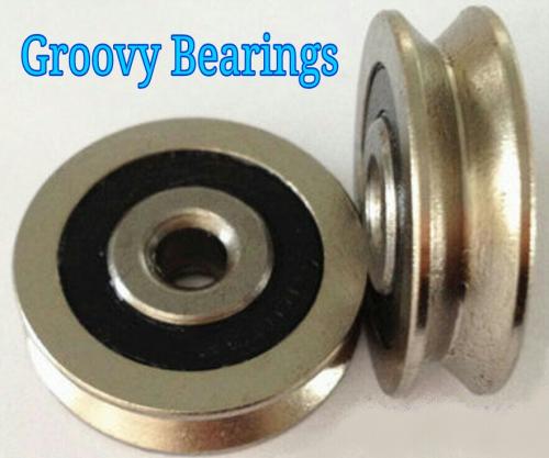
For the "Ratcheting Mechanism" it would be nice that during the recoil phase of the cycle that the pawl doesn't drag across raw steel. These "v groove" sealed bearings would allow a solid contact area, but it would spin slightly on recoil.
Ideally it would be great to find some very hard plastic for the contact area because then it would be less noisy. "Click, click, click" is better as "clunk, clunk, clunk".
Like the geared hub motors, using plastic gears reduces noise.
One of the more annoying issues with motors is how the heck you get the motor to switch things on and off. With a brushed motor you have friction in the switch because it has to drag across raw metal. With a brushless motor you need hall sensors coordinated with complex electronics to get everything working as it should.
The "Ratcheting Mechanism" has a physical configuration such that it naturally is capable of turning a switch on and off.
So "ideally" this system could run with a regular PWM controller.
If you really wanted to go "old school" you could run a low voltage battery (1S is 3.2V) and then match the coil windings so that the "time constant" is optimal for running at 100 rpm. Assuming you are designing for low power (say 100 watts) the system could be run with a button.
Most people want the most power possible, so then you need a throttle and controller and more voltage.
The single cell (3.2V) battery has an advantage because it cannot become imbalanced. This means no BMS and charging is less complex. Reliability goes up with a simple battery.
For 100 watt power this could be really impressive for it's simplicity.
...it's the kind of high reliability, low weight, low complexity solution that is missing now.
.
At the end of every tv season there is a "cliffhanger" episode.
You get left hanging.
Well I'm going to do this with the "Ratchet Gear Porn".
The next step is to get serious about things like FEMM simulations and dig deeply into how effective a ratchet based slow turning (100 rpm max) Mid Drive might be.
This will have to wait until "next season" which will be next winter.
I guess this qualifies as "exciting scenes" of future episodes. ;)
If you pedal at roughly 2 revolutions per second (120 rpm) and there are 10 cogs in your ratcheting gear, then your electronic configuration requires a "time constant" of 50 ms or 20 Hertz.
...is really fantastic because you can view and adjust in realtime.
High resistance would involve many turns of copper in the coils. Might be hard to achieve the low inductance number. Will have to use FEMM to get an idea if low voltage (3.3 v) is possible.
----------------
Separate topic:
In order to reduce noise the ratcheting roller can be a solid steel "v groove" sealed bearing, but the ratchet gear itself could be plastic. The gear will wear faster than the roller. (a good thing). When it does wear out you replace it like you would any ordinary chainring.
.
.
I'll add that doing the circuit simulation in realtime is a lot of fun and it really shows interactively how much easier everything is with more voltage. With high voltage you can push through a lot of heavy inductance and get quick response. Low voltage is very sluggish and inductance and resistance extends the duration of the time constant. It's actually difficult to get 3.3 volts to function effectively even at 20 Hz (50 ms per cycle) when you assume a large coil.
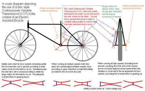
If the overall problem is that electric motors run most efficiently at high rotational rate. And, in the context of a light electric vehicle that is problematic due to both the desire for variable speed control and "uphill" climbing conditions. Then, wouldn't the solution be to use variable gears? Yes. Already covered I know, with among other issues being cited is the need to manually change gears. So, why not borrow a solution from ICE scooters, on one side of the rear wheel have your human power drive train (variable gears optional), and on the opposite side have a scooter style Continuously Variable Transmission (discs that spread or close by centrifugal force according to rotational rate on each pair of discs thereby providing a variable circumference for a belt to rotate on). The two overwhelming problems that would likely be cited with this solution is that, in a ICE situation, a clutch is needed for shifting to/from forward, neutral, and reverse, and that there is a certain inefficiency concerning the friction in this scenario. The first concern is negated by using an electric motor which can shift to/from forward, neutral, and reverse electrically, and in most cases light electric vehicles only move in one direction (forward) under power, again not a concern. As two the second concern, friction losses become large only when it is expected to carry/transfer large amounts of power, you cannot honestly consider 250-750 watts a lot of power, and as losses would also be a percent, they would not be likely to amount to much loss overall. This would probably overall increase efficiency and hill climbing capacity, all done automatically with infinite variability. Of course, my statements have no calculations, research, or personal experience by me to back them up so that does need to be done by someone, possibly me eventually, probably someone else sooner. Thankyou.
With a hammer, a chisle can be made. With a hammer and chistle, files can be made. With hammer, chisle, and file anything else can be made.
Kaishan k500w retired, Merida TEV500 on indefinite sabbatical, currently using a Currie E-zip Trailz.
If the overall problem is that electric motors run most efficiently at high rotational rate. And, in the context of a light electric vehicle that is problematic due to both the desire for variable speed control and "uphill" climbing conditions. Then, wouldn't the solution be to use variable gears? Yes. Already covered I know, with among other issues being cited is the need to manually change gears. So, why not borrow a solution from ICE scooters, on one side of the rear wheel have your human power drive train (variable gears optional), and on the opposite side have a scooter style Continuously Variable Transmission (discs that spread or close by centrifugal force according to rotational rate on each pair of discs thereby providing a variable circumference for a belt to rotate on). The two overwhelming problems that would likely be cited with this solution is that, in a ICE situation, a clutch is needed for shifting to/from forward, neutral, and reverse, and that there is a certain inefficiency concerning the friction in this scenario. The first concern is negated by using an electric motor which can shift to/from forward, neutral, and reverse electrically, and in most cases light electric vehicles only move in one direction (forward) under power, again not a concern. As two the second concern, friction losses become large only when it is expected to carry/transfer large amounts of power, you cannot honestly consider 250-750 watts a lot of power, and as losses would also be a percent, they would not be likely to amount to much loss overall. This would probably overall increase efficiency and hill climbing capacity, all done automatically with infinite variability. Of course, my statements have no calculations, research, or personal experience by me to back them up so that does need to be done by someone, possibly me eventually, probably someone else sooner. Thankyou.
I was thinking of something more along the lines of this:
With a hammer, a chisle can be made. With a hammer and chistle, files can be made. With hammer, chisle, and file anything else can be made.
Kaishan k500w retired, Merida TEV500 on indefinite sabbatical, currently using a Currie E-zip Trailz.
That's a CVT that's been around a while. The problem with most CVT systems is that they tend to be heavy and waste energy in the form of heat because there is always some sort of slipping going on.
.
.
The D-Drive uses dual orbital gears and so there is no slipping. In order to vary the speed of the output a secondary input causes the orbitals to rotate forwards or backwards.
...I find that very interesting because you REALLY get a CVT without slipping.
The D-Drive could deliver maximum efficiency in the primary drive and then use a smaller input power that is less rpm sensitive. Step motors seem ideal for the secondary.
So it's not possible to run the control shafts using a small electric motor as we said in the video - in fact, the engineering report is quite clear on the fact that the 'control' motor needs to be just as powerful as the 'input' motor: "Our designation of 'Input' and 'Control' shafts in this report is arbitrary in that both would conventionally be used to provide power. There is no inherent character of the mechanism that requires the input to be the dominant power-providing element. The torque provided by the control shaft will typically be of the same magnitude as the torque provided by the Input shaft... the Input and Control should be considered as parallel power paths rather than as 'power ' and 'control' elements respectively."
...I was afraid of that.
It doesn't necessarily rule this idea out, but only one motor operates at optimal rpm all the time while the other has to work well across a wide range of rpm. What's worse is they both require the same overall power.
The good "old fashioned" (to me) multi-speed mid drive is hard to beat !!!
Maybe a super high tech ultra thin disc shaped hub motor could show an improvement, but that remains to be seen. That's all going to come down to successful fabrication and materials. (hard to do)
.
The searching (and waiting) continues...
The "Ratchet Gear Porn" is looking as the best alternative at this point, With a ratchet you concentrate your force into a small space and gain a lot of leverage through gear reduction. It's really the only alternative I've come up with.
If you rotate magnetic cylinders configured as a Halbach Array they create either a rotating field or if the magnets rotate a stationary wave.
Previously I had calculated for a mid drive configuration which would create a narrow width, but this seems better for a rear hub.
.
.
The weight of the copper coils is concentrated in the center and there are air gaps around the magnets so cooling is good. Rotational inertia is low because the spinning magnetic cylinders are lighter than a silicon steel shell might be. There is no "switching" of the electric field because the flux rotates around the field mechanically, so there is no electrical rpm to consider.
.
Replace the larger front chainring with a 300 tooth gear made of a non-metallic material (plastic) which will reduce noise. Add a 3000 rpm electric motor with a hardened steel 10 tooth gear.
Freewheels are optional, but probably a good idea. (eventually)
By using a combination of plastic and steel for the gears you encourage the larger gear to wear out more quickly than the smaller. Maybe every 10,000 miles you might need to replace the plastic gear which is an easy maintenence item.
Chains have been tried, but at these speeds a chain generates too much vibration and noise, so this gives a simple solution that avoids the usual pitfalls. It would be impossible to have a 10 tooth to 300 tooth chain combination, but with gears it's possible. Final gear reduction ratio (1:30) will bring a 3000 rpm motor down to 100 rpm which is right where you need it to be. The plastic gear can be fairly wide (1/4") and that increases tooth strength. Excess material can be removed in ways similiar to ordinary chainrings.
The most critical aspect (technically) will be the creation of the 300 tooth plastic gear because it has to be strong and perfectly shaped. Mounting needs to be done in such a way that it's impossible for any excess gaps to exist between gears. In the beginning it might be wise to avoid freewheels because they would introduce such gaps.
.
.
A Double Helical Gear design would increase strength and also allow for a freewheel because side-to-side sloppiness would be less of a problem. Assuming you make the large gear of plastic it's nothing but an alteration in the molding. Cutting the smaller gear in steel is more difficult however. This will further reduce noise.
Calculation:
Assume we want a 40dp spur gear. Also we want 300 teeth:
Pitch Diameter = Number of Teeth / Diametrical Pitch (dp)
Pitch Diameter = 300 / 40
Pitch Diameter = 7.5" ...which is the size of a front chainring.
...such fine teeth might be unworkable, so you would have to find the limits of practicality.
.
In this scenario we use a 240 tooth 32dp gear. The small gear is reduced from 10 teeth down to 8 teeth which might be questionable. Final ratios are the same and size is the same, but the teeth are bigger and so more likely to handle the load.
.
...I'm pretty sure those are 32dp teeth.
For a first attempt ordinary steel spur gears seem to make the most sense and they can be custom made at what (we hope) is a reasonable price.
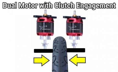
The idea would be to use two motors and have rubber wheels on them that grab the rim where the brake pads normally grab. You then set up a clutch cable and mechanism so that you must either engage or disengage the clutch to get contact. (probably engage is better)
I'm not sure if this is the most efficient idea... but it would be a heck of a lot of fun because you can crank the throttle wide open and then slip the clutch, which is a way to get a temporary reduced gear ratio.
Just on the basis of fun it might be worth doing.
If the clutch is disengaged then it freewheels... if engaged regen.
Hmmmmmm... maybe a true clutch type action is best.
Ah ha! Got it... use a low motor current setting with the motors so you can't crank the throttle and get too much heat if you were at a stop. That way if you need power you have to slip the clutch to build some rpm which will get you power. This will result in heat on the rubber wheels and NOT the motors, which is good. :)
Essentially any clutch like design is interesting, but manual rather than automatic. In past posts I've done a lot of eddy current hysteresis clutch ideas, but there are times to slip the clutch and other times you shouldn't.
Unfortunately some states actually explicitly ban manual clutches, so that's a problem.
.
.
...there have been abundant attempts at "friction drive" but they tended to rub on a tire that is exposed to dirt and water. By moving the contact back to the rim (from both sides) you avoid the dirt and water problem. Also, with the clutch action you add some fun. You also aren't going to wear out your tire due to motor contact.
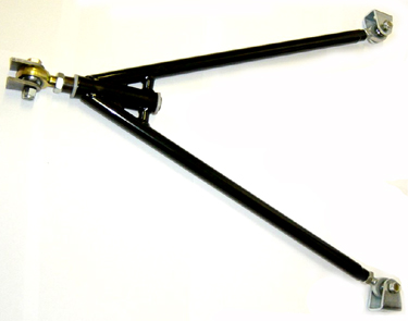
Mounting the motors below the rim actually makes more sense because you avoid tire clearance issues. I think a wishbone type linkage for each motor would be ideal. (two pivot points in a wishbone will be stronger for the same weight)
.
.
...I'm thinking maybe orienting the pivots so they are on the upper chainstays and have the motors back behind the pivots.
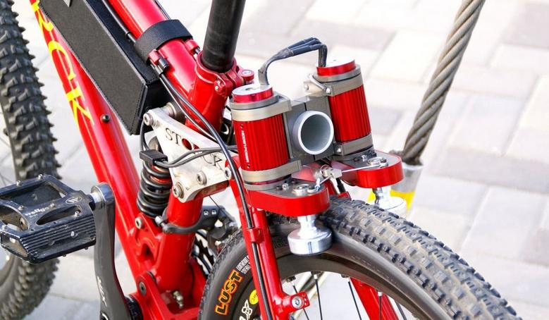
Our main features:
- Motors or automatically releasable on demand
- Low weight of the complete electric bike (from 16.90 Kg)
- Autonomy in hilly courses (70 to 150 km)
- Sports range (electric bike S3, V3 and carbon models)
- Comfort range (electric bike models C2 and D2)
- Designed and manufactured in France, they are sold live for a very competitive cost.
-------------
A very professional product in my opinion. It resolves the whole geardown problem by using the surface of the bicycle rim. The efficiency is going to be good because the motors spin at high rpm and the contact is smooth, but probably with good grip.
Nice.
.
.
This goes a step back and rubs against the tires sidewall. I suppose the tire and sidewall both wear out normally anyway, so as long as the wear rates are similiar it should be okay. Flex in the sidewall will reduce efficiency compared to the custom rim of the Cybien.
The Cybien reports impressive range and durability. Reports of 10,000 km without mechanical failure are believable because there are no gears to wear out. Range of 100 km per charge.
SUMMARY OF THE PRESENT INVENTIONIn the present invention a pair of substantially identical electric drive motors, each having a drive roller mounted on the end of its shaft, are mounted one on each side of the rear wheel of the bicycle. The tire is pinched between the two drive rollers by a tension bar which can be adjusted to provide a spacing between the rollers that is slightly smaller than the thickness of the tire. This pinches the tire slightly between the two drive rollers and employs the pneumatic resilience of the tire itself to provide the desired frictional drive between the two rollers and the tire. Since the only force between the rollers and the tire is provided by the link between the rollers themselves, the two forces against each side of the tire are exactly equal, and therefore the frictional drive of both rollers must be the same.
I'd prefer a clutch and I think using the tire sidewall is less efficient, but the patent for the basic idea goes back to at least 1975.
The next obvious progression is to mold actual teeth into the rim so that you have a:
"Geared Rim"
One might use a single motor with a slight gear reduction.
Side-to-side gears are setup so that normal rim deviations are accounted for with a free floating mount. Since the rim width can be assumed to remain constant you can have a preset gap which guarantees proper gear contact.
This will not permit clutch like behavior, but it should be possible to stop the bike and disconnect the motor if you don't want to use it. It might be okay to disconnect and connect while riding, but probably not under power.
Efficiency should be very good and the potential to use a single motor has it's advantages.
--------------
Another variation might be to put the gear teeth on the inside of the rim on just one side. You now have an even less complicated design requiring a single motor and very high efficiency.
As long as the rim remains true in the round direction the side-to-side deviations are not a big issue.
This will require a specially built rim, but a DIY design could be done by bending a linear track and then bolting it to the inside of the rim.
• CNC Machined Billet T6 Aluminum Motor Can
• High Purity Copper Windings
• 4mm Bullet Connectors Pre-installed
• Powerful Sintered Neodymium Magnet
• Precision Engineered for Maximum Energy Conversion
• Water Cooling Jacket Pre-installed
Specs:
RPM/v: 620kv
Winding: 2.5Y
Max voltage: 37V (10S)
Max Current: 105A
Max Watts: 3050W
Resistance: 0.03ohm
No Load Current: 0.7A
Can Diameter: 39mm (actual motor diameter)
Can Diameter inc. Water Jacket: 49mm
Can Length: 84mm
Shaft Size: 5mm
Weight: 508g
Motor Connector: 4mm bullet plug
.
.
High Pole Count vs Low Pole Count
For many years I've dreamed of a mid drive that combined a very high speed low pole count motor and a complete transmission system with multispeed gearing. To my knowledge it's STILL not in existence yet.
The debate really comes down to high pole count vs low pole count motor design.
There is a finite "Electrical RPM" no matter what you do so:
"Pole Pairs" * "RPM" = "Electrical RPM"
From a design perspective you trade space for speed... higher speed can be smaller (diameter) and that can translate to being lighter.
Racing gasoline motors have attained speeds of 15,000 rpm and yet our ebikes tend to run at around 4,000 rpm because our low tech fabrication skills have prevented us from taking it any further.
But the advantages of an Inrunner motor with a lower pole count and water cooling is rather obvious. The compactness of the design allows the magnetic flux within the motor to be more concentrated and since the faster you switch "per magnet" the more power you will produce "per weight". Electrical RPM tends to limit our ability to max out our magnets when pole counts grow too large, so the bigger things get the more weight we waste with excess iron.
So I can imagine this "Utopia" for ebikes with a compact high speed, low pole count, multispeed, water cooled, inrunner, dual freewheel mid drive.
But just don't ask me to build one. ;)
Any hungry newcomers with high tech resources up to the challenge?
Hi, I found this thread by "accident" yesterday.
You deserve congratulations for doing such an excellent job with explaining all those ideas.
Regarding your Clicker idea, with the solenoid driving a ratchet, I think that the idea could be much more easily implemented by using a One-way clutch instead of the ratchet & pawl. Those clutches are also called Sprag clutches, and they come in all sizes and forms.
See here: One-way clutches
Those clutches are completely silent, and they do not require a definite stroke for advancing. The slightest movement is enough to make them engage and transmit drive. And in the reverse direction, they slip easily without much drag.
One of those could be installed on the shaft that holds the left pedal (I forget the name ...). Then, by attaching a lever to the outside race, you link your solenoid to it via a small arm.
To augment efficiency, the best thing would be a bi-directional solenoid like you're proposing, to solve the problem of residual magnetism, but also to be able to get drive on both strokes of the solenoid.
The way to do this is to put 2 One-way clutches side-by-side on the shaft. I won't try to make a drawing it because it would take me hours to do the same thing that you do in minutes LOL, but it is set-up like this.
When viewed from the side, the first clutch is linked to the solenoid as I explained above. Let's say that its actuating lever is vertically going up, and the small link attached to it goes laterally to the solenoid.
The second clutch will then have its actuating lever going vertically DOWN, and from there the small link goes to the solenoid.
On each stroke of the solenoid, regardless of if it is a Pull or a Push, the 2 clutches will rotate in an opposite direction from each other (because one has its lever going UP while the other has its lever going DOWN), and one of the 2 clutches will be driving while the other will be freewheeling.
I'm hoping that my explanations are clear enough, and I'm sure that you will then make a nice drawing of this ;o)
The funny thing is I actually used a sprag clutch on my ebike, but after some time (and because of power levels well above it's design limit) the sprag clutch wore out and I replaced it with a fixed drive.
What is truly beautiful about the idea is that a sprag clutch can be extremely quiet.
Simplified version might look like:
.
.
The crudeness of the big ratchets and all the noise associated with them does discourage doing the idea, but switching to the appropriately sized (for power) sprag clutch could allow the ratcheting behavior that is needed.
Very nice... will have to think about it more, but I think you've made a big leap forward with the idea.
Having two solenoids makes sense, but having one and a spring is easier.
Compared to all the exhaustive technical skills to produce high rpm and heavily geared down mid drives the simplicity of a sprag clutch and solenoid seems like a refreshing relief.
Someone needs to do this eventually. Hmmmmmmm... at present I don't have any workshop to work in, but that could change.
.
Hi safe,
the problem I see with a solenoid-driven crank is that it is basically a fixed-torque drive.
If we look at a normal electric motor, when variable power is applied to it, it will actually produce more or less torque.
Then, the resulting rotation speed will be inversely proportional to the friction/drag that the motor must overcome. So RPM will vary smoothly and the driver has time to adjust throttle position to obtain the acceleration/speed he desires.
With a solenoid-driven bike, if you vary the throttle, you can vary only the frequency of the strokes, because it would be difficult to vary the "strength" of the solenoid. Too little and it doesn't move, and more than enough doesn't make it move any farther... The solenoid is always at full power, basically.
So you are left with a drive that is very sensitive of the throttle position. The pulse rate, and hence the bike speed is directly affected by throttle position. Of course, it is possible to add some filtering and delay to the control signal but I don't think that would be enough.
I think that a good electric drive must give the feel of a gas-powered car. If you set the throttle at a particular position, the car will accelerate less & less strongly while the speed will increase more & more. On deceleration, it's the same. On a street bike we cannot have that deceleration effect because of the freewheel in the drive. The motor cannot decelerate the bike.
It could, by removing the freewheel, but then would it become a "motorcycle"? ;o)
I'll have to think about this...
Pedal speeds are narrow... usually from 70 rpm to 100 rpm.
Very rarely does one pedal at, say, 20 rpm, because your legs prefer about 85 rpm.
So the idea would be to optimize everything for about 85 rpm.
Final gear ratios are determined by the derailler.
------------------
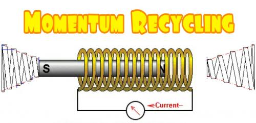
I was also thinking you could set up the solenoid with a spring at both ends. That way you can sort of "bounce" back and forth. Would have to play with some ideas. But using a magnet as the cylinder you should be able to make power in both directions and the two springs would "contain" that energy. There would be an empty "unsprung" center area which is driven by magnetic forces and the outer extremes are assisted by the springs. The springs effectively "recycle" the rebound energy that would normally go to waste.
.
.
What I really need to do is some FEMM simulations.
.
.
The magnetic force "powerband" of a solenoid like device is alterable, so with some work you could create the powerband you want.
The advantage of concentrating all you power into one spot is compactness and usually efficiency. But these things take some time to figure out.
The Sprag Clutch idea is great and products can be purchased for about $20. 140 Nm is a very large torque for a Mid Drive, so it would be very durable.
.
The solenoid would be in fact a rotary actuator.
As happens often with solenoid setups, you have to fight a spring.
However, with a bi-directional solenoid, or bi-directional actuator, you don't have that inconvenient.
I've made a primitive drawing of the bi-directional system with 2 sprag clutches.
When the red clutch drives, the blue one is resetting, and inversely.
Well, apparently, my upload doesn't seem to work...

.
http://en.m.wikipedia.org/wiki/Dean_Lesher
My parents actually met Ronald Reagan at a party at the Lesher Mansion (we used to spend summer vacation time with Dean's son Stan) when Reagan was governor. I used to watch William F. Buckley on a regular basis. I've voted Republican since forever. William F. Buckley was incredible to watch and listen to because his mind was so sharp and he was so flexible in his thoughts. It was the way conservatives were "supposed to be".
So your mental image of who I am is obviously not very good.
But I'm not Libertarian and actually don't like that direction because all the Libertarians seem to have terrible manners and just blurt out things. Reagan was a kind soul that would only get angry if the situation really required it.
Anyway...
My thinking is that the Mid Drive is an "easier" way to cover a wide range of speeds. The wider the speed range you must cover the more likely the motor falls outside it's preferred powerband.
On a racecar you need to go from 0-150 mph and if that were a single speed your torque requirement below 60 mph would be extreme ASSUMING there was no limit on power.
Since the racing is "Input Limited" you aren't going to blow up the transmission because it's power is known and limited. Multispeed transmissions can be used without worry.
Cause and Effect:
---------------------
The alternative path would be to create an extremely thin high efficiency motor which has efficiency that is so high across such a wide powerband that you can not need gears. That really will stretch the limits of motor design as you increase the size of the motor making it more fragile. The project going on at ES is an example of "pushing the envelope" of direct drive. (it too can fail due to reliability problems, being too fragile)
Multispeeds used in eRacing are an "easy choice" because you can use well known parts and have high levels of confidence of success. Without the 200kw "Input Limit" that eRacing series would be unworkable because people would "push the envelope" on power and batteries and it would be like the days in Formula One when the "Turbo Wars" gave a huge advantage to those that got it right. They wanted to avoid that.
Ebikes have "Output Limiting" of either 250, 500 or 750 watts depending on where you live. In order to live in hilly places those multispeed gears make life easier.
It also just seems natural to use a derailler with the motor because it's already there.
The argument of single speed vs multispeed on bicycles is discussed here:
http://en.m.wikipedia.org/wiki/Single-speed_bicycle
.
.
Still fiddling with this design.
Having a more triangular shape reduces the flux path. The room for the coils gets reduced, but ideally you can use less copper anyway because of the magnetic flux switching behavior.
Still need to tie it all together with the ratcheting mechanism.
Should be very torquey and with the ratcheting mechanism heavily geared down.
...at some point I'll switch from "paint" to AutoCad. I'm a little slower with AutoCad, so the paint program makes these sketches easier.
.
.
The "Freemason Motor" only works if you can think symbolically. (joke)
.
The Romans did use ratchets and gears in charging their ballista, that way one soldier could ratchet it up and then fire it. And the Romans didn't even invent it themselves, that was a spoil of war from conquering the Greeks.
With a hammer, a chisle can be made. With a hammer and chistle, files can be made. With hammer, chisle, and file anything else can be made.
Kaishan k500w retired, Merida TEV500 on indefinite sabbatical, currently using a Currie E-zip Trailz.
.
Good point.
Yes, the idea of a "Ratcheting Mechanism" is very, very old.
It's one of the earliest ways to increase torque.
If one can use a "Ratcheting Mechanism" on an ebike it seems to me you could achieve very high torque at very low rpm (100 rpm) and have a more reliable Mid Drive.
Still fiddling around with "how" it might look.
It has to be extremely efficient in order to be better than regular gear reduction. And less weight would be great too.
.
.
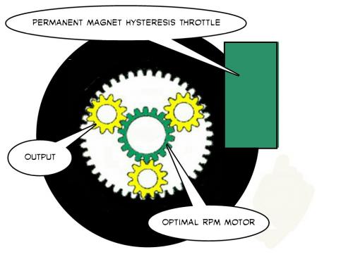
What are the component parts of torque?
First, the magnetic flux for a given coil will create some force.
Second, the distance from the pivot point will determine the leverage that this force will apply.
Third, the pivot will act upon "something" such as a geardown unit, the effective gear ratio will again increase leverage for the system. (through the "Ratcheting Mechanism")
---------------
The image above implies an effective two stage gear reduction.
(very simple too)
.
.
A very small issue.
For the "Ratcheting Mechanism" it would be nice that during the recoil phase of the cycle that the pawl doesn't drag across raw steel. These "v groove" sealed bearings would allow a solid contact area, but it would spin slightly on recoil.
Ideally it would be great to find some very hard plastic for the contact area because then it would be less noisy. "Click, click, click" is better as "clunk, clunk, clunk".
Like the geared hub motors, using plastic gears reduces noise.
.
.
One of the more annoying issues with motors is how the heck you get the motor to switch things on and off. With a brushed motor you have friction in the switch because it has to drag across raw metal. With a brushless motor you need hall sensors coordinated with complex electronics to get everything working as it should.
The "Ratcheting Mechanism" has a physical configuration such that it naturally is capable of turning a switch on and off.
So "ideally" this system could run with a regular PWM controller.
If you really wanted to go "old school" you could run a low voltage battery (1S is 3.2V) and then match the coil windings so that the "time constant" is optimal for running at 100 rpm. Assuming you are designing for low power (say 100 watts) the system could be run with a button.
Most people want the most power possible, so then you need a throttle and controller and more voltage.
The single cell (3.2V) battery has an advantage because it cannot become imbalanced. This means no BMS and charging is less complex. Reliability goes up with a simple battery.
For 100 watt power this could be really impressive for it's simplicity.
...it's the kind of high reliability, low weight, low complexity solution that is missing now.
.
At the end of every tv season there is a "cliffhanger" episode.
You get left hanging.
Well I'm going to do this with the "Ratchet Gear Porn".
The next step is to get serious about things like FEMM simulations and dig deeply into how effective a ratchet based slow turning (100 rpm max) Mid Drive might be.
This will have to wait until "next season" which will be next winter.
The design framework includes:
.
.
I guess this qualifies as "exciting scenes" of future episodes. ;)
If you pedal at roughly 2 revolutions per second (120 rpm) and there are 10 cogs in your ratcheting gear, then your electronic configuration requires a "time constant" of 50 ms or 20 Hertz.
This android app:
http://www.everycircuit.com
...is really fantastic because you can view and adjust in realtime.
High resistance would involve many turns of copper in the coils. Might be hard to achieve the low inductance number. Will have to use FEMM to get an idea if low voltage (3.3 v) is possible.
----------------
Separate topic:
In order to reduce noise the ratcheting roller can be a solid steel "v groove" sealed bearing, but the ratchet gear itself could be plastic. The gear will wear faster than the roller. (a good thing). When it does wear out you replace it like you would any ordinary chainring.
.
.
I'll add that doing the circuit simulation in realtime is a lot of fun and it really shows interactively how much easier everything is with more voltage. With high voltage you can push through a lot of heavy inductance and get quick response. Low voltage is very sluggish and inductance and resistance extends the duration of the time constant. It's actually difficult to get 3.3 volts to function effectively even at 20 Hz (50 ms per cycle) when you assume a large coil.
.
.
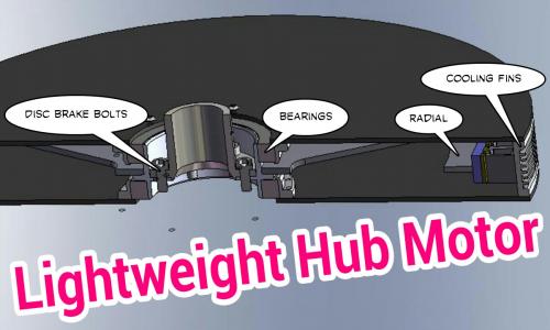
This is really impressive.
http://endless-sphere.com/forums/viewtopic.php?f=30&t=57371&start=275
Being a radial design helps overcome the "bearing slop" problem associated with an axial flux design.
In radial design a certain amount of bearing wear is okay because side-to-side wobble is less worrisome.
Cooling fins on the exterior makes this a cool running motor. (good)
Mounting to the brake disc assures a firm base. (cassette mount optional)
Bearings on both sides reduces wobble.
It's all "very conservative" stuff... and it will require some excellent fabrication skills... but it seems very possible.
This could replace both the Mid Drive and the old "Anchor Weight" (25 lbs) Hub Motors.
The "future" might be making the "past" better.
.
If the overall problem is that electric motors run most efficiently at high rotational rate. And, in the context of a light electric vehicle that is problematic due to both the desire for variable speed control and "uphill" climbing conditions. Then, wouldn't the solution be to use variable gears? Yes. Already covered I know, with among other issues being cited is the need to manually change gears. So, why not borrow a solution from ICE scooters, on one side of the rear wheel have your human power drive train (variable gears optional), and on the opposite side have a scooter style Continuously Variable Transmission (discs that spread or close by centrifugal force according to rotational rate on each pair of discs thereby providing a variable circumference for a belt to rotate on). The two overwhelming problems that would likely be cited with this solution is that, in a ICE situation, a clutch is needed for shifting to/from forward, neutral, and reverse, and that there is a certain inefficiency concerning the friction in this scenario. The first concern is negated by using an electric motor which can shift to/from forward, neutral, and reverse electrically, and in most cases light electric vehicles only move in one direction (forward) under power, again not a concern. As two the second concern, friction losses become large only when it is expected to carry/transfer large amounts of power, you cannot honestly consider 250-750 watts a lot of power, and as losses would also be a percent, they would not be likely to amount to much loss overall. This would probably overall increase efficiency and hill climbing capacity, all done automatically with infinite variability. Of course, my statements have no calculations, research, or personal experience by me to back them up so that does need to be done by someone, possibly me eventually, probably someone else sooner. Thankyou.
With a hammer, a chisle can be made. With a hammer and chistle, files can be made. With hammer, chisle, and file anything else can be made.
Kaishan k500w retired, Merida TEV500 on indefinite sabbatical, currently using a Currie E-zip Trailz.
.
I was toying with similiar ideas way back in the thread.
.
.
Everything I came up with had efficiency losses that were not very good.
.
I was thinking of something more along the lines of this:
Here is also a Wikipedia link: http://en.wikipedia.org/wiki/Continuously_Variable_Transmission
With a hammer, a chisle can be made. With a hammer and chistle, files can be made. With hammer, chisle, and file anything else can be made.
Kaishan k500w retired, Merida TEV500 on indefinite sabbatical, currently using a Currie E-zip Trailz.
.
You know about the NuVinci right?
That's a CVT that's been around a while. The problem with most CVT systems is that they tend to be heavy and waste energy in the form of heat because there is always some sort of slipping going on.
.

.
The D-Drive uses dual orbital gears and so there is no slipping. In order to vary the speed of the output a secondary input causes the orbitals to rotate forwards or backwards.
http://www.gizmag.com/steve-durnin-ddrive-d-drive-infinitely-variable-transmission-geared/15088/
...I find that very interesting because you REALLY get a CVT without slipping.
The D-Drive could deliver maximum efficiency in the primary drive and then use a smaller input power that is less rpm sensitive. Step motors seem ideal for the secondary.
----------------
Update:
http://www.gizmag.com/d-drive-redux/15120/
So it's not possible to run the control shafts using a small electric motor as we said in the video - in fact, the engineering report is quite clear on the fact that the 'control' motor needs to be just as powerful as the 'input' motor: "Our designation of 'Input' and 'Control' shafts in this report is arbitrary in that both would conventionally be used to provide power. There is no inherent character of the mechanism that requires the input to be the dominant power-providing element. The torque provided by the control shaft will typically be of the same magnitude as the torque provided by the Input shaft... the Input and Control should be considered as parallel power paths rather than as 'power ' and 'control' elements respectively."
...I was afraid of that.
It doesn't necessarily rule this idea out, but only one motor operates at optimal rpm all the time while the other has to work well across a wide range of rpm. What's worse is they both require the same overall power.
The good "old fashioned" (to me) multi-speed mid drive is hard to beat !!!
Maybe a super high tech ultra thin disc shaped hub motor could show an improvement, but that remains to be seen. That's all going to come down to successful fabrication and materials. (hard to do)
.
The searching (and waiting) continues...
The "Ratchet Gear Porn" is looking as the best alternative at this point, With a ratchet you concentrate your force into a small space and gain a lot of leverage through gear reduction. It's really the only alternative I've come up with.
.
.
Was reconsidering this idea.
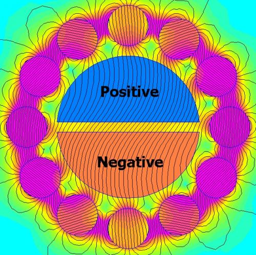
If you rotate magnetic cylinders configured as a Halbach Array they create either a rotating field or if the magnets rotate a stationary wave.
Previously I had calculated for a mid drive configuration which would create a narrow width, but this seems better for a rear hub.
.
.
The weight of the copper coils is concentrated in the center and there are air gaps around the magnets so cooling is good. Rotational inertia is low because the spinning magnetic cylinders are lighter than a silicon steel shell might be. There is no "switching" of the electric field because the flux rotates around the field mechanically, so there is no electrical rpm to consider.
.
.
Single Reduction Mid Drive
A very simple idea...
Replace the larger front chainring with a 300 tooth gear made of a non-metallic material (plastic) which will reduce noise. Add a 3000 rpm electric motor with a hardened steel 10 tooth gear.
Freewheels are optional, but probably a good idea. (eventually)
By using a combination of plastic and steel for the gears you encourage the larger gear to wear out more quickly than the smaller. Maybe every 10,000 miles you might need to replace the plastic gear which is an easy maintenence item.
Chains have been tried, but at these speeds a chain generates too much vibration and noise, so this gives a simple solution that avoids the usual pitfalls. It would be impossible to have a 10 tooth to 300 tooth chain combination, but with gears it's possible. Final gear reduction ratio (1:30) will bring a 3000 rpm motor down to 100 rpm which is right where you need it to be. The plastic gear can be fairly wide (1/4") and that increases tooth strength. Excess material can be removed in ways similiar to ordinary chainrings.
The most critical aspect (technically) will be the creation of the 300 tooth plastic gear because it has to be strong and perfectly shaped. Mounting needs to be done in such a way that it's impossible for any excess gaps to exist between gears. In the beginning it might be wise to avoid freewheels because they would introduce such gaps.
.
.
A Double Helical Gear design would increase strength and also allow for a freewheel because side-to-side sloppiness would be less of a problem. Assuming you make the large gear of plastic it's nothing but an alteration in the molding. Cutting the smaller gear in steel is more difficult however. This will further reduce noise.
Calculation:
Assume we want a 40dp spur gear. Also we want 300 teeth:
Pitch Diameter = Number of Teeth / Diametrical Pitch (dp)
Pitch Diameter = 300 / 40
Pitch Diameter = 7.5" ...which is the size of a front chainring.
...such fine teeth might be unworkable, so you would have to find the limits of practicality.
.
A nice website to do the Spur Gear calculations:
http://www.doov.com/cgi-bin/tgc_spurgear.cgi
.
.
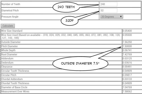
In this scenario we use a 240 tooth 32dp gear. The small gear is reduced from 10 teeth down to 8 teeth which might be questionable. Final ratios are the same and size is the same, but the teeth are bigger and so more likely to handle the load.
.
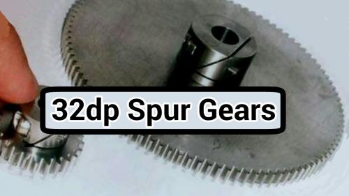
...I'm pretty sure those are 32dp teeth.
For a first attempt ordinary steel spur gears seem to make the most sense and they can be custom made at what (we hope) is a reasonable price.
.
Had another idea...
.
.
The idea would be to use two motors and have rubber wheels on them that grab the rim where the brake pads normally grab. You then set up a clutch cable and mechanism so that you must either engage or disengage the clutch to get contact. (probably engage is better)
I'm not sure if this is the most efficient idea... but it would be a heck of a lot of fun because you can crank the throttle wide open and then slip the clutch, which is a way to get a temporary reduced gear ratio.
Just on the basis of fun it might be worth doing.
If the clutch is disengaged then it freewheels... if engaged regen.
Hmmmmmm... maybe a true clutch type action is best.
Ah ha! Got it... use a low motor current setting with the motors so you can't crank the throttle and get too much heat if you were at a stop. That way if you need power you have to slip the clutch to build some rpm which will get you power. This will result in heat on the rubber wheels and NOT the motors, which is good. :)
Essentially any clutch like design is interesting, but manual rather than automatic. In past posts I've done a lot of eddy current hysteresis clutch ideas, but there are times to slip the clutch and other times you shouldn't.
Unfortunately some states actually explicitly ban manual clutches, so that's a problem.
.

.
...there have been abundant attempts at "friction drive" but they tended to rub on a tire that is exposed to dirt and water. By moving the contact back to the rim (from both sides) you avoid the dirt and water problem. Also, with the clutch action you add some fun. You also aren't going to wear out your tire due to motor contact.
Mounting the motors below the rim actually makes more sense because you avoid tire clearance issues. I think a wishbone type linkage for each motor would be ideal. (two pivot points in a wishbone will be stronger for the same weight)
.
.
...I'm thinking maybe orienting the pivots so they are on the upper chainstays and have the motors back behind the pivots.
.
.
As with most ideas... "somebody, somewhere" has had it already.
This was from France.
http://www.cybien.fr/
.

.
Our main features:
- Motors or automatically releasable on demand
- Low weight of the complete electric bike (from 16.90 Kg)
- Autonomy in hilly courses (70 to 150 km)
- Sports range (electric bike S3, V3 and carbon models)
- Comfort range (electric bike models C2 and D2)
- Designed and manufactured in France, they are sold live for a very competitive cost.
-------------
A very professional product in my opinion. It resolves the whole geardown problem by using the surface of the bicycle rim. The efficiency is going to be good because the motors spin at high rpm and the contact is smooth, but probably with good grip.
Nice.
.
.
This goes a step back and rubs against the tires sidewall. I suppose the tire and sidewall both wear out normally anyway, so as long as the wear rates are similiar it should be okay. Flex in the sidewall will reduce efficiency compared to the custom rim of the Cybien.
The Cybien reports impressive range and durability. Reports of 10,000 km without mechanical failure are believable because there are no gears to wear out. Range of 100 km per charge.
...this whole design concept is sound.
I'm glad I "invented" it. (kidding)
.
.
https://www.google.com/patents/US3915250
SUMMARY OF THE PRESENT INVENTION In the present invention a pair of substantially identical electric drive motors, each having a drive roller mounted on the end of its shaft, are mounted one on each side of the rear wheel of the bicycle. The tire is pinched between the two drive rollers by a tension bar which can be adjusted to provide a spacing between the rollers that is slightly smaller than the thickness of the tire. This pinches the tire slightly between the two drive rollers and employs the pneumatic resilience of the tire itself to provide the desired frictional drive between the two rollers and the tire. Since the only force between the rollers and the tire is provided by the link between the rollers themselves, the two forces against each side of the tire are exactly equal, and therefore the frictional drive of both rollers must be the same.
I'd prefer a clutch and I think using the tire sidewall is less efficient, but the patent for the basic idea goes back to at least 1975.
.

.
.

.
.
The next obvious progression is to mold actual teeth into the rim so that you have a:
"Geared Rim"
One might use a single motor with a slight gear reduction.
Side-to-side gears are setup so that normal rim deviations are accounted for with a free floating mount. Since the rim width can be assumed to remain constant you can have a preset gap which guarantees proper gear contact.
This will not permit clutch like behavior, but it should be possible to stop the bike and disconnect the motor if you don't want to use it. It might be okay to disconnect and connect while riding, but probably not under power.
Efficiency should be very good and the potential to use a single motor has it's advantages.
--------------
Another variation might be to put the gear teeth on the inside of the rim on just one side. You now have an even less complicated design requiring a single motor and very high efficiency.
As long as the rim remains true in the round direction the side-to-side deviations are not a big issue.
This will require a specially built rim, but a DIY design could be done by bending a linear track and then bolting it to the inside of the rim.
.
.
Features:
• CNC Machined Billet T6 Aluminum Motor Can
• High Purity Copper Windings
• 4mm Bullet Connectors Pre-installed
• Powerful Sintered Neodymium Magnet
• Precision Engineered for Maximum Energy Conversion
• Water Cooling Jacket Pre-installed
Specs:
RPM/v: 620kv
Winding: 2.5Y
Max voltage: 37V (10S)
Max Current: 105A
Max Watts: 3050W
Resistance: 0.03ohm
No Load Current: 0.7A
Can Diameter: 39mm (actual motor diameter)
Can Diameter inc. Water Jacket: 49mm
Can Length: 84mm
Shaft Size: 5mm
Weight: 508g
Motor Connector: 4mm bullet plug
.

.
High Pole Count vs Low Pole Count
For many years I've dreamed of a mid drive that combined a very high speed low pole count motor and a complete transmission system with multispeed gearing. To my knowledge it's STILL not in existence yet.
The debate really comes down to high pole count vs low pole count motor design.
There is a finite "Electrical RPM" no matter what you do so:
"Pole Pairs" * "RPM" = "Electrical RPM"
From a design perspective you trade space for speed... higher speed can be smaller (diameter) and that can translate to being lighter.
Racing gasoline motors have attained speeds of 15,000 rpm and yet our ebikes tend to run at around 4,000 rpm because our low tech fabrication skills have prevented us from taking it any further.
But the advantages of an Inrunner motor with a lower pole count and water cooling is rather obvious. The compactness of the design allows the magnetic flux within the motor to be more concentrated and since the faster you switch "per magnet" the more power you will produce "per weight". Electrical RPM tends to limit our ability to max out our magnets when pole counts grow too large, so the bigger things get the more weight we waste with excess iron.
So I can imagine this "Utopia" for ebikes with a compact high speed, low pole count, multispeed, water cooled, inrunner, dual freewheel mid drive.
But just don't ask me to build one. ;)
Any hungry newcomers with high tech resources up to the challenge?
.
Hi, I found this thread by "accident" yesterday.
You deserve congratulations for doing such an excellent job with explaining all those ideas.
Regarding your Clicker idea, with the solenoid driving a ratchet, I think that the idea could be much more easily implemented by using a One-way clutch instead of the ratchet & pawl. Those clutches are also called Sprag clutches, and they come in all sizes and forms.
See here:
One-way clutches
Those clutches are completely silent, and they do not require a definite stroke for advancing. The slightest movement is enough to make them engage and transmit drive. And in the reverse direction, they slip easily without much drag.
One of those could be installed on the shaft that holds the left pedal (I forget the name ...). Then, by attaching a lever to the outside race, you link your solenoid to it via a small arm.
To augment efficiency, the best thing would be a bi-directional solenoid like you're proposing, to solve the problem of residual magnetism, but also to be able to get drive on both strokes of the solenoid.
The way to do this is to put 2 One-way clutches side-by-side on the shaft. I won't try to make a drawing it because it would take me hours to do the same thing that you do in minutes LOL, but it is set-up like this.
When viewed from the side, the first clutch is linked to the solenoid as I explained above. Let's say that its actuating lever is vertically going up, and the small link attached to it goes laterally to the solenoid.
The second clutch will then have its actuating lever going vertically DOWN, and from there the small link goes to the solenoid.
On each stroke of the solenoid, regardless of if it is a Pull or a Push, the 2 clutches will rotate in an opposite direction from each other (because one has its lever going UP while the other has its lever going DOWN), and one of the 2 clutches will be driving while the other will be freewheeling.
I'm hoping that my explanations are clear enough, and I'm sure that you will then make a nice drawing of this ;o)
Cheers
I like your idea Altair.
Unfortunately I just double posted... to the last post...
(oh well, use the post for an item description)
.
.
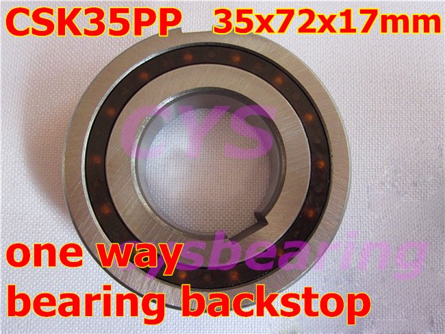
CSK35 One way Bearing Sprag Freewheel Backstop Clutch VXB Brand
Features
Inner Diameter: 35mm
Item: CSK35 Bearing
Outer Diameter: 72mm
Quantity: One Bearing
Torque: 140 N.m
Type: One-way (clutch) Bearing
Width: 17mm
...140 Nm is very impressive.
.
.
I like your idea Altair.
The funny thing is I actually used a sprag clutch on my ebike, but after some time (and because of power levels well above it's design limit) the sprag clutch wore out and I replaced it with a fixed drive.
What is truly beautiful about the idea is that a sprag clutch can be extremely quiet.
Simplified version might look like:
.
.
The crudeness of the big ratchets and all the noise associated with them does discourage doing the idea, but switching to the appropriately sized (for power) sprag clutch could allow the ratcheting behavior that is needed.
Very nice... will have to think about it more, but I think you've made a big leap forward with the idea.
Having two solenoids makes sense, but having one and a spring is easier.
Compared to all the exhaustive technical skills to produce high rpm and heavily geared down mid drives the simplicity of a sprag clutch and solenoid seems like a refreshing relief.
Someone needs to do this eventually. Hmmmmmmm... at present I don't have any workshop to work in, but that could change.
.
Hi safe,
the problem I see with a solenoid-driven crank is that it is basically a fixed-torque drive.
If we look at a normal electric motor, when variable power is applied to it, it will actually produce more or less torque.
Then, the resulting rotation speed will be inversely proportional to the friction/drag that the motor must overcome. So RPM will vary smoothly and the driver has time to adjust throttle position to obtain the acceleration/speed he desires.
With a solenoid-driven bike, if you vary the throttle, you can vary only the frequency of the strokes, because it would be difficult to vary the "strength" of the solenoid. Too little and it doesn't move, and more than enough doesn't make it move any farther... The solenoid is always at full power, basically.
So you are left with a drive that is very sensitive of the throttle position. The pulse rate, and hence the bike speed is directly affected by throttle position. Of course, it is possible to add some filtering and delay to the control signal but I don't think that would be enough.
I think that a good electric drive must give the feel of a gas-powered car. If you set the throttle at a particular position, the car will accelerate less & less strongly while the speed will increase more & more. On deceleration, it's the same. On a street bike we cannot have that deceleration effect because of the freewheel in the drive. The motor cannot decelerate the bike.
It could, by removing the freewheel, but then would it become a "motorcycle"? ;o)
I'll have to think about this...
This would be for a Mid Drive.
Pedal speeds are narrow... usually from 70 rpm to 100 rpm.
Very rarely does one pedal at, say, 20 rpm, because your legs prefer about 85 rpm.
So the idea would be to optimize everything for about 85 rpm.
Final gear ratios are determined by the derailler.
------------------
I was also thinking you could set up the solenoid with a spring at both ends. That way you can sort of "bounce" back and forth. Would have to play with some ideas. But using a magnet as the cylinder you should be able to make power in both directions and the two springs would "contain" that energy. There would be an empty "unsprung" center area which is driven by magnetic forces and the outer extremes are assisted by the springs. The springs effectively "recycle" the rebound energy that would normally go to waste.
.
.
What I really need to do is some FEMM simulations.
.
.
The magnetic force "powerband" of a solenoid like device is alterable, so with some work you could create the powerband you want.
The advantage of concentrating all you power into one spot is compactness and usually efficiency. But these things take some time to figure out.
The Sprag Clutch idea is great and products can be purchased for about $20. 140 Nm is a very large torque for a Mid Drive, so it would be very durable.
.
.
This is a further simplification.
The spring would bring the system "out" of alignment. (free direction)
The horseshoe electric magnet with two coils brings everything "in" alignment and is the power stroke.
There is no friction compared to a solenoid.
.
Good idea, safe.
The solenoid would be in fact a rotary actuator.
As happens often with solenoid setups, you have to fight a spring.
However, with a bi-directional solenoid, or bi-directional actuator, you don't have that inconvenient.
I've made a primitive drawing of the bi-directional system with 2 sprag clutches.
When the red clutch drives, the blue one is resetting, and inversely.
Well, apparently, my upload doesn't seem to work...
Pages