Hi All-
Thanks to the oodles of great information (with special thanks to The Laird and to Ben Nelson and his videos) I am the proud owner of a converted 2007 Vectrix.
When I bought the scooter, there was a Givi 52 Topcase attached. I am very interested in adding these LED lights ( http://www.twistedthrottle.com/admore-lighting-led-kit-for-givi-e52-topcase ) to increase visibility in addition to updating my headlamp. I wonder if anyone has connected an accessory light kit and if so, where the heck do I tie into the existing lights?
Thanks in advance and apologies if a stupid question. I'm a just a learnin'.
Doug


VX1 appears to be using some VERY odd voltages for the rear lights, so I am fairly certain you will not get much joy out of that LED kit as it is meant for the regular 12V DC that is standard on motorcycles and passenger cars nowadays.
My rides:
2017 Zero S ZF6.5 11kW, erider Thunder 5kW
I recall reading somewhere here that the rear lights cluster works at 4v...
I think the 4V is just on one of the components ,but the low resolution of Galago's circuit diagram does not make it easy to read:
The rear LED lighting feeds are not conventionally wired as the switches connect directly to the Interface Control Module (ICM) which processes the input signals and then switches the required current to each of the lighting/indicator circuits, some of which are wired in series between the front and rear mounted components (Front and rear left hand indicators, front and rear right indicators, and the front sidelight and rear licence plate light).
I seem to recall that the lighting circuits are supplied with a constant current feed instead of the more conventional constant voltage supply, so it might be possible to use four low voltage relays wired in series with the rear light, brake light, and L&R indicator LEDs to switch a 12V supply taken from the luggage compartment switch to feed the top box LEDs, but the four relays would need to be of a suitable voltage and resistance to operate at the same current level as the existing LEDs.
I suspect that some form of in-line current sensing electronic device could be used more efficiently to possibly switch power transistors instead of relays with much less power consumption and also less chance of triggering any bulb failure warnings in the Interface Control Module (ICM) (if they exist).
It would not be an easy installation and could possibly result in damage to the ICM, so it might be better not to mess around with the wiring.
The rear lights on the top box could be connected to the 12V feed for the luggage compartment light so that they came on with the ignition for better visibility from behind (although they would also come on while charging too) but the brake lights and indicators would definitely require a lot more time and effort and some more advanced electrical knowledge.
Alan
Thanks for those informative responses. It seems unduly complicated, so I am going to buy some 3M Diamond grade reflective tape and put that behind the red clear plastic and be done with it.
Additional todo's:
1. Better side mirrors (Wider view, etc). Any suggestions?
2. Look for an inexpensive connector to the Leaf BMS that will let me manually measure the voltage in each cell without opening the battery compartment. I don't want the expense of a leveler, but I sure would like an easy way to check that the cells are not drifting. I don't mind checking them with a voltmeter by hand because I don't expect to have to do it often.
Input to the rear taillight is 12V - it has an internal circuit board to supply the LED's.
The indicators are different, they are wired in series (front + rear) and supplied by a constant current driver on the BCM - so not 12V.
As for measuring the leaf cell voltages - I've used 5 cell-log8's with a special discharge balance board I designed (they drain the cells unevenly if you don't use this). Its nothing complicated, just uses opamps in a voltage follower mode (unity gain with high input impedance resistors).
The feed to the rear tail light and brake light appear to be current limited too. According to Mik's pictures the rear tail light is just 13mA @ 0V and the brake light is 163mA @ 0V.
It would be interesting to know what the current and voltage is under normal operating conditions for the tail light and the brake light feed wires as 13mA @ 12V = 156mW, which hardly seems enough to power 13 LEDs.
Alan
Bluestreak, I purchased the LEAF 18 cell package from Hybrid Auto Center, so I have the same orange cable and the end connector as in these photos. I was hoping to attach one connector that I could pull through a hole in the back of the battery compartment cover to the underseat storage, giving me easy access to a voltmeter or a switchable connection to something like the Cell Log multicell Monitor . It appears that with the setup you have shown here that it is necessary to change the connectors, which I am trying to avoid. has anyone seen a connector extension?
Like this?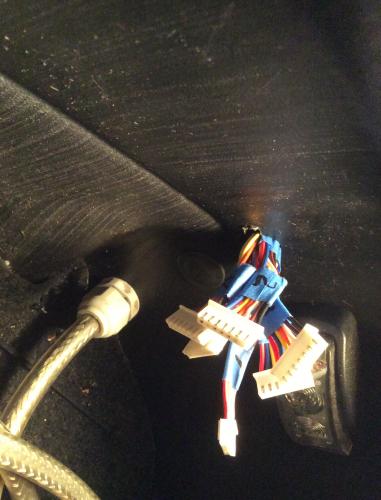
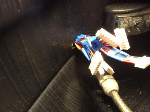
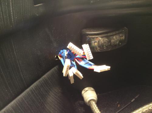
YES, just like that!
What do these connect to? Can I check the voltage for each of the cells through this setup? I don't expect to have to rebalance the cells, but it seems imprudent or perhaps even reckless to not even *check* them now and again.
These connect to your cell checkers and you can balance the leaf cells through these connectors.PS yes you can check the voltage through these but the best way it to buy a cell checker and it will show the voltage of (6) cells that's 3 moduels at a time.
That looks like it will do the job. Can you share details on what you used for cables/connectors and cell checker? Also, how in the world does one hook up the wiring?
HI KINCHIP, go to EBAY and type in (CELL CHECKERS) and (type in JST connectors) and you will find just what you want. NOW as for as how to hook up the leaf BMS wireing harness that can be quite a challenge if you don't have skills to sort this out.BTW where are you located?.
Did you read through this thread (maybe look at the current last few posts for the connector info)?
http://visforvoltage.org/forum/13767-nissan-leaf-modules-li-conversion-questions
And did you check "Ben's Repair" thread or his blog 300mpg.org? Ben's got great videos too.
Careful with these connectors to the BMS due to the high voltages and currents! But conceptually it is simple - just connect the free ends that come out of your Leaf's harness to the free ends of the JST connectors that BLUESTREAK mentioned. I used smaller sized 10-cell RC connectors than him, which take less space but are a bit less sturdy. Yes, you can check the voltage between any two terminals through them with a voltmeter/miltimeter under the seat: from a half pack to the entire battery if you want. As someone else mentioned, do not leave RC style volt meters directly connected to these leads permanently or even for a long time - they use some electricity and will disbalance your cells. Plus the cheap ones as I used (link in my thread above) were not very accurate, so the readings are mostly worthless anyway. I've been using a regular multimeter to measure the voltages by had every once in a while, trying to measure each cell every time so that I don't disbalance them. I only do it after a deeper discharge and on a fill charge too so I can confirm that no cell is too discharged or too full. You have to do it immediately after a ride, as the cells will recover somewhat and the measurements might not be reliable if you let them sit for a while first.
When not in use, my connectors are wrapped in a small protective pouch and just hand in the corner of the cargo area, out of the way. You want to protect them and avoid any chance of shorting them with something in the cargo area or if the wires would rub through due to vibrations or pressure.
And you can rebalance any half cell or a group of cells, if needed via these connectors too.
Look at my post here for images: http://visforvoltage.org/forum/13767-nissan-leaf-modules-li-conversion-questions?page=4#comment-73747 . Pasting here again.
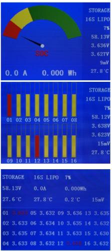
Anybody has checked this Rc 16S BMS balancer with color display? With 3 of these in series can be covered the entire battery (14s+12s+12s):
http://www.chargery.com/BMS16.asp
looks full featured, displays hi low level, can program alarms and activate relays.
THANKS "R" THOSE ARE SOME NICE ITEMS YOU FOUND.
HI fellows I KNOW THIS MAY BE A LITTLE LATE BUT i JUST ADDED AN LED lights TO THE TRIKE FENDERS ON MY SON'S VX4 VECTRIX(NOT COMPLETE YET) AND HOOKED THEM TO THE REAR BRAKE LIGHT HARNESS which IS (12VOLT) AND IT WORKS GOOD.PHOTOS WHEN TRIKE CONVERSION COMPLETE.I added (4) led lights to the rear fenders and each light module has (4) led's in them. COOPER.
I have another question about the led turn signal bulbs are they (12 volt bulbs) I am asking about the bulbs only not how muck voltage the IMC give out to the system!
Are'nt they 5V DC leds? I believe they do not have a 12V-5V step down converter inside. If you feed 12V to them they may fuse.
According to the wiring diagram in the manual, the front and rear indicator LEDs are fed in series with a 4.4V supply (2.2V across each indicator light unit) but only when the circuit on the ground return is closed. The feeds to the front indicators are marked "4.4V When Lamp is ON":
The diagram also shows a current limiting resistor between the switch and Ground connection on the return circuit from the rear indicator.
It might be possible to use a couple of miniature 3V relays and suitable series resistors connected in parallel with each pair of indicators to switch a 12V supply to "a lot of led lights", but you would need to make sure there is sufficient current available from the Interface Control Module to actually energise the relay windings, and without reducing the brightness of the original indicator LEDs too much.
The resistor fitted in series with each of the relays would need to be at least half the resistance of the individual relay windings to operate the relays at their correct voltage.
Alan
Thanks fellows for the infomation. I did do an experiament with a 12 volt led,I pluged one into the front turnsignal light and plug one into the rear turn signal light, the front 12 volt led module (each module has 4 leds inside) burns full-brightness but the rear leds burns dimmer. so it must be getting 12 volt from the controller. but I am afraid to hook 12volt directly to the vectrix turn signal lights.
Original turn signal leds will burn at 12V...
The directional output of the ICM is a current source designed to provide about 500mA. There is a driver for each side (front and rear) so basically 2 LEDs in series. It is not a voltage source, and the voltage you see at any LED terminal depends on that LEDs characteristics. The voltage will be whatever it needs to be to drive 500mA thru the LEDs. This method controls the brightness regardless of forward drop in LED.
Is this what you had in mind ?
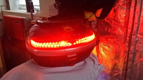
This simply connects to a spare 12v supply - no need to splice into any wiring and it is easily removable via a water proof 12v connector under the top box mount. Let me know if you want more information and I'll take some more pictures for you.
Allan
Electric traction is the future.
Thanks ALLAN I have it all worked out now. (1st.) I tapped into the rear tail light and brake light harness and ran the wires to the fenders of my son's trike and it works perfectly.(2nd) i have added a seperate 12 volt (battery power source) and changed out the vectrix 4.4 volt led's and added 12 voly automobile led's and added a 12volt motorcycle automatic turnsignal module and added a new handelbar momentary pusch button switch ( with this set up I will no longer use the vectrix turn signal switch) now my turn signal lights have running lights at all times and flashing turn signal when you push the left or right momentary button switch and they will self cancel @ 7 secounds or 20 secounds or 70 secounds depending on how many secounds you hold down the momentary button (1 sec. 2 sec. or 4 sec.) I will post photos when I get my son's vectrix trike finished.
yes please!
where is this 12V spare connector placed?
HI "R" I think he is saying that he has added a small 12 volt battery or he is using the (cooling fans 12 volt supply). since he has leaf cells the fans are not needed.I am using a small 12 volt battery to supply power for now since I still have the old NMHI BATTERYS in my son's trike and have not installed any new software, later I will use the cooling fans 12 volt power to power all my extra lighting since all my added led's only draw (.95 amp)
This 12v battery only serves to power the running lights, right ?
Here in Portugal, normally the extra lights in the topcase are used as brake lights.
Since the signal for activating the brake lights are CANBus driven, one can't use the topcase lights as brake lights, right ?
HI ZEUZ, on my sons trike the extra battery 12 volt supply runs the extra side running lights and my new turn turn signal lights only. later when I install the new software from the (LAIRD'S TEAM) I will use the cooling fans power circuit. the rear running lights and the brake light circuit can run extra rear running and brake lights but may be limited on how much amps this circuit can produce.if it produces (5 amps) like the cooling fans produce you can run all the extra brake lights you want. hope this helps.
ZEUZ, The only 4.4 volt lights are the original turn signal lights of which I have changed to 12 volt automobile led lights and run them off the extra battery circuit I installed, I just unplugged the original vectrix 4,4 volt harness and removed the 4.4 volt led bulbs and replaced them with a new harness I made and now every thing is 12 volt.(BY THE WAY) the rear running and brake lights have always and still is 12 volts.
Pages