.
In the previous post I looked at the "extreme" of 19 Phases. That's probably beyond practical thinking, but it does show how resource utilization can be pushed as high as 95% which is a huge jump over 3 Phase with it's 66%.
9 Phases is split into opposing coils to make 18 electrical coils configured in whatever manner you choose. (the animations are more about theory)
With 9 Phases this means 8/9 of the time a coil is in use or 89% which is "good enough".
Using 20 magnets where for every magnetic flux revolution you pass two magnets means that the magnetic flux rotates 10 times faster than the magnets.
This would probably be the maximum optimization you would attempt.
Normally we think of the physical shape of the motor first, then we think about how we can best adapt our understanding of copper-to-iron interactions to achieve the most efficiency we can get from the desired geometry to create the maximum magnetic flux.
So then I thought... what if we designed for efficiency first?
Well, you would want 100% of the copper to actually create flux in the iron (silicon steel) so the ideal would be to make a pancake of iron-copper-iron-copper in order to get all the current translated into flux.
The image shows what that looks like.
What is interesting is that the entire chuck of silicon steel gets activated with no more than a watt of energy and it's something like a pound of silicon steel.
Could one build a "flux capacitor" as a separate component?
Well more or less "yes" you could.
Then you start to think about compartmentalizing the function of "flux creation" and "flux usage" as two separate functions.
You combine the Cycloidal Drive concept with an electric motor.
In this case it's 6 Teeth -> 7 Teeth, so only a slight gear reduction, but if you increased those numbers to something like 20 Teeth -> 21 Teeth then you have a 20-to-1 gear reduction built into the motor itself.
Also the more you increase the base number of teeth you also reduce the difference in diameter of the gears which means there is less vibration and it also reduces the air gap variability.
Friction is only the gears themselves touching each other. You should be able to not need a bearing because the side to side movement could be controlled with another set of magnets on either side of the motor magnets. The center gear would run on bearings however.
I'll have to do another animation with higher numbers of teeth. This was just so that I made sure the math is right. (there was a slight error that was corrected half way through)
You would have to keep the PM "wobbler" (no longer a rotor :-) from rotating, though. I doubt the magnetic attraction would be sufficient to keep the "wobbler" from rotating once the gear is asked to drive a bike.
My rides:
2017 Zero S ZF6.5 11kW, erider Thunder 5kW
The magnet rotor wouldn't rotate much. When the coils are activated they want to center the rotor node onto a fixed location and that's actually what drives the motor shaft. Rotation is prevented... but that's actually where the torque comes from. (so it's actually the process of the rotor aligning itself that generates the torque).
Since the magnets only wiggle in a small circle (defined by the ratio of gears) when you got to something like 23 -> 24 teeth (23-to-1 gear reduction) the wiggle will be small and all you need is something to keep the magnets from side-to-side movement. The side-to-side magnetic polarity oscillates only slightly and never changes direction.
So you could place "guide magnets" on the sides of the magnets that drive the motor.
It might be like magnetic levitation... you could go with a Halbach Array, but I doubt it would be necessary. The nice thing is this aspect is frictionless.
I'll have to post some more (it's still a new idea) but in FEMM there is a natural cogging behavior so that when you turn off the wiggle power the rotor stays where you left it. The magnetic flux on the opposite side of the teeth contact area is the highest point of magnetic attraction which is good because we want the teeth to be firmly pressed together.
The issue I'm actually looking at is friction right now.
The problem with all these fractional gearing solutions is that the gear teeth approach each other at weird angles that force the teeth to generate too much friction as they slide past each other. I'm currently looking into combining the benefits of a planetary gear in the center which would "skip over" a tooth each wiggle but then alter the skew angle of the involute teeth to compensate for the advance. In the animation imagine shifting the blue line to a slight offset. If this thought process proves viable it might offer a better cycloidal drive solution which might be stand alone. (likely becoming a separate line of thought)
.
.
One other thing is that I realized you can reduce weight on the wiggle rotor with a more conventional magnet configuration (magnets pointing in and out) and if the number of magnets matches the gear teeth number you can reuse the steel in the teeth for flux transfer. Since the magnetic flux never fully reverses it should produce little heating. The back flux path doubles as the gear teeth.
How might this motor be controlled? I have no idea at this point.
...this would be the same but with one extra tooth added and a change to a Cycloidal orbiting pattern.
I'd want to play with the gear ratios and tooth angles, but the idea would be to get the high gear reduction without excessive friction due to teeth sliding against each other.
After looking at the "friction question" with the planetary gear combined with a circular cycloidal orbiting pattern it started to dawn on me that things are different than I thought.
Circular orbiting has less friction than orbiting the entire outer gear and forcing gears of different tooth counts to grind against each other.
So I went back to a simple 18 tooth - 19 tooth cycloidal:
.
.
From this I reduced my effort by just doing a couple of teeth:
.
.
What becomes apparent is the friction isn't that bad.
Circular orbiting (around a single tooth) seems better than orbiting the entire gear.
.
.
With the circular motion of the outer orbit being really tight it opens the door to a shape that might optimize contact to only a small amount of friction. This is done with watches that use Lavet Motors and need high efficiency, so it looks pretty good. If the outer gear was made of all cam followers (with needle bearings) that would be optimal.
There is also a difference between clock gearing and circular cycloidal gearing because the contact occurs on many gear teeth as the outer gear orbits. In this example 18 (inner) and 19 (outer) gear teeth alternate one at a time applying pressure to produce torque. This means each point of contact can be controlled to occur only in favorable friction situations. You can shape teeth so that once the angle gets weird it bends away.
From what I've been able to figure out it looks like the best angle for the teeth is roughly square.
Contact occurs along a flat curve and only deviates slightly as the teeth pass by each other. This is good news because it should make the teeth durable. By changing the shape you can actually limit contact area and the duration of contact.
Additional contact would be needed in order to center the gears in relation to each other. Having the contact resting on the inside edge seems to make sense.
So there would be two separate contact areas, one for torque and another to position the outer gear in relation to it's intended centerline offset.
In an electric motor this inner resting place would prevent the circularly orbiting set of magnets mounted on this 19 tooth outer ring from colliding with the coils on the opposite side.
The behavior here is very unusual and different than spinning cycloidal gearsets.
An important point is that all torque ends up going through just one tooth at a time. This is great for reducing friction, but means the individual tooth must be able to handle the full torque of the motor. (that might be a problem)
First I moved the coils inside rather than being outside, so I effectively made this an Outrunner of sorts much like the RC motors.
Next I moved the magnets inside and buried them deep into the iron. It would be near impossible to damage the magnets due to overheating.
The outer ring of circles could be cams with needle bearings. This reduces friction to next to nothing and calms any worries about low efficiency based on friction.
The gears are 24 teeth inner and 25 teeth (cams) outer so the effective gear reduction is 25-to-1 or in other words it could spin at 2500 rpm and yield 100 rpm at the pedals.
The part that actually "wiggles" (in a small circle) is now made of one piece of silicon steel and has no attachments that might fall off. How to construct that for both mechanical strength and magnetic flux is a big question mark. Eddy currents are a problem if it isn't laminated.
Power would be generated through coils on the inner nodes. The rounded shape of those nodes actually increases the surface area and increases magnetic flux transfer.
Cycloidal motor with 48 inner teeth and 49 outer teeth giving it a built in 49-to-1 gear reduction.
This means a 5000 rpm (equivalent) motor speed produces 100 rpm output.
Note how the inner gear doesn't rotate. It goes in little circles but doesn't actually rotate. With proper tooth shape the friction should be less than with a rotating inner gear.
Okay now you are probably wondering why I'm adding porn...
Actually it's not porn, but the magnetic flux that occurs using the same frequency of oscillation (20 Hz) and current (10 A) but varying the position of the magnetically inductive element.
What happens is the Voltage Drop varies depending on the "effect" the coils have in creating the magnetic flux. Flux Linkage defines Voltage Drop.
.
.
What this means is you can "sense" where the rotor is in something like a switched reluctance motor at any time.
And with the PAS (Pedal Assist System) requirement on many new ebikes the startup problem disappears. The controller / computer only needs to send pulses of current through the system and measure the Voltage Drop to know rotor position. Very little power is used to send out these test pulses.
We know what is going on by wiggling the current and seeing how much opposition we get to doing that. More opposition (reactance) means the inductive element is centered and less means it's off center and permitting less flux.
Okay... was kind of working on another magnetic concept, but I'll look at Flux Linkage again.
.
.
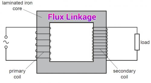
So if we looked at an ordinary transformer there is 100% Flux Linkage in a simple square path. Other than hysteresis and other losses every magnetic field created in one side will be recreated on the other side. The Voltage Drop is at it's highest because the alternating current drives a load as well as alternate the magnetic flux.
.
.
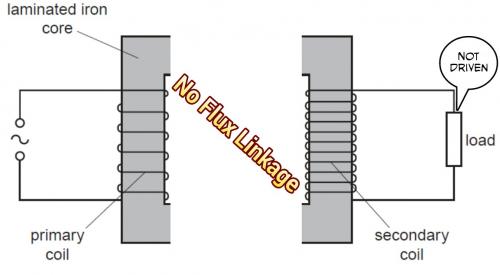
If we break the Flux Linkage you will now not get any circulation in the square path and so the load will end up not being driven. The alternating current on the left will create a magnetic flux but the path is now into air which acts as a weak flux path.
So it's pretty clear that circulating magnetic flux requires work on the part of the left side coil and that work is seen in terms of the Voltage Drop.
Extending the idea to the general case you arrive at the idea of the generic BackEMF concept which can apply to any change in field.
In short anytime you create a flux it costs you a Voltage Drop because you are doing something. Even though there aren't permanent magnets in something like a Switched Reluctance motor you still have a dynamically changing Flux Linkage. Therefore, if you sent out small "test pulses" as the Flux Linkage changed with time you could measure that to know what is going on. I think the FOC ("Field Oriented Control") chips do something like this in their "learning mode". They will send out testing pulses and see what comes back and from that they can derive the abstract motor model that then is used to drive it.
One trades voltage for flux and then flux for torque.
.
.
With a small efficiency cost in these "test pulses" you could control a PAS ("Pedal Assist System") without needing any more than a Single Phase and without actually using sensors. The degree of how far you could perfect this is not clear, but the FOC chips have gotten really good these days.
I ran some simulations in a simple Flux Linkage situation and compared the Maximum Flux Linkage to the Minimum Flux Linkage and how variables like Current (Amps - A) and Frequency (Hz) effect the Voltage Drop.
Nothing unexpected.
It looks pretty linear so as you increase either the Current or the Frequency or both the Voltage Drop increases.
.
.
However it's likely linear because the Current is fairly low. If you pushed things harder or faster you would get effects related to the Hysteresis of the Silicon Steel being used.
The simple concept in all this is that whenever you create a Flux in the Silicon Steel it takes more effort to get back to neutral than if you never created the Flux.
PAS based ebikes could be made to operate without magnets and simply run a kind of sensorless Switched Reluctance setup which uses clever programming to sense position.
An important point is that you only get the Voltage Drop because you "wiggle" the current back and forth to cause a Hysteresis loss in the Silicon Steel. A constant current will not give you any valuable information. This is why you would do this as a "pulse", but hopefully not cost too much in terms of energy wasted.
When the Flux Linkage is at it's lowest the Inductance will be at it's lowest and the Delay in voltage change with time will be short:
.
.
But when the Flux Linkage is high the (apparent) Inductance is high so the Delay gets longer:
.
.
Now keep in mind how PWM (Pulse Width Modulation) actually works. One doesn't simply flood your motor with raw current, but instead you feed it "pulses" where at low throttle the pulses are few (low Duty Cycle) and at full throttle there are many "pulses" (high Duty Cycle) so this sort of thing already happens.
The trick would be to have some built in feature that would measure a very specific voltage in a tightly controlled time period. Since you could measure the entire area it could be done in some sort of capacitive side circuit that would trap the voltage rise and then report that figure rather than just the incremental voltage in some instant.
Fast rising voltage means low Inductance and less Flux Linkage.
Slow rising voltage means high Inductance and more Flux Linkage.
...in reality the Silicon Steel will behave in some non-linear ways relative to a pure inductor, but the early stages will be "mostly linear".
As the rider pedals a PAS ebike you could send out these tracer "pulses" that are as short and spread out as possible just so you can figure out what is happening. Once the controller learns what is happening it then begins to add power as is appropriate.
My "guess" is that as the rider slows down his pedal pace this will show up in the readings as being like a generator providing negative feedback. This would then signal that power would need to reduced. All this will occur at speeds hundreds of times faster than human perception.
Dave: Well, we'd be in very serious trouble.
Frank: We would, wouldn't we?
Dave: Hmm, hmm.
Frank: What the hell can we do?
Dave: Well, we wouldn't have too many alternatives.
Frank: I don't think we'd have any alternatives. There isn't a single aspect of ship operations that's not under his control. If he were proven to be malfunctioning, I wouldn't see how we would have any choice but disconnection.
Dave: I'm afraid I agree with you.
Frank: There'd be nothing else to do.
Dave: It would be a bit tricky.
Frank: Yeah.
Dave: We would have to cut his higher-brain functions...without disturbing the purely automatic and regulatory systems. And we'd have to work out the transfer procedures of continuing the mission under ground-based computer control.
Frank: Yeah. Well that's far safer than allowing HAL to continue running things.
Basically if you use electromagnetic waves inside a microwave oven you can heat water because the resonant frequency exactly matches the internal molecular structure of H2O.
All this does is take it to the next level and creates a complex set of waves that exactly matches the resonant frequency of a metal.
You can melt metal without heat using electromagnetic waves.
For those curious about the 911 Mystery this is a possible way to explain why buildings collapsed in ways that defied the ordinary laws of physics.
It seems like Stealth technology... something we aren't aware is being used. (a new weapons system possibly?)
Anyway... it's interesting because it's existence is something that relates to all the same component parts we use to create electric motors: electricity, magnetism, metal resonances and hysteresis, etc.
Practical usefulness for ebikes? Hmmmmm, not likely, but it does open your mind to thinking about these forces in a different way.
On an ebike when the motor decomposes we consider this "undesireable".
A motor based on switched reluctance alone will have three things that must be modeled in order to accurately reproduce and then control it's behavior.
Resistance - This can be learned by applying a steady constant current through the coil.
Inductance - This is the copper inductance alone and requires an alternating current or pulses at minimum to be learned.
Hysteresis - This is dependent on the shape, size and position of the rotor and stator which are made up of silicon steel laminations.
One can see the Hysteresis as a kind of "memory" because when you induce a magnetic flux in silicon steel it will leave a Remanence afterwards. This is why backEMF grows with motor speed and frequency because Hysteresis becomes more "expensive" to reverse as you do it faster.
In order to separate Inductance and Hysteresis you would have to run a variety of test frequencies to differentiate (as well as possible) what values would represent these variables. The "best fit available" would be chosen which is different than the "exact fit".
Early computer memory relied entirely on Hysteresis in silicon steel, but there are new advances in this idea of a "memristor".
This is a continuation of past Left Side Crank Motor thinking.
In this design the Toroidally wound copper coils and Silicon Steel stator are mounted so that they can be screwed directly into the Left Handed threads of a standard Bottom Bracket. There will likely need to be some type of torque bar to prevent it from coming loose as the forces seem to want to unwind it.
Another thought is to move the left Bottom Bracket bearing to a place further to the left if that might increase rigidity but that would require a longer spindle so more replacement parts.
This would be Single Phase PAS so no start up issues are involved. Sensing would be done without physical sensors as was discussed in the previous post.
It's technically a Switched Reluctance design.
This would be intended for use within the 250 Watt legal limitations, but might be capable of 750 watts, not sure at this point.
.
No cogging.
No friction caused by gears.
No breakable parts.
No front freewheel.
No conflicts with the chainrings mounted on the Right Side crank.
So I'm looking at the Left Side Crank Motor idea and wondering if different angles of interaction for the air gap would change anything.
Well... it does.
Seems that at about 30 degrees you get the maximum magnetic flux, then as you continue to increase the angle the flux goes back down again. The sharp angle tends to make the flux get bunched up where things narrow. But the completely square starting angle isn't so great because the area of interaction is smaller.
It's a rather weird result, but interesting and it suggests that the correct design can be very subtle.
The motor is the heart and mind (quite literally) of the e-ram system. It consists of five subsystems. Each has a distinct function.
The motor electronics are the brain of the whole system. They get power from the battery, all the information from other parts of the system converge here, in turn, it supplies the current to run the electric motor.
The electric motor converts this electrical power to mechanical power. In the e-ram, we used a high torque brushless DC motor, that you would otherwise find in industrial robots similar high tech applications. Despite its small stature, it packs quite a punch.
All this is not yet enough for a bike center motor, as we are now running at over 3.000 rpm. To get this down to a more usable speed, we need to use a reduction gear. This particular type of reduction gear is called an eccentric gear with a ratio of 30. This means for every 30 rotations of the electric motor, the output turns once.
Because you need to be able to pedal freely in both directions without having to turn the motor, we need a clutch between the motor and the crank. This enables the motor to engage and power the crank arm directly, but also enables to rider to pedal purely by muscle power, without any resistance by the motor.
At last, the torque and the speed sensor are necessary to tell the electronics how hard and fast the rider is pedaling. This information is necessary to give the rider a smooth and unobtrusive riding experience.
Specs
• Weight drive unit (w/o crank): 1.45 kg
• Weight crankset ( incl. axle & chainring): 0.85 kg
• Weight battery pack: 2.4 kg
• Motor data: 250 watt - max 60 Nm torque
• Voltage: 48V
.
.
Essentially it's a motor with a high gear reduction (30-to-1) all packaged neatly on the left hand side.
Very nice.
.
.
What is also interesting is that they tried something like a John Vranish style compound gear reduction and it was "too noisy" which seems to agree with the other things I've read that suggests when teeth are out of phase with each other it places a lot of friction on the teeth and that will create heat and noise. So it seems the eccentric designs are better despite the fact they vibrate. Better to have vibration than heat and metal noise.
.
.
They have also apparently improved on the shape of the teeth in the eccentric versions which I have noticed is important based on what I've been playing around with. These guys seem to know their stuff.
This is their seventh iteration, but first real "ready for primetime" product yet it is unclear who will actually build it because other players are getting involved:
.
We would like to announce that we hereby abort this (kickstarter) campaign!
We do this with mixed feelings although the reasons for this step are of positive nature. However this decision also leaves some tears in our eyes as we humans not easily give away our “babies”.
During the period of this project we have been partnering with a company called Joy Industrial Ltd., which is running the famous wheel brand “Novatec Wheels”. As the e-ram Project turned out to become very promising, ongoing negotiations with our partner turned into a different direction as originally planned. However due to the positive feedback from inside of the industry as well as through this campaign, our partner decided to put more resources into the project and take over the project ownership to reach out for stronger goals. This implies a different path towards industrialization, which means that it would not be possible to guarantee delivery dates, no matter if the campaign would have been successfully finished or not.
Because of this pending situation we did not actively push the campaign in the past 14 days and now take action to abort the campaign and inform you.
You can see the E-ram engine at the Novatec Wheels Eurobike booth this week. We as the creators of e-ram wish Novatec all the best and eagerly await e-ram become true during the year 2016. Stay tuned, the BIONICON edison EVO´s are ready for e-ram
Your BIONICON and B-Labs team
.
So this might actually be bigger than the inventors can handle and production might be moved elsewhere. (China)
It's fun to look back to people struggling with the fundamentals and having misunderstandings.
I remember when I was rewiring motors with different copper winding configurations and it dawned on me that if you paralleled the copper wires you would increase current flow (which it does) but due to the fact my old brushed motor lost power beyond about 6,000 rpm I wasn't seeing the upper limits of the increased Kv and my controller wasn't capable of providing the amps I wanted and the batteries sagged a lot anyway so it took some time to figure out what was really happening.
What this guy seems to be confused about is that he thinks BackEMF is caused by Eddy Currents.
No.
BackEMF is the combined reaction to the entire magnetic field that the Amp-Turns in the copper creates through the motor. The full magnetic field involves the flux linkage which changes as the motor rotates.
It's an error that I see as easy to make... it's an over simplification.
.
.
This was from a few posts back where I looked at how the flux linkage in a Switched Reluctance motor would show a differing Voltage Drop depending on the rotor position and you could use this information to create a sensorless control system.
BackEMF is the universe pushing back against the useful work you are creating inside your motor.
.
The best way to think about this stuff is that you want to have maximum copper fill to achieve maximum efficiency.
Then you decide how your Amp-Turns will create a Kv that suits the needs you have as far as motor rpm. You want to match your Kv to your battery voltage so that they all work well with your system.
It is possible to do a very low voltage battery and high Kv motor combination, but the problem is that controller efficiency is not very good below about 20 volts so it's better to make your system around that as a minimum. The best MOSFETS operate much higher at 100 volts.
.
Update: Looks like they still haven't figured it out yet on the endless-sphere thread. Luke ("Deathbike") used to be the brains over there but he seems to have lost interest in these novice rants.
BackEMF occurs either by motion of a magnetic field relative to a fixed coil or by changing magnetic fields that are stationary. Why? Because all magnetic fields have a circular flux rotation and because of trigonometry as things move into different relative positions the influence of the flux vector changes.
BackEMF is caused by "whatever flux is there" so all things contribute to it.
What makes electric motor design interesting is how all these many factors need to be understood and then combined to achieve the optimal compromise which achieves the highest efficiencies.
The most efficient idea so far is the CSIRO style solar racer motor with Halbach Arrays on either side in an Axial Flux design with nothing but copper coils to drive the motor. There is no iron at all. There are heat issues with this design however.
Even in this CSIRO design there is still BackEMF because having to change any oscillating field requires the existing field to collapse and you are in effect "forcing" the field to collapse. Nature demands that everything balances, so any change in a stable state "costs" something in terms of energy. This might simply be the presence or absence of a current so in the "ideal" resistance free utopia (zero degrees kelvin superconductor) it's possible to make this trade without losses, but usually we pay with electrical resistance.
Electricity and magnetism are simply two "faces" of the same energy.
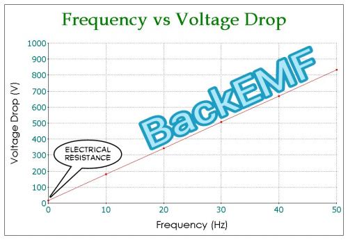
Continuing in this "basic understanding" train of thought from the last post I use FEMM to simulate a 1000 turn 22 AWG simple coil suspended in air so the flux linkage is very low.
If you begin at zero frequency there is a Voltage Drop that is simply due to the resistance of copper wire at 10 amps of DC current. That is a very low Voltage Drop relatively speaking.
As you increase the frequency the Voltage Drop that occurs suggests that the oscillation is "fighting against something" which is the creation and the destruction of this magnetic field that radiates around the coils. (resistance and eddy currents are small factors compared to the flux changes)
This is just air... so the maximum flux is less than 0.1 Tesla (green / yellow areas) and there is no real hysteresis to consider because this is an ironless scenario. Add iron and this increases the difficulty in switching back and forth but you get more flux at peak.
BackEMF rises linearly as frequency rises.
That alone might make you wonder... "why linear and not exponential?"
Anyway, you can easily recreate the BackEMF situation if you use FEMM.
Conductors, typically in the form of wires, may be used to transmit electrical energy or signals using an alternating current flowing through that conductor. The charge carriers constituting that current, usually electrons, are driven by an electric field due to the source of electrical energy. An alternating current in a conductor produces an alternating magnetic field in and around the conductor. When the intensity of current in a conductor changes, the magnetic field also changes. The change in the magnetic field, in turn, creates an electric field which opposes the change in current intensity. This opposing electric field is called “counter-electromotive force” (back EMF). The back EMF is strongest at the center of the conductor, and forces the conducting electrons to the outside of the conductor, as shown in the diagram on the right.
.
Skin depth is due to the circulating eddy currents (arising from a changing H field) cancelling the current flow in the center of a conductor and reinforcing it in the skin.
.
So upon further review if he had said:
"Those skin effect eddy currents sum to become the back EMF."
Then he would have been understood better.
That actually is correct.
Normally when we mention "eddy currents" we are discussing Silicon Steel laminations which is a big factor in electric motors. Hysteresis is the other parasitic loss.
.
This does actually make me look at why BackEMF is created in a different way in that it's something more localized than I thought. The use of Litz wire (many parallel small strands) should actually slightly reduce the BackEMF.
BackEMF is caused by "whatever flux is there" so all things contribute to it.
...so that "whatever" is more clearly understood as the skin effect in addition to other factors.
.
Browsers original question or statement could have been stated:
"Litz wire reduces BackEMF, so if I use a single thick wire (not many parallel or series strands) then the BackEMF will relatively speaking increase and somewhat balance the low turn count."
Which after reading more about his project this seems to be his goal which is a very high rpm motor (120kHz, 36 poles, 20k rpm and 720k erpm) which might be impossible to run with any existing controllers.
Okay... maybe this was all fantasyland anyway... but fun.
Skin effect is the tendency for high-frequency currents to flow on the surface of a conductor. Proximity effect is the tendency for current to flow in other undesirable patterns --- loops or concentrated distributions --- due to the presence of magnetic fields generated by nearby conductors. In transformers and inductors, proximity-effect losses typically dominate over skin-effect losses. In litz-wire windings, proximity effect may be further divided into internal proximity effect (the effect of other currents within the bundle) and external proximity effect (the effect of current in other bundles). However, the distinction is useful only as a form of bookkeeping. The actual losses in one strand of a litz bundle are simply a result of the total external field, due to the currents in all the other strands present.
.
So the concept of using Litz wire to significantly lower the BackEMF actually is less pronounced than you might hope because the proximity effect makes the bundle act like it's a single wire anyway.
There are slight improvements however.
In the solid wire example below you can see that very little activity occurs in the center compared to the Litz wire example above.
.
.
...overall this line of thought was useful in the end. (I learned something)
What you will notice is that as it animates the values of 0 Hz, 10 Hz and 100 Hz are almost identical. Below 100 Hz the skin effect is fairly constant, but since in this example I'm using a really thick solid wire (~ 1/4" thick) you can still observe significant Skin Effect even at 0 Hz.
A type of cable called litz wire (from the German Litzendraht, braided wire) is used to mitigate the skin effect for frequencies of a few kilohertz to about one megahertz. It consists of a number of insulated wire strands woven together in a carefully designed pattern, so that the overall magnetic field acts equally on all the wires and causes the total current to be distributed equally among them. With the skin effect having little effect on each of the thin strands, the bundle does not suffer the same increase in AC resistance that a solid conductor of the same cross-sectional area would due to the skin effect.
.
Generally speaking a 20 AWG wire is small enough to handle the Skin Effect of the typical maximum frequency of our electric motors.
Where things get interesting is this idea of twisting the wires so that a strand that might be near the center one moment will spiral to the outside the next.
Since this is extremely hard to do when hand winding (how do you keep track?) an interesting thought is to use pre-configured Litz wire with the correct self rotating strands so all the strands behave the same way.
This means machine wound Litz wire bundles which you would then apply as your coils.
Another thought is to switch to Aluminum wire because it has less Skin Effect.
Yet another is hollow copper wires or "tubes" that are of the thickness of the Skin Effect.
It's funny how these tangents open your eyes to different ideas.
So I'm thinking if copper coils tend to combine their magnetic flux because of the Proximity Effect and the Skin Effect basically means that whatever is in the middle of the coil bundle is useless then why even put it there?
Why not just hollow out the center?
And that was actually something that wikipedia was suggesting which is to switch to something more like a copper tube.
The results are impressive.
You can hollow out 4/5ths of the coil and for the same energy expended (different current, but same overall energy losses) you get pretty much the same activity. There is a difference, but it's slight.
Think of the weight savings.
So in those Left Side Crank Motor designs I'll be going back and doing some hollow cores. Weight reduction is always important on ebikes.
So this "Hollow Coil" concept could not only save weight, but also be used to do Water Cooling.
Just how you would construct this exactly is a little beyond me at the moment. You might build the motor in 12 segments with each part being assembled in some way.
Anyway... since all the heat comes from the current that "actually" flows through a wire (times it's length) and we know from the Proximity Effect that bundles of wires act like a solid wire (for the most part) then we also know that the Skin Effect means that as far as BackEMF is concerned the center of the flux rotation is where the maximum opposition occurs... so... (taking a breath)... we actually get most of what we want with a tube shape for our coil windings.


.
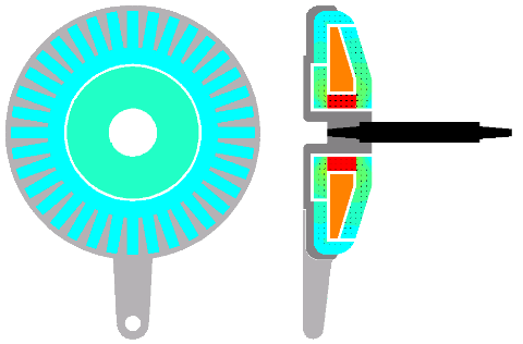
The RC motor.
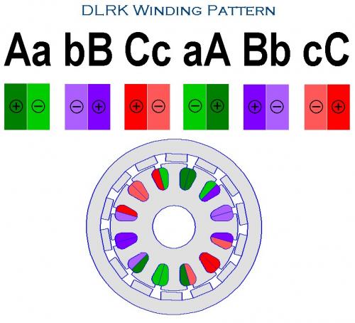
12N 14P DLRK
.
.
.
19 Phase - 19N, 20P
.

.
Resource utilization with 19 Phases reaches 95% which is a large increase over the 66% with Three Phase power.
.
Concepts for eBike Propulsion "Volume 1"
It appears the original thread has been recovered and the first post is back online. I'm going to continue with this thread as "Volume 2".
.
.
9 Phase - 18N, 20P
.
In the previous post I looked at the "extreme" of 19 Phases. That's probably beyond practical thinking, but it does show how resource utilization can be pushed as high as 95% which is a huge jump over 3 Phase with it's 66%.
9 Phases is split into opposing coils to make 18 electrical coils configured in whatever manner you choose. (the animations are more about theory)
With 9 Phases this means 8/9 of the time a coil is in use or 89% which is "good enough".
Using 20 magnets where for every magnetic flux revolution you pass two magnets means that the magnetic flux rotates 10 times faster than the magnets.
This would probably be the maximum optimization you would attempt.
And guess what?
Even pretty college girls find this interesting:
.
.
.
“Electric Machine Design” – Tutorial Lectures
Instructor: J.R. HENDERSHOT
.
Lecture 1 – History & Introduction of Electric Machine Types
http://www.motor-engineer.net/wordpress/wp-content/uploads/learn/Electric-Machine-Design_Tutorial-Lectures/Lecture1.mp4
.
Lecture 2 – Basic Electric Motor & Generator – Operational Theory
http://www.motor-engineer.net/wordpress/wp-content/uploads/learn/Electric-Machine-Design_Tutorial-Lectures/Lecture2.mp4
.
Lecture 3 – Three Phase Power Converter – Control Strategies for Three Machine Types
http://www.motor-engineer.net/wordpress/wp-content/uploads/learn/Electric-Machine-Design_Tutorial-Lectures/Lecture3.mp4
.
Lecture 4 – Practical Design Process for Electrical Machines
http://www.motor-engineer.net/wordpress/wp-content/uploads/learn/Electric-Machine-Design_Tutorial-Lectures/Lecture4.mp4
.
Lecture 5 – Electric Machine Sizing
http://www.motor-engineer.net/wordpress/wp-content/uploads/learn/Electric-Machine-Design_Tutorial-Lectures/Lecture5.mp4
.
Lecture 6 – Losses in Electrical Machines
http://www.motor-engineer.net/wordpress/wp-content/uploads/learn/Electric-Machine-Design_Tutorial-Lectures/Lecture6.mp4
.
Lecture 7 – Analytical design method vs FEA analysis method
http://www.motor-engineer.net/wordpress/wp-content/uploads/learn/Electric-Machine-Design_Tutorial-Lectures/Lecture7.mp4
.
Lecture 8 – Electric Machine Performance Discussion
http://www.motor-engineer.net/wordpress/wp-content/uploads/learn/Electric-Machine-Design_Tutorial-Lectures/Lecture8.mp4
.
Lecture 9 – Magnetic Materials for Electric Machines
http://www.motor-engineer.net/wordpress/wp-content/uploads/learn/Electric-Machine-Design_Tutorial-Lectures/Lecture9.mp4
.
Lecture 10 – Selection of Phases, Poles, Stator & Rotor Slots
http://www.motor-engineer.net/wordpress/wp-content/uploads/learn/Electric-Machine-Design_Tutorial-Lectures/Lecture10.mp4
.
Lecture 11 – Sator Configuration Design Criteria
http://www.motor-engineer.net/wordpress/wp-content/uploads/learn/Electric-Machine-Design_Tutorial-Lectures/Lecture11.mp4
.
Lecture 12 – Stator Laminations & Core Design Studies
http://www.motor-engineer.net/wordpress/wp-content/uploads/learn/Electric-Machine-Design_Tutorial-Lectures/Lecture12.mp4
.
Lecture 13 – Stator Insulation System vs. Voltage & Temperature
http://www.motor-engineer.net/wordpress/wp-content/uploads/learn/Electric-Machine-Design_Tutorial-Lectures/Lecture13.mp4
.
Lecture 14 – Stator Phase Circuits & Coil Design, Part 1
http://www.motor-engineer.net/wordpress/wp-content/uploads/learn/Electric-Machine-Design_Tutorial-Lectures/Lecture14.mp4
.
Lecture 15 – Stator Phase Circuits & Coil Design, Part 2
http://www.motor-engineer.net/wordpress/wp-content/uploads/learn/Electric-Machine-Design_Tutorial-Lectures/Lecture15.mp4
.
Lecture 16 – Introduction to Poly-Phase Induction Machines
http://www.motor-engineer.net/wordpress/wp-content/uploads/learn/Electric-Machine-Design_Tutorial-Lectures/Lecture16.mp4
.
Lecture 17 – Poly-Phase Induction Machine Theory
http://www.motor-engineer.net/wordpress/wp-content/uploads/learn/Electric-Machine-Design_Tutorial-Lectures/Lecture17.mp4
.
Lecture 18 – Poly-Phase Induction Machine Design Strategy
http://www.motor-engineer.net/wordpress/wp-content/uploads/learn/Electric-Machine-Design_Tutorial-Lectures/Lecture18.mp4
.
Lecture 19 – Equivalent Circuit Parameters, Measurements and Torque vs. Speed Plots
http://www.motor-engineer.net/wordpress/wp-content/uploads/learn/Electric-Machine-Design_Tutorial-Lectures/Lecture19.mp4
.
Lecture 20 – Rotor Design for A-Synchronous Induction Machine, Part 1
http://www.motor-engineer.net/wordpress/wp-content/uploads/learn/Electric-Machine-Design_Tutorial-Lectures/Lecture20.mp4
.
Lecture 21 – Rotor Design for A-Synchronous Induction Machine, Part 2
http://www.motor-engineer.net/wordpress/wp-content/uploads/learn/Electric-Machine-Design_Tutorial-Lectures/Lecture21.mp4
.
Lecture 22 – Performance Calculations For Inverter Fed Induction Machines
http://www.motor-engineer.net/wordpress/wp-content/uploads/learn/Electric-Machine-Design_Tutorial-Lectures/Lecture22.mp4
.
Lecture 23 – Reluctance Synchronous Motors (IM stator & Salient Pole Rotor)
http://www.motor-engineer.net/wordpress/wp-content/uploads/learn/Electric-Machine-Design_Tutorial-Lectures/Lecture23.mp4
.
Lecture 24 – Reluctance Synchronous Machine Theory
http://www.motor-engineer.net/wordpress/wp-content/uploads/learn/Electric-Machine-Design_Tutorial-Lectures/Lecture24.mp4
.
Lecture 25 – Rotor Design of Reluctance Synchronous Machines
http://www.motor-engineer.net/wordpress/wp-content/uploads/learn/Electric-Machine-Design_Tutorial-Lectures/Lecture25.mp4
.
Lecture 26 – Performance Analysis of Reluctance Synchronous Machines
http://www.motor-engineer.net/wordpress/wp-content/uploads/learn/Electric-Machine-Design_Tutorial-Lectures/Lecture26.mp4
.
Lecture 27 – PM-DC Brushless and PM-AC Synchronous Machines
http://www.motor-engineer.net/wordpress/wp-content/uploads/learn/Electric-Machine-Design_Tutorial-Lectures/Lecture27.mp4
.
Lecture 28 – PM Synchronous Design Theory, SPM & IPM Rotor Types
http://www.motor-engineer.net/wordpress/wp-content/uploads/learn/Electric-Machine-Design_Tutorial-Lectures/Lecture28.mp4
.
Lecture 29 – Permanent Magnet Rotor Design (SPM & IPM)
http://www.motor-engineer.net/wordpress/wp-content/uploads/learn/Electric-Machine-Design_Tutorial-Lectures/Lecture29.mp4
.
Lecture 30 – Performance Calculations for SPM & IPM Brushless Machines
http://www.motor-engineer.net/wordpress/wp-content/uploads/learn/Electric-Machine-Design_Tutorial-Lectures/Lecture30.mp4
.
Lecture 31 – Torque vs Speed & Kt vs. Ke, SPM, IPM & PMSM brushless motors
http://www.motor-engineer.net/wordpress/wp-content/uploads/learn/Electric-Machine-Design_Tutorial-Lectures/Lecture31.mp4
.
Lecture 32 – PM Synchronous Generator Design Principles
http://www.motor-engineer.net/wordpress/wp-content/uploads/learn/Electric-Machine-Design_Tutorial-Lectures/Lecture32.mp4
.
Lecture 33 – Thermal Design Considerations for Electric Machines
http://www.motor-engineer.net/wordpress/wp-content/uploads/learn/Electric-Machine-Design_Tutorial-Lectures/Lecture33.mp4
.
Lecture 34 – Electric Machine Cooling Strategies
http://www.motor-engineer.net/wordpress/wp-content/uploads/learn/Electric-Machine-Design_Tutorial-Lectures/Lecture34.mp4
.
Lecture 35 – Mechanical Design Issues for Electrical Machines
http://www.motor-engineer.net/wordpress/wp-content/uploads/learn/Electric-Machine-Design_Tutorial-Lectures/Lecture35.mp4
.
Lecture 36 – Manufacturing Practices of Electrical Machines
http://www.motor-engineer.net/wordpress/wp-content/uploads/learn/Electric-Machine-Design_Tutorial-Lectures/Lecture36.mp4
.
.
Normally we think of the physical shape of the motor first, then we think about how we can best adapt our understanding of copper-to-iron interactions to achieve the most efficiency we can get from the desired geometry to create the maximum magnetic flux.
So then I thought... what if we designed for efficiency first?
Well, you would want 100% of the copper to actually create flux in the iron (silicon steel) so the ideal would be to make a pancake of iron-copper-iron-copper in order to get all the current translated into flux.
The image shows what that looks like.
What is interesting is that the entire chuck of silicon steel gets activated with no more than a watt of energy and it's something like a pound of silicon steel.
Could one build a "flux capacitor" as a separate component?
Well more or less "yes" you could.
Then you start to think about compartmentalizing the function of "flux creation" and "flux usage" as two separate functions.
Sort of an Object Oriented design technique.
Makes you go hmmmmmmm.
.
.
This is a seemingly new idea... at least for me.
You combine the Cycloidal Drive concept with an electric motor.
In this case it's 6 Teeth -> 7 Teeth, so only a slight gear reduction, but if you increased those numbers to something like 20 Teeth -> 21 Teeth then you have a 20-to-1 gear reduction built into the motor itself.
Also the more you increase the base number of teeth you also reduce the difference in diameter of the gears which means there is less vibration and it also reduces the air gap variability.
Friction is only the gears themselves touching each other. You should be able to not need a bearing because the side to side movement could be controlled with another set of magnets on either side of the motor magnets. The center gear would run on bearings however.
I'll have to do another animation with higher numbers of teeth. This was just so that I made sure the math is right. (there was a slight error that was corrected half way through)
.
You would have to keep the PM "wobbler" (no longer a rotor :-) from rotating, though. I doubt the magnetic attraction would be sufficient to keep the "wobbler" from rotating once the gear is asked to drive a bike.
My rides:
2017 Zero S ZF6.5 11kW, erider Thunder 5kW
The magnet rotor wouldn't rotate much. When the coils are activated they want to center the rotor node onto a fixed location and that's actually what drives the motor shaft. Rotation is prevented... but that's actually where the torque comes from. (so it's actually the process of the rotor aligning itself that generates the torque).
Since the magnets only wiggle in a small circle (defined by the ratio of gears) when you got to something like 23 -> 24 teeth (23-to-1 gear reduction) the wiggle will be small and all you need is something to keep the magnets from side-to-side movement. The side-to-side magnetic polarity oscillates only slightly and never changes direction.
So you could place "guide magnets" on the sides of the magnets that drive the motor.
It might be like magnetic levitation... you could go with a Halbach Array, but I doubt it would be necessary. The nice thing is this aspect is frictionless.
I'll have to post some more (it's still a new idea) but in FEMM there is a natural cogging behavior so that when you turn off the wiggle power the rotor stays where you left it. The magnetic flux on the opposite side of the teeth contact area is the highest point of magnetic attraction which is good because we want the teeth to be firmly pressed together.
The issue I'm actually looking at is friction right now.
The problem with all these fractional gearing solutions is that the gear teeth approach each other at weird angles that force the teeth to generate too much friction as they slide past each other. I'm currently looking into combining the benefits of a planetary gear in the center which would "skip over" a tooth each wiggle but then alter the skew angle of the involute teeth to compensate for the advance. In the animation imagine shifting the blue line to a slight offset. If this thought process proves viable it might offer a better cycloidal drive solution which might be stand alone. (likely becoming a separate line of thought)
.
.
One other thing is that I realized you can reduce weight on the wiggle rotor with a more conventional magnet configuration (magnets pointing in and out) and if the number of magnets matches the gear teeth number you can reuse the steel in the teeth for flux transfer. Since the magnetic flux never fully reverses it should produce little heating. The back flux path doubles as the gear teeth.
How might this motor be controlled? I have no idea at this point.
Anyway... I'll keep fiddling around with it.
.
.
...that would be the Regular Planetary Gear.
.
.
...this would be the same but with one extra tooth added and a change to a Cycloidal orbiting pattern.
I'd want to play with the gear ratios and tooth angles, but the idea would be to get the high gear reduction without excessive friction due to teeth sliding against each other.
In the examples above:
Regular - 24 / 6 / 36
Cycloidal - 24 / 6 / 37
...still just thinking about the idea.
.
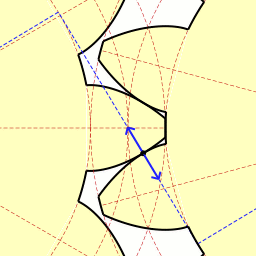
After looking at the "friction question" with the planetary gear combined with a circular cycloidal orbiting pattern it started to dawn on me that things are different than I thought.
Circular orbiting has less friction than orbiting the entire outer gear and forcing gears of different tooth counts to grind against each other.
So I went back to a simple 18 tooth - 19 tooth cycloidal:
.

.
From this I reduced my effort by just doing a couple of teeth:
.
.
What becomes apparent is the friction isn't that bad.
Circular orbiting (around a single tooth) seems better than orbiting the entire gear.
.
.
With the circular motion of the outer orbit being really tight it opens the door to a shape that might optimize contact to only a small amount of friction. This is done with watches that use Lavet Motors and need high efficiency, so it looks pretty good. If the outer gear was made of all cam followers (with needle bearings) that would be optimal.
There is also a difference between clock gearing and circular cycloidal gearing because the contact occurs on many gear teeth as the outer gear orbits. In this example 18 (inner) and 19 (outer) gear teeth alternate one at a time applying pressure to produce torque. This means each point of contact can be controlled to occur only in favorable friction situations. You can shape teeth so that once the angle gets weird it bends away.
The magic will be in finding that geometry.
.
.
From what I've been able to figure out it looks like the best angle for the teeth is roughly square.
Contact occurs along a flat curve and only deviates slightly as the teeth pass by each other. This is good news because it should make the teeth durable. By changing the shape you can actually limit contact area and the duration of contact.
Additional contact would be needed in order to center the gears in relation to each other. Having the contact resting on the inside edge seems to make sense.
So there would be two separate contact areas, one for torque and another to position the outer gear in relation to it's intended centerline offset.
In an electric motor this inner resting place would prevent the circularly orbiting set of magnets mounted on this 19 tooth outer ring from colliding with the coils on the opposite side.
The behavior here is very unusual and different than spinning cycloidal gearsets.
An important point is that all torque ends up going through just one tooth at a time. This is great for reducing friction, but means the individual tooth must be able to handle the full torque of the motor. (that might be a problem)
.
.
Okay, a whole bunch of things going on here.
First I moved the coils inside rather than being outside, so I effectively made this an Outrunner of sorts much like the RC motors.
Next I moved the magnets inside and buried them deep into the iron. It would be near impossible to damage the magnets due to overheating.
The outer ring of circles could be cams with needle bearings. This reduces friction to next to nothing and calms any worries about low efficiency based on friction.
The gears are 24 teeth inner and 25 teeth (cams) outer so the effective gear reduction is 25-to-1 or in other words it could spin at 2500 rpm and yield 100 rpm at the pedals.
The part that actually "wiggles" (in a small circle) is now made of one piece of silicon steel and has no attachments that might fall off. How to construct that for both mechanical strength and magnetic flux is a big question mark. Eddy currents are a problem if it isn't laminated.
Power would be generated through coils on the inner nodes. The rounded shape of those nodes actually increases the surface area and increases magnetic flux transfer.
Still looking into other ideas.
.
.
Cycloidal motor with 48 inner teeth and 49 outer teeth giving it a built in 49-to-1 gear reduction.
This means a 5000 rpm (equivalent) motor speed produces 100 rpm output.
Note how the inner gear doesn't rotate. It goes in little circles but doesn't actually rotate. With proper tooth shape the friction should be less than with a rotating inner gear.
Will this vibrate like crazy?
Absolutely... that's a big problem.
.
.
Okay now you are probably wondering why I'm adding porn...
Actually it's not porn, but the magnetic flux that occurs using the same frequency of oscillation (20 Hz) and current (10 A) but varying the position of the magnetically inductive element.
What happens is the Voltage Drop varies depending on the "effect" the coils have in creating the magnetic flux. Flux Linkage defines Voltage Drop.
.

.
What this means is you can "sense" where the rotor is in something like a switched reluctance motor at any time.
And with the PAS (Pedal Assist System) requirement on many new ebikes the startup problem disappears. The controller / computer only needs to send pulses of current through the system and measure the Voltage Drop to know rotor position. Very little power is used to send out these test pulses.
We know what is going on by wiggling the current and seeing how much opposition we get to doing that. More opposition (reactance) means the inductive element is centered and less means it's off center and permitting less flux.
.
Expecting more info about it...
Keep calm and whizz on.
Okay... was kind of working on another magnetic concept, but I'll look at Flux Linkage again.
.
.
So if we looked at an ordinary transformer there is 100% Flux Linkage in a simple square path. Other than hysteresis and other losses every magnetic field created in one side will be recreated on the other side. The Voltage Drop is at it's highest because the alternating current drives a load as well as alternate the magnetic flux.
.
.
If we break the Flux Linkage you will now not get any circulation in the square path and so the load will end up not being driven. The alternating current on the left will create a magnetic flux but the path is now into air which acts as a weak flux path.
So it's pretty clear that circulating magnetic flux requires work on the part of the left side coil and that work is seen in terms of the Voltage Drop.
Extending the idea to the general case you arrive at the idea of the generic BackEMF concept which can apply to any change in field.
In short anytime you create a flux it costs you a Voltage Drop because you are doing something. Even though there aren't permanent magnets in something like a Switched Reluctance motor you still have a dynamically changing Flux Linkage. Therefore, if you sent out small "test pulses" as the Flux Linkage changed with time you could measure that to know what is going on. I think the FOC ("Field Oriented Control") chips do something like this in their "learning mode". They will send out testing pulses and see what comes back and from that they can derive the abstract motor model that then is used to drive it.
One trades voltage for flux and then flux for torque.
.
.
With a small efficiency cost in these "test pulses" you could control a PAS ("Pedal Assist System") without needing any more than a Single Phase and without actually using sensors. The degree of how far you could perfect this is not clear, but the FOC chips have gotten really good these days.
.
.
Continuing in the PAS thought process...
I ran some simulations in a simple Flux Linkage situation and compared the Maximum Flux Linkage to the Minimum Flux Linkage and how variables like Current (Amps - A) and Frequency (Hz) effect the Voltage Drop.
Nothing unexpected.
It looks pretty linear so as you increase either the Current or the Frequency or both the Voltage Drop increases.
.

.
However it's likely linear because the Current is fairly low. If you pushed things harder or faster you would get effects related to the Hysteresis of the Silicon Steel being used.
The simple concept in all this is that whenever you create a Flux in the Silicon Steel it takes more effort to get back to neutral than if you never created the Flux.
PAS based ebikes could be made to operate without magnets and simply run a kind of sensorless Switched Reluctance setup which uses clever programming to sense position.
An important point is that you only get the Voltage Drop because you "wiggle" the current back and forth to cause a Hysteresis loss in the Silicon Steel. A constant current will not give you any valuable information. This is why you would do this as a "pulse", but hopefully not cost too much in terms of energy wasted.
.
When the Flux Linkage is at it's lowest the Inductance will be at it's lowest and the Delay in voltage change with time will be short:
.
.
But when the Flux Linkage is high the (apparent) Inductance is high so the Delay gets longer:
.
.
Now keep in mind how PWM (Pulse Width Modulation) actually works. One doesn't simply flood your motor with raw current, but instead you feed it "pulses" where at low throttle the pulses are few (low Duty Cycle) and at full throttle there are many "pulses" (high Duty Cycle) so this sort of thing already happens.
The trick would be to have some built in feature that would measure a very specific voltage in a tightly controlled time period. Since you could measure the entire area it could be done in some sort of capacitive side circuit that would trap the voltage rise and then report that figure rather than just the incremental voltage in some instant.
Fast rising voltage means low Inductance and less Flux Linkage.
Slow rising voltage means high Inductance and more Flux Linkage.
...in reality the Silicon Steel will behave in some non-linear ways relative to a pure inductor, but the early stages will be "mostly linear".
As the rider pedals a PAS ebike you could send out these tracer "pulses" that are as short and spread out as possible just so you can figure out what is happening. Once the controller learns what is happening it then begins to add power as is appropriate.
My "guess" is that as the rider slows down his pedal pace this will show up in the readings as being like a generator providing negative feedback. This would then signal that power would need to reduced. All this will occur at speeds hundreds of times faster than human perception.
Dave: Well, we'd be in very serious trouble.
Frank: We would, wouldn't we?
Dave: Hmm, hmm.
Frank: What the hell can we do?
Dave: Well, we wouldn't have too many alternatives.
Frank: I don't think we'd have any alternatives. There isn't a single aspect of ship operations that's not under his control. If he were proven to be malfunctioning, I wouldn't see how we would have any choice but disconnection.
Dave: I'm afraid I agree with you.
Frank: There'd be nothing else to do.
Dave: It would be a bit tricky.
Frank: Yeah.
Dave: We would have to cut his higher-brain functions...without disturbing the purely automatic and regulatory systems. And we'd have to work out the transfer procedures of continuing the mission under ground-based computer control.
Frank: Yeah. Well that's far safer than allowing HAL to continue running things.
.
.
The Hutchison Effect is really interesting.
Basically if you use electromagnetic waves inside a microwave oven you can heat water because the resonant frequency exactly matches the internal molecular structure of H2O.
All this does is take it to the next level and creates a complex set of waves that exactly matches the resonant frequency of a metal.
You can melt metal without heat using electromagnetic waves.
For those curious about the 911 Mystery this is a possible way to explain why buildings collapsed in ways that defied the ordinary laws of physics.
It seems like Stealth technology... something we aren't aware is being used. (a new weapons system possibly?)
Anyway... it's interesting because it's existence is something that relates to all the same component parts we use to create electric motors: electricity, magnetism, metal resonances and hysteresis, etc.
Practical usefulness for ebikes? Hmmmmm, not likely, but it does open your mind to thinking about these forces in a different way.
On an ebike when the motor decomposes we consider this "undesireable".
.
.
A motor based on switched reluctance alone will have three things that must be modeled in order to accurately reproduce and then control it's behavior.
Resistance - This can be learned by applying a steady constant current through the coil.
Inductance - This is the copper inductance alone and requires an alternating current or pulses at minimum to be learned.
Hysteresis - This is dependent on the shape, size and position of the rotor and stator which are made up of silicon steel laminations.
One can see the Hysteresis as a kind of "memory" because when you induce a magnetic flux in silicon steel it will leave a Remanence afterwards. This is why backEMF grows with motor speed and frequency because Hysteresis becomes more "expensive" to reverse as you do it faster.
In order to separate Inductance and Hysteresis you would have to run a variety of test frequencies to differentiate (as well as possible) what values would represent these variables. The "best fit available" would be chosen which is different than the "exact fit".
Early computer memory relied entirely on Hysteresis in silicon steel, but there are new advances in this idea of a "memristor".
.
.
This is a continuation of past Left Side Crank Motor thinking.
In this design the Toroidally wound copper coils and Silicon Steel stator are mounted so that they can be screwed directly into the Left Handed threads of a standard Bottom Bracket. There will likely need to be some type of torque bar to prevent it from coming loose as the forces seem to want to unwind it.
Another thought is to move the left Bottom Bracket bearing to a place further to the left if that might increase rigidity but that would require a longer spindle so more replacement parts.
This would be Single Phase PAS so no start up issues are involved. Sensing would be done without physical sensors as was discussed in the previous post.
It's technically a Switched Reluctance design.
This would be intended for use within the 250 Watt legal limitations, but might be capable of 750 watts, not sure at this point.
.
No cogging.
No friction caused by gears.
No breakable parts.
No front freewheel.
No conflicts with the chainrings mounted on the Right Side crank.
.
.
So I'm looking at the Left Side Crank Motor idea and wondering if different angles of interaction for the air gap would change anything.
Well... it does.
Seems that at about 30 degrees you get the maximum magnetic flux, then as you continue to increase the angle the flux goes back down again. The sharp angle tends to make the flux get bunched up where things narrow. But the completely square starting angle isn't so great because the area of interaction is smaller.
It's a rather weird result, but interesting and it suggests that the correct design can be very subtle.
.
.
This is the first product that I know of that is dedicated to the Left Side Crank Motor concept.
Once you go PAS there's no reason not to do this.
.
http://www.b-labs.org/e-ram-motor/
.
The motor is the heart and mind (quite literally) of the e-ram system. It consists of five subsystems. Each has a distinct function.
The motor electronics are the brain of the whole system. They get power from the battery, all the information from other parts of the system converge here, in turn, it supplies the current to run the electric motor.
The electric motor converts this electrical power to mechanical power. In the e-ram, we used a high torque brushless DC motor, that you would otherwise find in industrial robots similar high tech applications. Despite its small stature, it packs quite a punch.
All this is not yet enough for a bike center motor, as we are now running at over 3.000 rpm. To get this down to a more usable speed, we need to use a reduction gear. This particular type of reduction gear is called an eccentric gear with a ratio of 30. This means for every 30 rotations of the electric motor, the output turns once.
Because you need to be able to pedal freely in both directions without having to turn the motor, we need a clutch between the motor and the crank. This enables the motor to engage and power the crank arm directly, but also enables to rider to pedal purely by muscle power, without any resistance by the motor.
At last, the torque and the speed sensor are necessary to tell the electronics how hard and fast the rider is pedaling. This information is necessary to give the rider a smooth and unobtrusive riding experience.
Specs
• Weight drive unit (w/o crank): 1.45 kg
• Weight crankset ( incl. axle & chainring): 0.85 kg
• Weight battery pack: 2.4 kg
• Motor data: 250 watt - max 60 Nm torque
• Voltage: 48V
.

.
Essentially it's a motor with a high gear reduction (30-to-1) all packaged neatly on the left hand side.
Very nice.
.
.
What is also interesting is that they tried something like a John Vranish style compound gear reduction and it was "too noisy" which seems to agree with the other things I've read that suggests when teeth are out of phase with each other it places a lot of friction on the teeth and that will create heat and noise. So it seems the eccentric designs are better despite the fact they vibrate. Better to have vibration than heat and metal noise.
.
.
They have also apparently improved on the shape of the teeth in the eccentric versions which I have noticed is important based on what I've been playing around with. These guys seem to know their stuff.
This is their seventh iteration, but first real "ready for primetime" product yet it is unclear who will actually build it because other players are getting involved:
.
We would like to announce that we hereby abort this (kickstarter) campaign!
We do this with mixed feelings although the reasons for this step are of positive nature. However this decision also leaves some tears in our eyes as we humans not easily give away our “babies”.
During the period of this project we have been partnering with a company called Joy Industrial Ltd., which is running the famous wheel brand “Novatec Wheels”. As the e-ram Project turned out to become very promising, ongoing negotiations with our partner turned into a different direction as originally planned. However due to the positive feedback from inside of the industry as well as through this campaign, our partner decided to put more resources into the project and take over the project ownership to reach out for stronger goals. This implies a different path towards industrialization, which means that it would not be possible to guarantee delivery dates, no matter if the campaign would have been successfully finished or not.
Because of this pending situation we did not actively push the campaign in the past 14 days and now take action to abort the campaign and inform you.
You can see the E-ram engine at the Novatec Wheels Eurobike booth this week. We as the creators of e-ram wish Novatec all the best and eagerly await e-ram become true during the year 2016. Stay tuned, the BIONICON edison EVO´s are ready for e-ram
Your BIONICON and B-Labs team
.
So this might actually be bigger than the inventors can handle and production might be moved elsewhere. (China)
I wonder how much they sold out for?
$100k?
$200k?
More?
http://www.joy-tech.com.tw
.
.
Fast forward to 6:15.
It's good to keep up on all the latest developments in ebikes and Interbike is definitely the "mecca" for doing that these days.
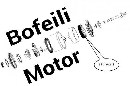
The Surface 604 is just 33 lbs and has a PAS mid-drive motor with 350 watts of power and if I listened correctly it's a Bofeili motor:
.
.
...looks pretty simple, just a single planetary gear, but that might be enough when you are dealing with European standards of power.
My thanks to ElectricBikeReview for the use of the video.
.
.
https://endless-sphere.com/forums/viewtopic.php?f=30&t=75622&start=25
It's fun to look back to people struggling with the fundamentals and having misunderstandings.
I remember when I was rewiring motors with different copper winding configurations and it dawned on me that if you paralleled the copper wires you would increase current flow (which it does) but due to the fact my old brushed motor lost power beyond about 6,000 rpm I wasn't seeing the upper limits of the increased Kv and my controller wasn't capable of providing the amps I wanted and the batteries sagged a lot anyway so it took some time to figure out what was really happening.
What this guy seems to be confused about is that he thinks BackEMF is caused by Eddy Currents.
No.
BackEMF is the combined reaction to the entire magnetic field that the Amp-Turns in the copper creates through the motor. The full magnetic field involves the flux linkage which changes as the motor rotates.
It's an error that I see as easy to make... it's an over simplification.
.
.
This was from a few posts back where I looked at how the flux linkage in a Switched Reluctance motor would show a differing Voltage Drop depending on the rotor position and you could use this information to create a sensorless control system.
BackEMF is the universe pushing back against the useful work you are creating inside your motor.
.
The best way to think about this stuff is that you want to have maximum copper fill to achieve maximum efficiency.
Then you decide how your Amp-Turns will create a Kv that suits the needs you have as far as motor rpm. You want to match your Kv to your battery voltage so that they all work well with your system.
It is possible to do a very low voltage battery and high Kv motor combination, but the problem is that controller efficiency is not very good below about 20 volts so it's better to make your system around that as a minimum. The best MOSFETS operate much higher at 100 volts.
.
Update: Looks like they still haven't figured it out yet on the endless-sphere thread. Luke ("Deathbike") used to be the brains over there but he seems to have lost interest in these novice rants.
BackEMF occurs either by motion of a magnetic field relative to a fixed coil or by changing magnetic fields that are stationary. Why? Because all magnetic fields have a circular flux rotation and because of trigonometry as things move into different relative positions the influence of the flux vector changes.
BackEMF is caused by "whatever flux is there" so all things contribute to it.
What makes electric motor design interesting is how all these many factors need to be understood and then combined to achieve the optimal compromise which achieves the highest efficiencies.
The most efficient idea so far is the CSIRO style solar racer motor with Halbach Arrays on either side in an Axial Flux design with nothing but copper coils to drive the motor. There is no iron at all. There are heat issues with this design however.
Even in this CSIRO design there is still BackEMF because having to change any oscillating field requires the existing field to collapse and you are in effect "forcing" the field to collapse. Nature demands that everything balances, so any change in a stable state "costs" something in terms of energy. This might simply be the presence or absence of a current so in the "ideal" resistance free utopia (zero degrees kelvin superconductor) it's possible to make this trade without losses, but usually we pay with electrical resistance.
Electricity and magnetism are simply two "faces" of the same energy.
.
.
Continuing in this "basic understanding" train of thought from the last post I use FEMM to simulate a 1000 turn 22 AWG simple coil suspended in air so the flux linkage is very low.
If you begin at zero frequency there is a Voltage Drop that is simply due to the resistance of copper wire at 10 amps of DC current. That is a very low Voltage Drop relatively speaking.
As you increase the frequency the Voltage Drop that occurs suggests that the oscillation is "fighting against something" which is the creation and the destruction of this magnetic field that radiates around the coils. (resistance and eddy currents are small factors compared to the flux changes)
This is just air... so the maximum flux is less than 0.1 Tesla (green / yellow areas) and there is no real hysteresis to consider because this is an ironless scenario. Add iron and this increases the difficulty in switching back and forth but you get more flux at peak.
BackEMF rises linearly as frequency rises.
That alone might make you wonder... "why linear and not exponential?"
Anyway, you can easily recreate the BackEMF situation if you use FEMM.
.
.
.
https://en.wikipedia.org/wiki/Skin_effect
.
Conductors, typically in the form of wires, may be used to transmit electrical energy or signals using an alternating current flowing through that conductor. The charge carriers constituting that current, usually electrons, are driven by an electric field due to the source of electrical energy. An alternating current in a conductor produces an alternating magnetic field in and around the conductor. When the intensity of current in a conductor changes, the magnetic field also changes. The change in the magnetic field, in turn, creates an electric field which opposes the change in current intensity. This opposing electric field is called “counter-electromotive force” (back EMF). The back EMF is strongest at the center of the conductor, and forces the conducting electrons to the outside of the conductor, as shown in the diagram on the right.
.
Skin depth is due to the circulating eddy currents (arising from a changing H field) cancelling the current flow in the center of a conductor and reinforcing it in the skin.
.
So upon further review if he had said:
Then he would have been understood better.
That actually is correct.
Normally when we mention "eddy currents" we are discussing Silicon Steel laminations which is a big factor in electric motors. Hysteresis is the other parasitic loss.
.
This does actually make me look at why BackEMF is created in a different way in that it's something more localized than I thought. The use of Litz wire (many parallel small strands) should actually slightly reduce the BackEMF.
...so that "whatever" is more clearly understood as the skin effect in addition to other factors.
.
Browsers original question or statement could have been stated:
"Litz wire reduces BackEMF, so if I use a single thick wire (not many parallel or series strands) then the BackEMF will relatively speaking increase and somewhat balance the low turn count."
Which after reading more about his project this seems to be his goal which is a very high rpm motor (120kHz, 36 poles, 20k rpm and 720k erpm) which might be impossible to run with any existing controllers.
Okay... maybe this was all fantasyland anyway... but fun.
.
.
Proximity Effect
http://www.dartmouth.edu/~sullivan/litzwire/skin.html
.
Skin effect is the tendency for high-frequency currents to flow on the surface of a conductor. Proximity effect is the tendency for current to flow in other undesirable patterns --- loops or concentrated distributions --- due to the presence of magnetic fields generated by nearby conductors. In transformers and inductors, proximity-effect losses typically dominate over skin-effect losses. In litz-wire windings, proximity effect may be further divided into internal proximity effect (the effect of other currents within the bundle) and external proximity effect (the effect of current in other bundles). However, the distinction is useful only as a form of bookkeeping. The actual losses in one strand of a litz bundle are simply a result of the total external field, due to the currents in all the other strands present.
.
So the concept of using Litz wire to significantly lower the BackEMF actually is less pronounced than you might hope because the proximity effect makes the bundle act like it's a single wire anyway.
There are slight improvements however.
In the solid wire example below you can see that very little activity occurs in the center compared to the Litz wire example above.
.
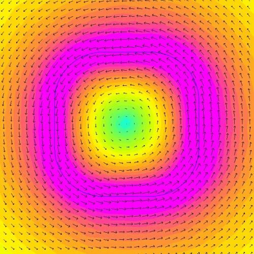
.
...overall this line of thought was useful in the end. (I learned something)
.
.
The Skin Effect Animation has the following frequencies:
0 Hz, 10 Hz, 100 Hz, 1000 Hz, 10,000 Hz, 100,000 Hz, 1,000,000 Hz
What you will notice is that as it animates the values of 0 Hz, 10 Hz and 100 Hz are almost identical. Below 100 Hz the skin effect is fairly constant, but since in this example I'm using a really thick solid wire (~ 1/4" thick) you can still observe significant Skin Effect even at 0 Hz.
.
https://en.wikipedia.org/wiki/Skin_effect
.
A type of cable called litz wire (from the German Litzendraht, braided wire) is used to mitigate the skin effect for frequencies of a few kilohertz to about one megahertz. It consists of a number of insulated wire strands woven together in a carefully designed pattern, so that the overall magnetic field acts equally on all the wires and causes the total current to be distributed equally among them. With the skin effect having little effect on each of the thin strands, the bundle does not suffer the same increase in AC resistance that a solid conductor of the same cross-sectional area would due to the skin effect.
.
Generally speaking a 20 AWG wire is small enough to handle the Skin Effect of the typical maximum frequency of our electric motors.
Where things get interesting is this idea of twisting the wires so that a strand that might be near the center one moment will spiral to the outside the next.
Since this is extremely hard to do when hand winding (how do you keep track?) an interesting thought is to use pre-configured Litz wire with the correct self rotating strands so all the strands behave the same way.
This means machine wound Litz wire bundles which you would then apply as your coils.
Another thought is to switch to Aluminum wire because it has less Skin Effect.
Yet another is hollow copper wires or "tubes" that are of the thickness of the Skin Effect.
.
.
It's funny how these tangents open your eyes to different ideas.
So I'm thinking if copper coils tend to combine their magnetic flux because of the Proximity Effect and the Skin Effect basically means that whatever is in the middle of the coil bundle is useless then why even put it there?
Why not just hollow out the center?
And that was actually something that wikipedia was suggesting which is to switch to something more like a copper tube.
The results are impressive.
You can hollow out 4/5ths of the coil and for the same energy expended (different current, but same overall energy losses) you get pretty much the same activity. There is a difference, but it's slight.
Think of the weight savings.
So in those Left Side Crank Motor designs I'll be going back and doing some hollow cores. Weight reduction is always important on ebikes.
.
.
So this "Hollow Coil" concept could not only save weight, but also be used to do Water Cooling.
Just how you would construct this exactly is a little beyond me at the moment. You might build the motor in 12 segments with each part being assembled in some way.
Anyway... since all the heat comes from the current that "actually" flows through a wire (times it's length) and we know from the Proximity Effect that bundles of wires act like a solid wire (for the most part) then we also know that the Skin Effect means that as far as BackEMF is concerned the center of the flux rotation is where the maximum opposition occurs... so... (taking a breath)... we actually get most of what we want with a tube shape for our coil windings.
What to do with that tube?
Water Cooling.
.
Pages